Big Joe PTE 30 Series Use and care manual

Big Joe Manufacturing Company • Des Plaines, IL 60018 MANUAL NO. 901467
06/20/2017
PTE 30 SERIES
SELF-PROPELLED, PALLET
LIFT TRUCK
Operation
Maintenance
Repair Parts List

WARNING
Do not operate this truck unless you have been autho-
rized and trained to do so, and have read all warnings
and instructions in Operator’s Manual and on this
truck.
Do not operate this truck until you have checked its
condition. Give special attention to tires, horn, battery,
controller, lift system, brakes, steering mechanism,
guards and safety devices.
Operate truck only from designated operating position.
Do not carry passengers. Keep feet clear of truck and
wear foot protection.
Observe applicable traffic regulations. Yield right of
way to pedestrians. Slow down and sound horn at
cross aisles and wherever vision is obstructed.
Start, stop, travel, steer and brake smoothly. Slow
down for turns and on uneven or slippery surfaces that
could cause truck to slide or overturn. Use special
care when traveling without load as the risk of overturn
may be greater.
Always look in direction of travel. Keep a clear view,
and when load interferes with visibility, travel with load
trailing.
Use special care when operating on ramps travel
slowly, and do not angle or turn. Travel with lifting
mechanism downhill.
Do not handle loads which are higher than the load
backrest or load backrest extension unless load is
secured so that no part of it could fall backward.
Before lifting, be sure load is centered, forks are com-
pletely under load, and load is as far back as possible
against load backrest.
When leaving truck, neutralize travel control, fully
lower lifting mechanism and set brake. When leaving
truck unattended, also shut off power.

901467 i
TABLE OF CONTENTS
Section Page Section Page
1 DESCRIPTION............................................................1-1
1-1. INTRODUCTION..............................................1-1
1-2. GENERAL DESCRIPTION...............................1-1
1-3. SAFETY FEATURES. ......................................1-2
2 OPERATION ...............................................................2-1
2-1. GENERAL. .......................................................2-1
2-2. OPERATING PRECAUTIONS. ........................2-1
2-3. BEFORE OPERATION.....................................2-1
2-4. GENERAL CONTROL OPERATION................2-4
2-5. DRIVING AND STOPPING PROCEDURES....2-4
2-6. BELLY-BUTTON SWITCH...............................2-4
2-7. STEERING ARM PNEUMATIC SPRING.........2-5
2-8. LIFT AND LOWER CONTROLS. .....................2-5
2-9. LOADING AND UNLOADING. .........................2-5
2-10. PARKING. ........................................................2-5
3 PLANNED MAINTENANCE ........................................3-1
3-1. GENERAL. .......................................................3-1
3-2. MONTHLY AND QUARTERLY CHECKS........3-1
3-3. BATTERY CARE.............................................3-1
3-4. CHARGING BATTERIES.................................3-1
3-5. LUBRICATION. ................................................3-2
4 TROUBLESHOOTING ................................................4-1
4-1. GENERAL ........................................................4-1
4-2. TRANSISTOR CONTROLLER
TROUBLESHOOTING .....................................4-4
4-2.1. FAULT DETECTION. .......................................4-4
4-2.2. HAND HELD PROGRAMMER (OPTIONAL)....4-5
4-2.3. FAULT RECORDING.......................................4-5
4-2.4. FAULT RECOVERY.........................................4-5
4-2.5. GENERAL CHECKOUT...................................4-5
4-2.6. ADJUSTMENT .................................................4-6
4-2.7. DIAGNOSTICS AND TROUBLESHOOTING...4-7
4-2.8. PROGRAMMER DIAGNOSTICS.....................4-7
5 STEERING ARM AND CONTROL HEAD SERIVCE ..5-1
5-1. CONTROL HEAD.............................................5-1
5-1.1. CONTROL HEAD REMOVAL. .........................5-1
5-1.2. BELLY-BUTTON SWITCH REPLACEMENT...5-1
5-1.3. LIFT, LOWER AND HORN SWITCH
REPLACEMENT...............................................5-1
5-1.4. DIRECTIONAL SWITCH REMOVAL AND
ADJUSTMENT. ................................................5-1
5-1.5. POTENTIOMETER REMOVAL TESTING
AND ADJUSTMENT.........................................5-4
5-1.6. CONTROL HEAD INSTALLATION. .................5-5
5-2. STEERING ARM..............................................5-5
5-2.1. PNEUMATIC SPRING REPLACEMENT..........5-5
5-2.2. STEERING ARM REMOVAL............................5-5
5-2.3. STEERING ARM INSTALLATION....................5-5
6 BRAKE SERVICING................................................... 6-1
6-1. BRAKES. ......................................................... 6-1
6-1.1. BRAKE REMOVAL.......................................... 6-1
6-1.2. BRAKE INSTALLATION.................................. 6-1
7 TRANSMISSION, DRIVE WHEEL, LOAD
WHEEL, BALANCE WHEEL AND ENTRY
ROLLER SERVICING................................................. 7-1
7-1. DRIVE WHEEL................................................ 7-1
7-2. DRIVE ASSEMBLY ......................................... 7-1
7-2.1. REMOVAL. ...................................................... 7-1
7-2.2. REPAIR ........................................................... 7-1
7-2.3. INSTALLATION. .............................................. 7-1
7-3. LOAD WHEEL. ................................................ 7-1
7-3.1. REMOVAL ....................................................... 7-1
7-3.2. REPAIR .......................................................... 7-4
7-3.3. LOAD WHEEL INSTALLATION....................... 7-4
7-4. CASTERS........................................................ 7-5
7-4.1. REMOVAL ....................................................... 7-5
7-4.2. REPAIR ........................................................... 7-5
7-4.3. INSTALLATION ............................................... 7-5
7-5. ENTRY ROLLERS........................................... 7-6
7-5.1. ENTRY ROLLER REMOVAL........................... 7-6
7-5.2. ENTRY ROLLER REMOVAL........................... 7-6
8 ELEVATION SYSTEM SERVICING........................... 8-1
8-1. GENERAL........................................................ 8-1
8-2. LIFT LINKAGE................................................. 8-1
8-2.1. REMOVAL ....................................................... 8-1
8-2.2. REASSEMBLY ................................................ 8-1
8-3. POWER SECTION AND FORK SECTION...... 8-1
8-3.1. SEPARATING POWER SECTION AND
FORK SECTION.............................................. 8-1
8-3.2. FORK FRAME REPAIR................................... 8-1
8-3.3. FRAME REPAIR.............................................. 8-1
8-3.4. MATING POWER SECTION AND FORK
SECTION......................................................... 8-1
9 HYDRAULIC SYSTEM SERVICING........................... 9-1
9-1. LINES AND FITTINGS .................................... 9-1
9-2. HYDRAULIC PUMP, MOTOR, AND
RESERVOIR ASSY......................................... 9-3
9-2.1. REMOVAL ....................................................... 9-3
9-2.2. DISASSEMBLY AND REASSEMBLY ............. 9-3
9-2.3. INSTALLATION ............................................... 9-3
9-2.4. LIFT CYLINDER .............................................. 9-4
9-2.5. HYDRAULIC PRESSURE ADJUSTMENT...... 9-5
10 ELECTRICAL COMPONENTS................................. 10-1
10-1. KEY SWITCH REPLACEMENT..................... 10-1
10-2. BATTERY INDICATOR REPLACEMENT...... 10-2

ii 901467
TABLE OF CONTENTS - Continued
Section Page Section Page
10-3. EMERGENCY DISCONNECT SWITCH
REPLACEMENT............................................ 10-2
10-4. DEADMAN SWITCH......................................10-2
10-4.1.REPLACEMENT............................................ 10-2
10-4.2.ADJUSTMENT............................................... 10-4
10-5. BATTERY DISCONNECT SWITCH. ............. 10-4
10-6. LIFT LIMIT SWITCH......................................10-4
10-7. ELECTRICAL CONTROL PANEL .................10-4
10-7.1.MAINTENANCE............................................. 10-4
10-7.2.CLEANING .................................................... 10-4
10-7.3.DIAGNOSTIC HISTORY................................ 10-6
10-7.4.TEST THE FAULT DETECTION CIRCUITRY10-6
10-7.5.PANEL REMOVAL.........................................10-6
10-7.6.PANEL DISASSEMBLY.................................10-6
10-7.7.PANEL INSTALLATION.................................10-7
10-8. PUMP MOTOR...............................................10-8
10-9. DRIVE MOTOR..............................................10-8
11 OPTIONAL EQUIPMENT..........................................11-1
12 ILLUSTRATED PARTS BREAKDOWN ....................12-1
LIST OF FIGURES
Figure Page Figure Page
1-1 NAME PLATE...................................................... 1-1
1-2 PTE 45 LIFT TRUCK........................................... 1-1
2-1 SAMPLE OF OPERATOR CHECK LIST............. 2-3
2-2 FORWARD/REVERSE CONTROL ..................... 2-4
2-3 PUSHBUTTON SWITCHES................................ 2-4
2-4 BRAKE ACTUATION........................................... 2-4
2-5 BELLY-BUTTON SWITCH .................................. 2-5
3-1 LUBRICATION DIAGRAM................................... 3-3
4-1 STATUS LED....................................................... 4-4
4-2 ELECTRICAL PANEL PARTS............................. 4-4
4-3 CONTROLLER TERMINALS............................... 4-5
4-4 HAND HELD PROGRAMMER ............................ 4-6
4-5 WIRING DIAGRAM (SHEET 1) ......................... 4-12
5-1 CONTROL HEAD SWITCHES ............................ 5-2
5-2 CONTROL HEAD AND STEERING ARM........... 5-3
5-3 DRIVE CONTROLS............................................. 5-4
5-4 STEERING CONTROL........................................ 5-6
6-1 TRANSMISSION, BRAKE AND DRIVE
MOTOR ASSEMBLY........................................... 6-1
7-1 DRIVE ASSEMBLY ............................................. 7-2
7-2 FORK SECTION.................................................. 7-3
7-3 WHEEL ASSEMBLY............................................ 7-4
7-4 FRAME................................................................ 7-5
8-1 FORK SECTION.................................................. 8-2
8-2 FRAME................................................................ 8-3
9-1 COMPARTMENT................................................. 9-1
9-2 HYDRAULIC SYSTEM......................................... 9-2
10-1 COMPARTMENT............................................... 10-1
10-2 STEERING CONTROL ...................................... 10-3
10-3 BRAKE ACTUATION......................................... 10-4
10-4 FRAME............................................................... 10-5
10-5 ELECTRICAL PANEL........................................ 10-7
12-1 STEERING CONTROL ...................................... 12-2
12-2 STEERING ARM................................................ 12-4
12-3 CONTROL HEAD............................................... 12-6
12-4 CONTROL HEAD............................................... 12-7
12-5 DRIVE ASSEMBLY............................................ 12-8
12-6 TRANSMISSION, BRAKE AND DRIVE
MOTOR ASSY................................................... 12-9
12-7 COMPARTMENT............................................. 12-10
12-8 DECALS........................................................... 12-12
12-9 FRAME............................................................. 12-14
12-10 FORK SECTION.............................................. 12-16
12-11 CASTER ASSEMBLY...................................... 12-18
12-12 LOAD WHEEL ASSEMBLY............................. 12-20
12-13 ELECTRICAL PANEL...................................... 12-21
12-14 HYDRAULIC SYSTEM..................................... 12-22
12-15 PUMP, MOTOR & RESERVOIR ASSEMBLY . 12-24
12-16 CYLINDER ASSEMBLY................................... 12-26
12-17 VALVE ASSEMBLY......................................... 12-28
LIST OF TABLES
Table Page Table Page
2-1 OPERATOR CHECKS.......................................... 2-2
3-1 MONTHLY AND QUARTERLY INSPECTION
AND SERVICE CHART........................................ 3-1
3-2 RECOMMENDED LUBRICANTS......................... 3-2
3-3 LUBRICATION CHART ........................................ 3-3
4-1 TROUBLESHOOTING CHART.............................4-1
4-2 ADJUSTMENT SETTINGS...................................4-7
4-3 LED CODES .........................................................4-8
4-4 TROUBLESHOOTING CHART.............................4-9

901467 1-1
SECTION 1
DESCRIPTION
1-1. INTRODUCTION.
This publication describes the 24 volt transistor
PTE 30 lift truck distributed by Big Joe Manufacturing
Company, Des Plaines, Illinois, 60018. Included are
operating instructions, planned maintenance instruc-
tions, lubrication procedures, corrective maintenance
procedures and a complete parts list with part location
illustrations.
Users shall comply with all requirements indicated in
applicable OSHA standards and current edition of
A.N.S.I. B56.1 Part II. By following these requirements
and the recommendations contained in this manual,
you will receive many years of dependable service
from your Big Joe lift truck.
1-2. GENERAL DESCRIPTION.
The self-propelled PTE 30 truck, Figure 1-2, lifts and
transports payloads up to 3000 pounds on rigid forks.
The forward and reverse motion is controlled by either
of two controller levers mounted on the control head.
Stopping and turning is controlled by the steering arm.
Lift and Lower is controlled by pushbuttons on the con-
trol head. The battery powered lift truck is quite and
without exhaust fumes.
The reversible DC motor propels the lift truck in for-
ward or reverse direction throughout the available
speed range. The PTE 30 lift truck can be driven with
forks raised of lowered. The lift truck must be pro-
tected from the elements.
The model number will be found on the name plate
(Figure 1-1) along with the serial number, lifting capac-
ity, and load center. Figure 1-2 shows the locations of
the truck’s main components and controls.
Figure 1-1 Name Plate
Figure 1-2. PTE 45 Lift Truck
R6209
R6525

1-2 901467
1-3. SAFETY FEATURES.
The PTE 30 is designed and engineered to provide
maximum safety for operator and payload. Some of
the safety features incorporated into the design are:
• Dead-man brake to apply the brake and cut off drive
power when the steering arm is released.
• Belly-button switch to reverse truck should the oper-
ator accidentally pin himself against a wall or
obstruction when backing up in slow speed.
• All control functions automatically return to “OFF”
when released.
• Externally accessible emergency disconnect switch
within operator's reach.
• Separately fused control circuits and power circuits.
• Readily accessible HORN button.
• Slip-resistance hand to provide a firm hand hold for
operator.
• Flow control valve regulates maximum lowering
speed within prescribed limits.
• Relief valve maintains hydraulic pressure within pre-
scribed limits.
• High visibility color scheme of truck provides visual
alert of truck’s presence.
• Battery Indicator
•Casters

901467 2-1
SECTION 2
OPERATION
2-1. GENERAL.
This section gives detailed operating instructions for
the PTE 30 lift truck. The instructions are divided into
the various phases of operations, such as operating
lift, driving, and stopping. Routine precautions are
included for safe operation.
2-2. OPERATING PRECAUTIONS.
WARNING: Improper operation of the lift truck may
result in operator injury, or load and/or lift
truck damage. Observe the following
precautions when operating the PTE 30
lift truck.
The following safety precautions must be adhered to
at all times.
• Do not operate this truck unless you have been
trained and authorized to do so and have read all
warnings and instructions in this manual and on the
truck.
• All warnings and instructions must be read and
understood before using the equipment.
• Equipment must be inspected by a qualified person
on a regular basis.
• Do not operate this truck until you have checked its
condition. Give special attention to Tires, Horn, Bat-
teries, Controller, Lift System, Brakes, Steering
Mechanism, Guards and Safety Devices
• Operate truck only from designated operation posi-
tion. Wear foot protection. Do not carry passengers.
• Observe applicable traffic regulations. Yield right of
way to pedestrians. Slow down and sound horn at
cross aisles and wherever vision is obstructed.
• Start, stop, travel, steer and brake smoothly. Slow
down for turns and on uneven or slippery surfaces
that could cause truck to slide or overturn. Use spe-
cial care when traveling without load as the risk of
overturn may be greater.
• Always look in direction of travel. Keep a clear view,
and when load interferes with visibility, travel with
load or lifting mechanism trailing.
• Do not overload truck. Check nameplate for load
weight and load center information.
• Before lifting, be sure load is centered, forks are
completely under load, and load is as far back as
possible against load backrest.
• Do not handle loads which are higher than the load
backrest unless load is secured so that no part of it
could fall backward.
• When leaving truck, neutralize travel control. Fully
lower lifting mechanism and set brake. When leaving
truck unattended, turn off key switch and push in the
emergency disconnect switch and remove key.
2-3. BEFORE OPERATION
Table 2-1 covers important inspection points on the
PTE 30 lift truck which should be checked prior to
operation. Depending on use, some trucks may
require additional checks.
Figure 2-1 shows a sample format for a Operator
Checklist, which can be modified as necessary to fit
your operation.
WARNING: Periodic maintenance of this truck by a
QUALIFIED TECHNICIAN is required.
CAUTION: A QUALIFIED SERVICE TECHNICIAN
should check the truck monthly for
proper lubrication, proper fluid levels,
brake maintenance, motor maintenance
and other areas specified in the SEC-
TION 3.
WARNING: If the truck is found to be unsafe and in
need of repair, or contributes to an
unsafe condition, report it immediately to
the designated authority. Do not operate
it until it has been restored to a safe
operating condition. Do not make any
unauthorized repairs or adjustments. All
service must be performed by a qualified
maintenance technician.

2-2 901467
Table 2-1 Operator Checks
ITEM PROCEDURE
Transmissionand
hydraulic sys-
tems.
Check for signs of fluid leakage.
Forks Check for cracks and damage.
Guards and load
backrest Check that safety guards are in
place, properly secured and not
damaged.
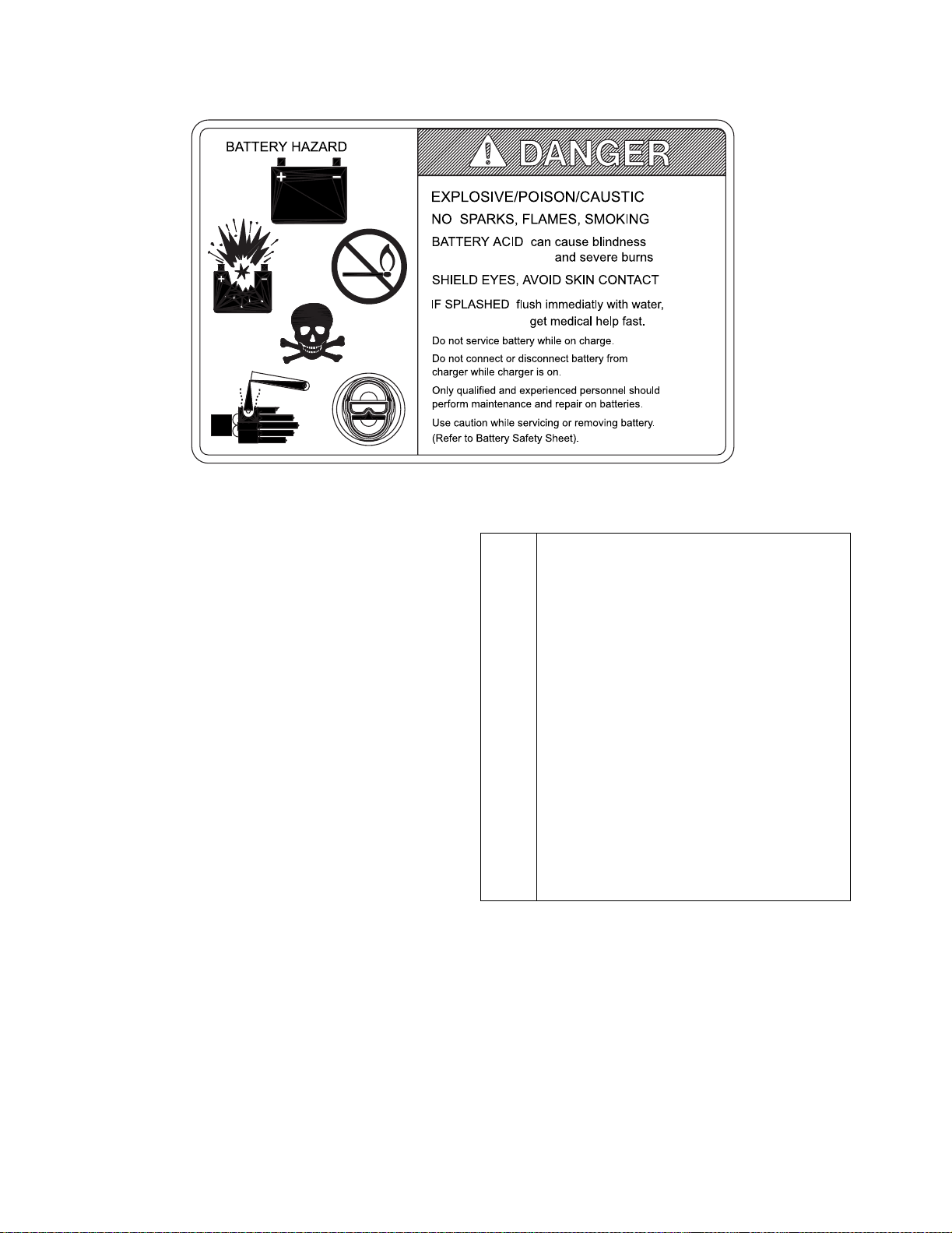
Safety signs Check that warning labels,
nameplate, etc., are in good
condition and legible.
Horn Check that horn sounds when
operated.
Steering Check for binding or looseness in
steering arm when steering.
Travel controls Check that speed controls on
control head operate in all
speed ranges in forward and
reverse and that belly button
switch functions.
Wheels Check drive wheel for cracks or
damage. Move truck to check
load for freedom of rotation.
Hydraulic
controls Check operation of lift and lower
to their maximum positions.
Brakes Check that brakes actuate when
steering arm is raised to upright
position, and when lowered to
horizontal position.
Deadman/
Parking brake Check that steering arm raises to
upright position when released
and brake applies.
Emergency
disconnect Check that emergency discon-
nect switch can be depressed
and turns off power to the truck.
Battery charge Check that battery indicator is on
“1”.
ITEM PROCEDURE

901467 2-3
Figure 2-1 Sample of Operator Check List
R6479
Electric Truck
Daily Operator Check-Off List
Date
Big Joe Manufacturing Company
Operator
Truck No. Model No.
Dept.
Check
Tires
Load Wheels
Horn
Lift Lower Control
Need MaintenanceO.K. ( )
Shift
Hour Meter
Reading Drive Hoist
Attachment Operation
Forward & Reverse Controls
Steering
Brakes
Hydraulic Leaks, Cylinders,
Valves, Hoses, Etc.

2-4 901467
2-4. GENERAL CONTROL OPERATION.
The speed control (See Figure 2-2) located on each
side of the control head provides fingertip control for
driving the truck. Rotate the control in the direction you
want to travel. The farther you rotate the control from
the neutral position, the faster the truck will travel.
Figure 2-2. Forward/Reverse Control
The pushbutton switches (See Figure 2-3), located on
the front of the control head activate the lift-lower con-
trols and the horn.
Figure 2-3. Pushbutton Switches
The brake is fully applied by lowering or raising the
steering arm. (See Figure 2-4) All traction control
power is shut off when the brake is engaged. When
the steering arm is in the upright position, the brake
acts as a parking brake. Deadman braking occurs
when the handle is released and spring action raises
steering arm to the upright position.
Figure 2-4. Brake Actuation
2-5. DRIVING AND STOPPING PROCEDURES.
1. Turn on the key switch and pull the emergency
disconnect switch out. Grasp the grips of the
steering head so that the speed control can be
comfortably operated by either thumb.
2. Lower the steering arm to a comfortable position
above horizontal to disengage the brake and to
energize the electrical circuits. See Figure 2-4.
3. To move forward (with load in front), slowly press
the speed control forward. See Figure 2-2. Press
the forward speed control farther to increase
speed.
4. To slow down or stop, release the speed control
and lower or raise the steering arm to the horizon-
tal or vertical position. See Figure 2-4. In those
positions, the brake engages, slowing or stopping
the truck.
5. Procedures for movement in reverse are the
same as in the forward direction except slowly
press the speed control backward. See
Figure 2-2.
2-6. BELLY-BUTTON SWITCH.
The belly-button switch (Figure 2-5) minimizes the
possibility of the driver being pinned by the steering
arm while driving the lift truck in slow speed. If the
switch presses against the operator while the lift truck
is being driven toward the operator, the switch
changes the direction of the lift truck.
R6453
R6452
R6526

901467 2-5
Figure 2-5. Belly-Button Switch
2-7. STEERING ARM PNEUMATIC SPRING.
The steering arm pneumatic spring automatically
raises the steering arm to the upright position when
the steering arm is released. If the steering arm does
not return fully, the steering arm pneumatic spring
requires replacement. Return truck to maintenance for
repair.
2-8. LIFT AND LOWER CONTROLS.
Lift/Lower Control buttons are located on the steering
control head. (Figure 2-3)
To lift forks, push in LIFT button and hold until forks
reach desired height. To lower forks, push in LOWER
button and hold until forks descend to desired height.
2-9. LOADING AND UNLOADING.
1. Move truck to location where load is to be picked
up.
2. Move the truck into position so forks are within
pallet or skid, and the load is centered over the
forks and as far back as possible.
3. Raise forks to lift load.
4. Drive to area where load is to be placed.
5. Move truck to align load with its new position.
6. Lower the load until it rests squarely in place and
the forks are free.
7. Slowly move the truck out from under the load.
2-10.PARKING.
When finished with moving loads, drive truck to its
maintenance or storage area. Push the emergency
disconnect switch in and turn off the key switch.
Charge batteries as necessary. Refer to battery care
instructions, SECTION 3.
R6455

2-6 901467
NOTES

901467 3-1
SECTION 3
PLANNED MAINTENANCE
3-1. GENERAL.
Planned maintenance consists of periodic visual and
operational checks, parts inspection, lubrication, and
scheduled maintenance designed to prevent or dis-
cover malfunctions and defective parts. The operator
performs the checks in SECTION 2, and refers any
required servicing to a qualified maintenance techni-
cian who performs the scheduled maintenance and
any required servicing.
3-2. MONTHLY AND QUARTERLY CHECKS.
Table 3-1 is a monthly and quarterly inspection and
service chart based on normal usage of equipment
eight hours per day, five days per week. If the lift truck
is used in excess of forty hours per week, the fre-
quency of inspection and service should be increased
accordingly. These procedures must be performed by
a qualified service technician or your Big Joe service
representative.
3-3. BATTERY CARE.
These batteries are maintenance-free. Any attempt to
open the battery will void the warranty.
Ultra-deep discharging of brand new batteries
should be avoided for at least 15 cycles. To dramat-
ically extend battery life, ultra-deep discharge should
be avoided. The shallower the average discharge, the
longer the battery life.
Charge the battery as described in paragraph 3-4.
3-4. CHARGING BATTERIES
Charging requirements will vary depending on depth of
discharge and temperature. Follow safety rules when
placing a battery on charge.
Proceed as follows:
1. Park truck at charging station with carriage low-
ered and key switch and disconnect switch off.
2. Check the condition of the AC cord, the battery
connector and battery cables. If there are any cuts
in the cable, any exposed wires, loose plugs or
connectors, DO NOT attempt to charge the bat-
teries. Contact appropriate personnel for repairs
to be made.
3. Connect the charger to connector (13, Figure 12-
9). Switch (8) will automatically disconnect the
batteries to from the truck. Make sure connectors
are mated properly.
4. Connect the charger AC cord to the appropriate
power supply and follow the instructions supplied
with the charger.
Table 3-1 Monthly and Quarterly Inspection and Service Chart
VISUAL CHECKS
INTERVAL INSPECTION OR SERVICE
Monthly Check electrical brake for proper operation.
Monthly Check load wheels for wear. A poly load wheel must be replace if worn to within 1/16 inch of
hub. Check for separation from hub.
Monthly Check drive wheel for wear. A poly drive wheel must be replace if worn to within 1 inch of
hub. Check for separation from hub.
Monthly Check entry wheels for wear or damage.
Monthly Inspect wiring for loose connections and damaged insulation.
Monthly Check deadman brake switch for proper operation.
Quarterly Check lift cylinder for leakage.
Quarterly Check for excessive jerking of steering arm when stopping or starting.
3-2 901467
3-5. LUBRICATION.
Refer to Table 3-2 for the recommended types of
grease and oil. Table 3-3 in conjunction with Figure 3-1
identifies the items requiring lubrication.
Table 3-2 Recommended Lubricants
(See Table 3-3 for Application)
No. 1 Transmission oil—EP SAE 80W-90,
Part Number 055780
Transmission oil—EP SAE 10W-30,
Part Number 055790 (Note)
No. 2 Grease—Lithium base, general purpose.
Part Number 055750
Part Number 055753 (Note)
No. 3 Hydraulic oil-Heavy duty with a viscosity of
150 SUS foam suppressing agent and
rust and oxidation inhibitors
Part Number 055779
Hydraulic oil-Heavy duty with a viscosity of
100 SUS foam suppressing agent and
rust and oxidation inhibitors
Part Number 055784 (Note)
No. 4 SAE 30 or 40 Engine lubricating oil
NOTE: USED ON COLD CONDITIONED TRUCKS

901467 3-3
Figure 3-1 Lubrication Diagram
Table 3-3 Lubrication Chart
FIG 3-2
INDEX
NO.
LOCATION METHOD OF
APPLICATION TYPE
(Table
3-3)
APPLICATION
OF
LUBRICANT
1 Steering arm pivot Can No. 4 1 or 2 drops each time serviced.
2 Lift Linkage * Can No. 4 1 or 2 drops each time serviced.
3 Lift Linkage Fittings** Gun No. 2 Pressure lubricate.
4 Entry Rollers Can No. 3 1 or 2 drops each time serviced.
5 Load Wheel Fittings** Gun No. 2 Pressure lubricate.
6 Casters Can No. 2 1 or 2 drops each time serviced.
* Remove covers to gain access to pivot points.
** Raise lift carriage to gain access to grease fittings.
R6527

3-4 901467
NOTES

901467 4-1
SECTION 4
TROUBLESHOOTING
4-1. GENERAL
Table 4-1 services as a guide to determine possible
causes of trouble. The table is divided into five main
categories: Truck Dead: Trouble With Travel: Trouble
With Braking: Trouble With Lifting Or Lowering, and
Miscellaneous malfunctions. Refer to electrical wiring
schematic (Figure 4-5) as a supplement to the trouble-
shooting chart or when tracing an electrical circuit.
Table 4-1 Troubleshooting Chart
MALFUNCTION PROBABLE CAUSE CORRECTIVE ACTION
TRUCK DEAD
Truck will not run nor will lift sys-
tem operate. a. Fuse (2, Figure 4-2) blown. Check fuse and replace if neces-
sary.
b. Battery dead or disconnected. Check battery quick-disconnect
switch (8, Figure 12-9) and
check battery voltage.
c. Keyswitch (4, Figure 12-7) or
emergency disconnect switch (6)
defective.
Bypass keyswitch to determine if it
is malfunctioning. Then bypass
emergency disconnect switch to
determine if it is malfunctioning.
d. Defective wiring. Check for open circuit. Repair as
required.
TROUBLE WITH TRAVEL
Truck does not run forward or
reverse. All other functions oper-
ate normally.
a. Check all wiring. A loose con-
nection may be the cause of
malfunction.
Tighten all loose connections
before further troubleshooting.
b. Defective deadman switch (19,
Figure 12-1). Check and replace switch if defec-
tive.
c. Defective main contactor (5,
Figure 4-2). Check for proper operation and
replace if necessary.
d. Defective potentiometer (14,
Figure 12-4). Check and replace potentiometer
if defective.
e. Transistor control fault may
need to be reset. Move control arm up into the neu-
tral position to reset.
Truck runs forward but not in
reverse. Defective reverse switch (6, Fig-
ure 12-4) in control head. Check for proper operation of
reverse switch with steering arm
in operating position and replace
if necessary.
Truck runs reverse but not in for-
ward. Defective forward switch (6, Fig-
ure 12-4) in control head. Check for proper operation of
reverse switch with steering arm
in operating position and replace
if necessary.

4-2 901467
Table 4-1 Troubleshooting Chart - Continued
MALFUNCTION PROBABLE CAUSE CORRECTIVE ACTION
Truck runs forward and in reverse
at lower speeds; will not run at
high speed.
Defective potentiometer (14, Fig-
ure 12-4) in control head. Check for variable resistance at
the potentiometer when direction
control is activated. If not noted,
replace potentiometer.
TROUBLE WITH BRAKING
Truck does not slow with brake, or
brake does not engage. a. Defective deadman switch (1,
Figure 12-1). Check deadman switch for conti-
nuity. If none found when the
control arm is in the brake posi-
tion, replace switch.
b. Defective electrical brake (24,
Figure 12-6). Replace brake.
TROUBLE WITH LIFTING OR
LOWERING
Oil sprays or flows from the top of
the lift cylinder. Defective packing in lift cylinder. Repair or replace lift cylinder.
Squealing sounds when lifting
forks. a. Oil level too low. Add oil to reservoir.
b. Lift linkage binding. Apply grease.
Forks do not lift to top. Oil level too low. Add oil to reservoir.
Weak, slow or uneven action of
hydraulic system. a. Defective pump or relief valve. Check pressure. Adjust as neces-
sary.
b. Worn lift cylinder. Repair or replace cylinder.
c. Load larger than capacity. Refer to I.D.platefor capacity.
d. Defective lift motor solenoid. Replace solenoid (9, Figure 4-2)
on electrical panel.
e. Battery charge low. Charge battery.
Forks do not lift, pump motor does
not run. a. Battery is dead or discon-
nected. Check and recharge if required.
b. Defective wiring. Check and repair as required.
c. Defect in electrical system for
operating pump motor. Check lift switch in control head,
as well as the solenoid (9, Figure
4-2) on electrical panel. Replace.
Forks do not lift, motor runs. Defect in hydraulic system. Check the oil level in the reservoir
and the oil lines to the lift cylin-
der, and repair as required. If
normal, check the hydraulic
pump, and relief valve. Repair, or
adjust.
Forks lift, but will not go down. Defect in hydraulic system Check lowering control switch (6,
Figure 12-4) and lowering sole-
noid on valve assembly (11, Fig-
ure 12-17). Replace as required.
Load will not hold a. Oil bypassing internally in con-
trol valve Replace valve assembly (11, Fig-
ure 12-17).
b. Worn lift cylinder. Repair or replace cylinder.

901467 4-3
Table 4-1 Troubleshooting Chart - Continued
MALFUNCTION PROBABLE CAUSE CORRECTIVE ACTION
TROUBLE WITH LIFTING OR
LOWERING - Continued
Platform does not lift to top. Pump
motor runs. a. Oil level too low. Add oil to reservoir.
b. Load larger than capacity. Refer to nameplate on side of
mast for maximum load capacity.
c. Batteries need charging. Charge batteries.
Forks creep downward under load
when in a raised position. Leak in hydraulic system, lift cylin-
der or lowering valve. Check for leaking fitting in hydrau-
lic line and repair as required.
Replace lift cylinder or valve
assembly (21, Figure 12-14).
MISCELLANEOUS
Steering arm does not return to
the upright position. a. Week pneumatic spring. Replace spring.
b. Binding. Check and free the binding item.
Verify that the electrical cable
has not been damaged. Repair
or replace as needed.
Truck moves forward when arm is
pulled down. a. Belly-button switch defective. Check for short, and repair or
replace as necessary.
b. Short in control head. Check wiring and repair as
required.
Steering arm jerks excessively
starting or stopping the truck. Drive wheel worn. Replace drive wheel if worn to
within 3/8 inch of hub.
Drive motor is jerky. Motor worn. Repair motor.

4-4 901467
4-2. TRANSISTOR CONTROLLER TROUBLE-
SHOOTING
4-2.1. Fault Detection.
The controller provides diagnostics information to
assist technicians in troubleshooting drive system
problems. When a fault is detected, the appropriate
fault code is signaled via the LED, externally visible on
the side of controller (See Figure 4-1 for LED location
on controller). The diagnostic codes flashed by the
LED are listed in Table 4-3.
If the fault is critical, the controller is automatically dis-
abled. Faults can be caused internally (e.g. shorted
transistors) or externally (e.g., wrench or hardware
dropped across controller terminals).
To recover from a fault, the F/R switch must be turned
off and back on again. If the fault has been corrected,
the controller will turn back on. Figure 4-1. Status LED
Figure 4-2. Electrical Panel Parts
R6528
R6517A
Table of contents
Popular Lifting System manuals by other brands


Dhollandia
Dhollandia DH-CH101 Maintenance & Repair Manual

Simon, Evers & Co
Simon, Evers & Co HTF-E operating manual

MIR
MIR 1000 Shelf Lift quick start

Genie
Genie Z-45/25 Operator's manual

JLG
JLG Skytrak 6036 Operation & safety manual

Smiley Lifting Solutions
Smiley Lifting Solutions URW706 quick start guide