Bigassfans BACnet Adapter User manual

INSTALLATION
GUIDE
BACnet Adapter
For help, call 1-877-BIG-FANS
or visit www.bigassfans.com


Installation Guide
BACnet Adapter
Ass Fans. The information contained in this document is subject
assfans.com/patents ▪ass
Installation Guide:
Rev. I
10/02/2019
For Interfacing Big Ass Fans Products:
To Building Automation Systems:
APPLICABILITY & EFFECTIVITY
Ass

WWW.BIGASSFANS.COM ©2013 DELTA T LLC ALL RIGHTS RESERVED
ii Quick Start Guide
1.
•
•
•
2.
3.
6.
7.
9.
10.
11.
12.
13.

WWW.BIGASSFANS.COM ©2013 DELTA T LLC ALL RIGHTS RESERVED
Contents
1 - Introduction ii
1
Ass 2
Ass 2
2
2 - BACnet Setup 3
3
6
6
7
7
7
3 - Interfacing ProtoNode
to Devices
9
9
10
10
11
4 - Run Setup for
Connected RS-485
Devices
12
5 - Run Web Congurator 13
13
13
6 - Restarting the
Installation
7 - Changing the
ProtoNode IP Address
16
8 - CAS BACnet Explorer 17
9 - Big Ass Fans
Electrical Installation
Safety Guidelines 19
19
20
20
21
23
27
®®VFDs
30
9.10 - Fire Alarm Interface Methods 31

WWW.BIGASSFANS.COM ©2013 DELTA T LLC ALL RIGHTS RESERVED
10 - Fan Remote Operator
Station (Optional)
10.1 - Dimensions 32
10.2 - Installation 32
32
33
36
Appendix A -
Troubleshooting
37
37
39
39
Appendix B - Modbus
RTU Mappings
Appendix C - MAC
Address DIP Switch
Settings
Appendix D - Reference
Warranty

1
WWW.BIGASSFANS.COM ©2013 DELTA T LLC ALL RIGHTS RESERVED
1 - Introduction
1.1 - ProtoNode gateway
Ass
®1®2
used to dynamically set the devices up for the various protocols:
•
•
desired protocol.
1
2
Auto-Discovered
Ethernet Devices
Serial Devices

WWW.BIGASSFANS.COM ©2013 DELTA T LLC ALL RIGHTS RESERVED
2
1.2 - Big Ass Fans devices: Method of conguration
Devices Type of communication Type of conguration
Ethernet
Ethernet
Figure 1: Method of conguration for the devices
1.3 - Big Ass Fans devices and point count available
The total
number of devices attached to ProtoNode RER (FPC-N34) cannot exceed 1200 Modbus registers for BACnet MS/TP, BACnet/
IP, Modbus/TCP or Metasys N2.
Devices Point count
19
12
12
13
13
Figure 2: Modbus registers
1.4 - BTL Mark: BACnet Testing Laboratory

3
WWW.BIGASSFANS.COM ©2013 DELTA T LLC ALL RIGHTS RESERVED
2 - BACnet Setup
2.1 - Record identication data
Model Part number
Figure 3: ProtoCessor part numbers
2.2 - Congure Modbus RTU COM settings
Serial port setting Device
Modbus RTU
9600
Even
1
Figure 4: Modbus RTU COM settings
• The Modbus Node-ID assigned to each device must be documented.
•
•
WWW.BIGASSFANS.COM ©2013 DELTA T LLC ALL RIGHTS RESERVED
4
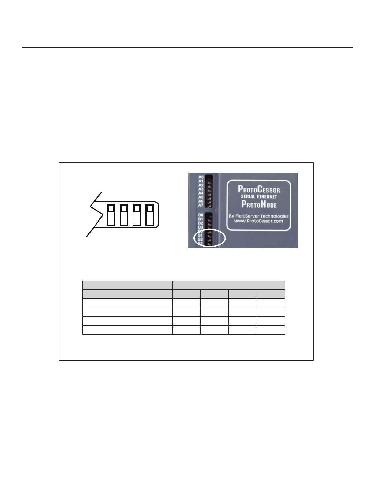
2.3 - Select eld protocol
2.3.1 - Using the S0–S3 bank of DIP switches
•
•
Turn S3 to On if the
ProtoNode is being installed for the rst time.
• BACnet MS/TP or BACnet/IP on a
•
•
S0 S1 S2 S3
S0–S3 DIP switches S bank DIP switch location
ProtoNode RER S bank DIP switches
Prole S0 S1 S2 S3
Metasys N2
BACnet MS/TP, BACnet/IP, Modbus/TCP, and Metasys N2 settings
for ProtoNode RER (FPC-N34 BACnet)
Figure 5: S bank DIP switches

5
WWW.BIGASSFANS.COM ©2013 DELTA T LLC ALL RIGHTS RESERVED
2.4 - Set MAC address, Device Instance, Node-ID
2.4.1 - Setting the MAC address
•
•
•
Note: Never set a BACnet MS/TP MAC Address from 128 to 255.
•
•
• When using Metasys N2 and Modbus/TCP, the A bank of DIP switches is disabled and not used. They should be set to OFF.
Figure 6: MAC address DIP switches
2.4.2 - Setting the Device Instance (Node-ID)
•
•
For example:
• Node_Oset default = 50,000
• Device 1 has a Modbus Node-ID of 1, Device 2 has a Modbus Node-ID of 2, Device 3 has a Modbus Node-ID of 3.
•
•
•
•
Note: When setting DIP switches, ensure power to the board is OFF.
WWW.BIGASSFANS.COM ©2013 DELTA T LLC ALL RIGHTS RESERVED
6
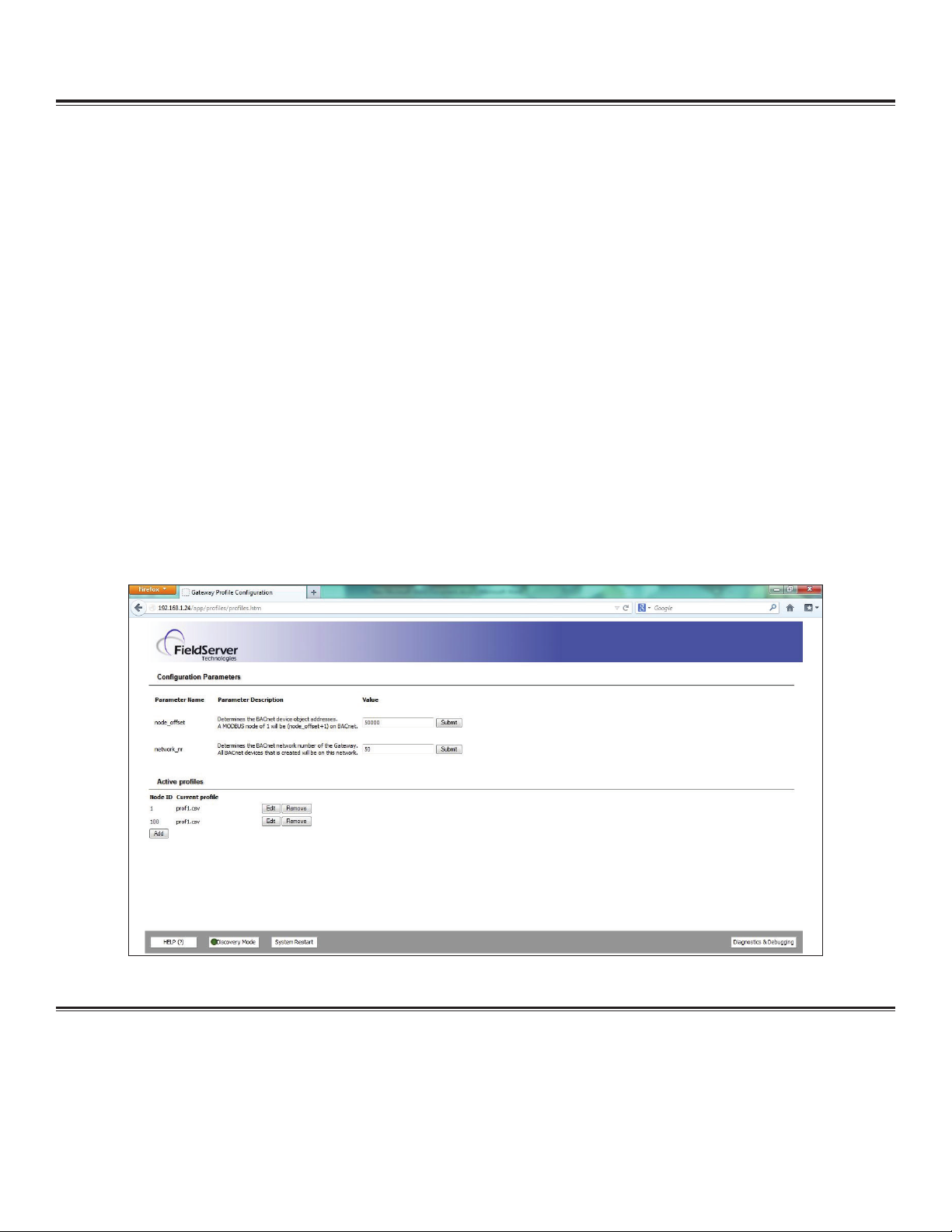
2.4.2.1 - Set Node_O
•
•
•
•
•
•
•
• Device 1 has a Modbus Node-ID of 1, Device 2 has a Modbus Node-ID of 2, Device 3 has a Modbus Node-ID of 3.
• Device 1 - Device Instance = 20,001
• Device 2 - Device Instance = 20,002
• Device 3 - Device Instance = 20,003
Note: The Modbus Node address + Node_Oset = Device Instance setting
Figure 7: FST Web GUI screen
2.4.3 - Setting the Device Node-ID
•
•

7
WWW.BIGASSFANS.COM ©2013 DELTA T LLC ALL RIGHTS RESERVED
2.5 Set baud rate
2.5.1 - Setting the serial baud rate
•
•
B0 B1 B2 B3
Figure 8: Baud rate DIP switches
2.5.1.1 - Baud rate DIP switch selection
Baud B0 B1 B2 B3
9600
19200
Figure 9: Baud rate

WWW.BIGASSFANS.COM ©2013 DELTA T LLC ALL RIGHTS RESERVED
8
RUN
ERR
RX
TX
Jumper - do not move!
Unused
Recovery button unused
or Mac address
Figure 10: ProtoNode BACnet RER
3.1 - Connection ports
3 - Interfacing ProtoNode to Devices

9
WWW.BIGASSFANS.COM ©2013 DELTA T LLC ALL RIGHTS RESERVED
Figure 12: Modbus RS-485 biasing switch on the ProtoNode N34
3.2.1 - Biasing the Modbus RS-485 network
•
one device.
•
•
• It is recommended that the biasing be left in the OFF position unless there is a problem with communicating with more
than one device. If this occurs, try setting the biasing to ON.
Figure 11: Power and RS-485 connections
Device pins ProtoNode pin # Pin assignment
V -
Frame Ground FRAME GND
3.2 - Wiring connections
ProtoNode 6-pin Phoenix connector: Pin outs to Modbus RTU products
•

WWW.BIGASSFANS.COM ©2013 DELTA T LLC ALL RIGHTS RESERVED
10
Figure 15: RS-485 EOL switch
Figure 14: Connection from ProtoNode to RS-485 eld protocol (BACnet MS/TP)
BMS RS-485 wiring ProtoNode pin # Pin assignment
-
3.3 - Wiring ProtoNode RER to RS-485 eld protocol
•
•
•
Figure 13: Modbus RS-485 end-of-line termination switch on the ProtoNode N34
3.2.2 - End-of-line termination switch for the Modbus RS-485 port on the ProtoNode
•
•
•
• Always leave the single red jumper in the A position.

11
WWW.BIGASSFANS.COM ©2013 DELTA T LLC ALL RIGHTS RESERVED
Figure 17: Power connections
Power to ProtoNode ProtoNode pin # Pin assignment
V -
Frame Ground FRAME GND
Note: These values are "nominal" and a safety
margin should be added to the power supply
of the host system. A safety margin of 25% is
recommended.
Figure 16: Required current draw for the ProtoNode
Current draw type
ProtoNode family 12VDC/VAC 24VDC/VAC 30VDC
170mA 100mA
100mA
3.4 - Wiring power to the ProtoNode
Make sure the S3 DIP switch is in the On position to enable the ProtoNode “Auto Discovery” mode for RS-485 devices
connected to the ProtoNode. See Section 4 before powering up.
Power requirements for ProtoNode at 9V through 30VDC or 12–24VAC

WWW.BIGASSFANS.COM ©2013 DELTA T LLC ALL RIGHTS RESERVED
12 4 - Run Setup for Connected RS-485 Devices
4.1 - Run Auto Discovery
• make sure power is o when
setting the switch).
•
• After the ProtoNode has discovered all of the Modbus RTU devices, set the S3 DIP switch to the OFF position to turn o.
•
•
ProtoNode RER
S3 DIP switch Auto Discovery mode S3
Figure 18: S3 DIP switch setting for Auto Discovering devices

13
WWW.BIGASSFANS.COM ©2013 DELTA T LLC ALL RIGHTS RESERVED
5 - Run Web Congurator
5.1 - Connect PC to ProtoNode via Ethernet port
Figure 19: Ethernet port location
Ethernet
1.
2. 192.168.1.24255.255.255.0
3. Start >Control Panel >Network Connections.
Local Area ConnectionProperties.
Internet Protocol (TCP/IP)Properties.
6. Select Use the following IP address:
7. OK
5.2 - Congure proles in ProtoNode's Web Congurator
5.2.1 Selecting the device proles that will be connected to the ProtoNode
Add
Figure 20: Web congurator showing the active Modbus RTU proles to select from

WWW.BIGASSFANS.COM ©2013 DELTA T LLC ALL RIGHTS RESERVED
14
Figure 21: Web Congurator showing an active Modbus TCP prole selected
Add
Figure 22: Web Congurator showing a completed prole added
Figure 23: Web Congurator showing completed proles added
6 - Restarting the Installation
1.
2. Clear Proles and Restart.
Table of contents


