Bin Master Smart Sonic User manual

Smart Sonic
Ultrasonic Transmitters
Instruction Manual
925-0156 Rev 1

2
Table of Contents
Contact Information……...…………………………….……..3
General Specifications……………………………………….4
Operation………………………………………………………5
Wiring…………………………………………………………..6
Calibration………………………………….…………………7
Mounting………………… …..……………………………….8
Technical Specifications……………………………………..9
SmartSonic 2

3
Contact Information
Customer Service and
Technical Support Personnel
Robin Kozisek
Customer Service/Order Entry
Matt Virgillito
Application Specialist
Nathan Grube
Application Specialist
Todd Peterson
Sales Manager
Dave Etherton
Technical Support
Customer Service Hotline
Call or Fax one of the following numbers if you have
installation or application questions.
1-800-278-4241 8:00 am —5:00 pm CST
(402) 434-9102 Voice
(402) 434–9133 Fax
www.binmaster.com
Division of Garner Industries
PO Box 29709 / Lincoln, NE 68529 / 7201 North 98th St. / Lincoln, NE 68507
Phone: 800-278-4241 or 402-434-9102 / Fax: 402-434-9133
SmartSonic 3

4
Conduit Entry:
1/2” NPT (PVC conduit only)
Enclosure:
PVC-94VO
Enclosure Rating:
NEMA 4X(IP65)
Temperature: -40 to +140° F (-40 to 60° C)
Pressure:
1 bar
Approvals: Entela—CSA/UL
Accuracy:
+/-0.25% of maximum range
Beam Angle:
6°-12° conical at –3dB
Loss of Echo: Hold 30 seconds, 22 mA
Temperature Compensation:
Continuous in transducer
Temperature Sensor failure: 23 mA
Calibration: Push-button or programmable via optional communication port
Diagnostics:
Via communication port (echo profile, echo stability, operation errors)
Power AC: AC units 115 VAC 60Hz or 230 VAC 50Hz, 1.7 VA
Power DC 3 Wire:
DC 2 Wire Loop Powered:
DC units 12 to 30 VDC, 0.07 A max @ 24 VDC
DC Loop Powered units, 12 to 28 VDC, 0.025 A max @ 24 VDC
Output:
4-20 mA, optional RS-232, RS-485, or Modbus
4 to 20 mA Max. Loop Resistance 110 VAC @ 750 Ohms (isolated)
12 VDC @ 250 Ohms
24 VDC @ 750 Ohms
General Specifications SmartSonic 4

5
Operation
The new SmartSonic transmitter features high efficiency, narrow beam design technology using a wide frequency bandwidth
to enhance operation in difficult applications. The transmitter performs particularly well in harsh environments where vessel
temperatures vary. SmartSonic uses smart signal processing to eliminate unwanted echoes from tank walls, standpipes,
and other tank structures that often cause error readings by other ultrasonic devices. The unit’s transducer uses a built-in,
self-cleaning operation to eliminate buildup or condensation. SmartSonic’s sensor probes are designed to adapt to the
internal tank conditions, automatically adjusting power and receiver sensitivity to any distance and reflecting surface. This
technology ensures the same echo is maintained over the entire operating range which enhances measurement accuracy.
The transmitter can be programmed to simply send a 4-20 mA analog output signal directly to an existing control system or
send data by RS-232 or RS-485 to a PC running SmartSonic’s calibration/data logging software program.
SmartSonic 5

6
Interconnecting Wire Diagram
DC Power input
Note—TB #7 is
Connected to TB #4
Control Panel
Fastening Screw
Terminal Block
Status LED
Calibration
Pushbutton
8
L1 120 VAC
Ground
L2 Neutral
4 to 20 mA +
4 to 20 mA -
DC Power
Supply
12—30 VDC
+-
4 to 20 mA -
4 to 20 mA +
AC Wire Diagram
DC 3 Wire Diagram
1/2” Conduit NPT
Conduit Connection
Wire/Cable for AC Units
115/230 VAC…………..3 wire unshielded, 22AWG (7X30), 300V
4-20 mA………………..1 pair shielded, 24AWG (7X32), 300V
Wire/Cable Recommendation for 3—Wire DC Units
24 VDC + 4-20 mA…….3 wire shielded, 24AWG (7X32), 300V
SmartSonic 6
NOTE: When installing the SmartSonic in
locations where moisture or moist air could
enter the enclosure through the electrical
conduit, use a duct seal compound to seal
the conduit opening.

7
Operation—An acoustic pulse is transmitted from the SmartSonics sensor face. The pulse travels to the surface being
monitored and is reflected off this surface back to the sensor face. The time of flight is divided by 2 and converted to an
output signal directly proportional to the material level.
Calibration Pushbutton/ LED
Indicator for 4—20 mA (750
ohm max.) Output
Deadzone FULL
20 or 4 mA
Yellow
Red
EMPTY
4 or 20 mA
6° to 12°
Span Material Level
Full—Calibration 20 mA or 4 mA (set near target)
1. Calibration mode LED color
2. Push button
Hold for 3 seconds (20 mA) until LED turns
or hold for 7 seconds (4 mA) until LED turns
3. Release button, observe, LED flashes to
acknowledge
Empty—Calibration 4 mA or 20 mA (set far target)
1. Calibration mode LED color
2. Push Button
Hold for 7 seconds (4 mA) until LED turns
or hold for 3 seconds (20 mA) until LED turns
3. Release button, observe, LED flashes to
Calibration—4-20 or 20-4 mA Output
SmartSonic 7
Green
Yellow
Red
Green
Red
Yellow
2 Wire DC 4/20 mA Loop Powered
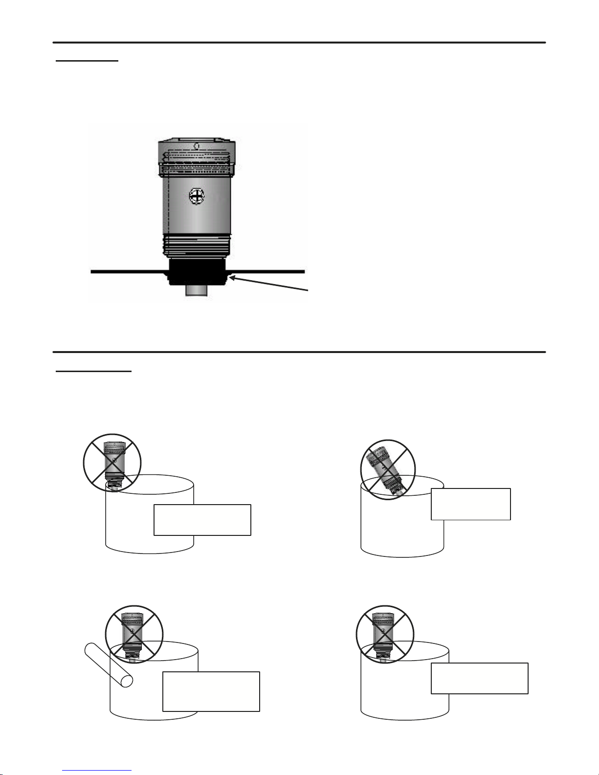
8
Avoid interference
from side of vessel
Do not install at
an angle
Avoid interference
from obstructions in
vessel
Will not operate in a
vacuum
Vacuum
Mounting:
Mounting the SmartSonic Transmitter is critical to the
proper operation of the unit. The unit can be directly
mounted by simply threading the sensor directly into a
metal or plastic mounting flange. If an extended standpipe
is used for mounting, please consult the factory for
assistance. The thread size of the unit is dependent upon
thespecificmodel(seespecifications).
Threaded Mounting Flange (1”, 1 1/2”, 2”, or 3” NPT)
Mounting
Positioning
SmartSonic 8
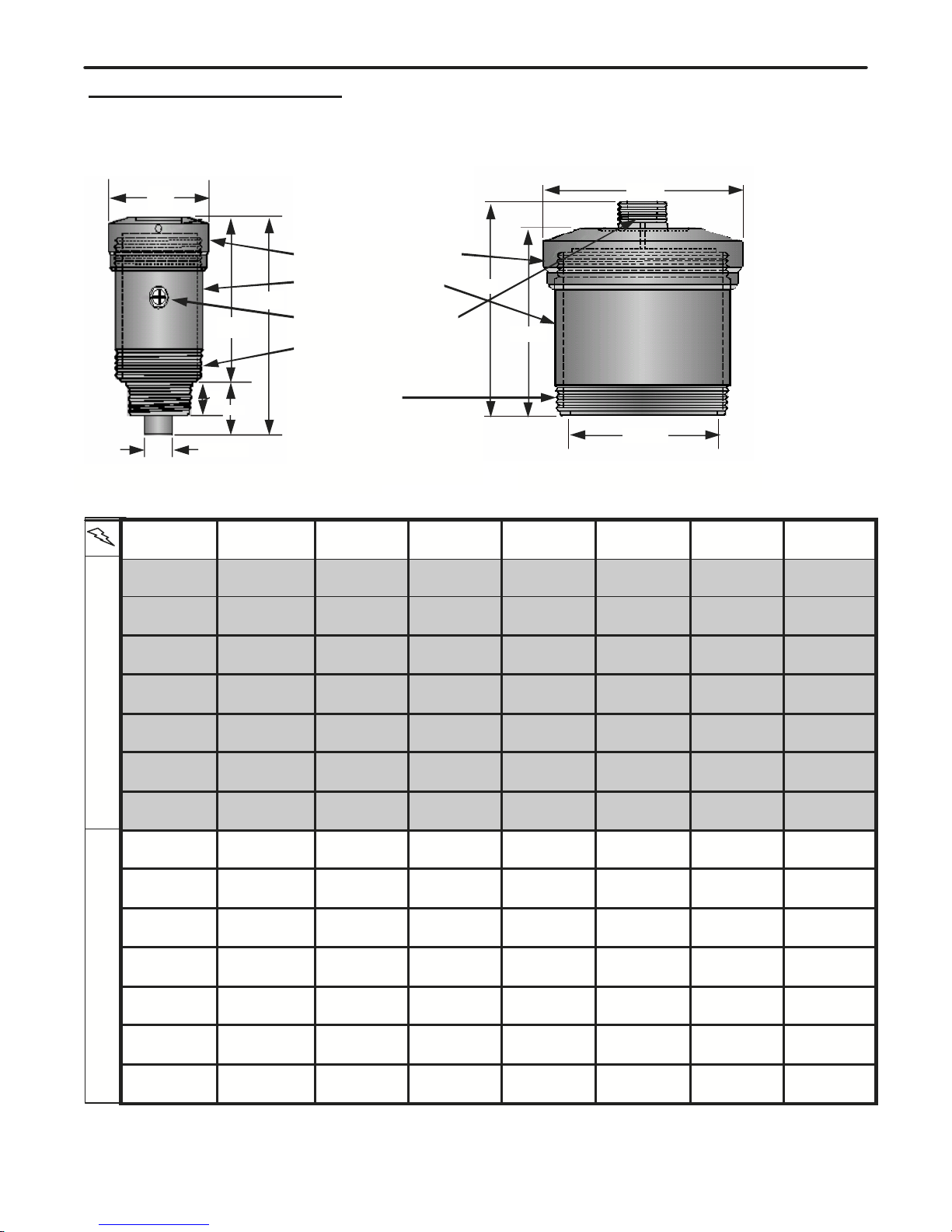
9
110/230 VAC—4 Wire
4” Ø
6.2”
‘A’
1”
DIA. ‘C’
‘B’
7.3” Ø
‘A’
6.625”
DIA. ‘C’
Threaded Access Cover
Electronic Enclosure
1/2” NPT Conduit Entry
3” NPT Thread Located on
Enclosure
6” NPT Thread
Model SS300/400-25U OnlyModels SS300/400-45U,52U,70U,80U,81U,and 148U
12 to 30 VDC—3 Wire
MODEL RANGE RESOLUTION MOUNTING
SS400-45U 1.0—60ft
0.30—18.2 m 0.19”
5 mm 3.0”
NPT
SS400-52U 0.9—50ft
0.27—15.2 m 0.16”
4 mm 3.0” or 2.0”
NPT
SS400-70U 0.8—30ft
0.24—9.1 m 0.12”
3 mm 3.0” or 2.0”
NPT
SS400-81U 0.6—16ft
0.18—4.9 m 0.08”
2 mm 3.0” or 1.5”
NPT
SS400-148U 0.4—9ft
0.12—2.7 m 0.04”
1 mm 3.0” or 1.0”
NPT
SS300-45U 1.0—60ft
0.30—18.2 m 0.19”
5 mm 3.0”
NPT
SS300-52U 0.9—50ft
0.27—15.2 m 0.19”
5 mm 3.0”
NPT
SS300-70U 0.8—30ft
0.24—9.1 m 0.12”
3 mm 3.0” or 2.0”
NPT
SS300-80U 0.7—20ft
0.21—6.1 m 0.08”
2 mm 3.0” or 2.0”
NPT
SS300-81U 0.6—16ft
0.18—4.9 m 0.08”
2 mm 3.0” or 1.5”
NPT
SS300-148U 0.4—9ft
0.12—2.7 m 0.04”
1 mm 3.0” or 1.0”
NPT
SS400-80U 0.7—20ft
0.21—6.1 m 0.08”
2 mm 3.0” or 2.0”
NPT
SS400-25U 1.4-90ft
0.40-27.4 m 0.41”
10 mm 6.0”/1.0”
NPT
SS300-25U 1.4-90ft
0.40-27.4 m 0.41”
10 mm 6.0”/1.0”
NPT
OPERATING
FREQUENCY
25 KHz
45 KHz
52 KHz
70 KHz
80 KHz
81 KHz
148 KHz
25 KHz
45 KHz
52 KHZ
70 KHZ
80 KHz
81 KHz
148 KHz
DIMENSION
‘A’
7.625”
8.9”
9.3”
8.5”
8.5”
8.4”
8.25”
7.625”
8.9”
9.3”
8.5”
8.5”
8.4”
8.25”
DIMENSION
‘B’
N/A
3.0”
3.05”
2.25”
2.25”
2.1”
2.0”
N/A
3.0”
3.05”
2.25”
2.25”
2.1”
2.0”
DIMENSION
‘C’
5.75”
3.0”
2.2”
1.8”
1.8”
1.5”
1.1”
5.75”
3.0”
2.2”
1.8”
1.8”
1.5”
1.1”
Technical Specifications SmartSonic 9

10
4” Ø
4.75”
‘A’
1”
DIA. ‘C’
‘B’
Threaded Access Cover
Electronic Enclosure
1/2” NPT Conduit Entry
3” NPT Thread Located on
Enclosure
Models SS200-70U,80U,81U,and 148U
2 Wire -4/20mA Loop Powered
MODEL RANGE RESOLUTION OPERATING
FREQUENCY MOUNTING DIMENSION
‘A’ DIMENSION
‘B’ DIMENSION
‘C’
SS200-70U 0.8—30ft
0.24—9.1 m 0.12”
3 mm 70 KHz 3.0” or 2.0”
NPT 7.05” 2.25” 1.8”
SS200-80U 0.7—20ft
0.21—6.1 m 0.08”
2 mm 80 KHz 3.0” or 2.0”
NPT 7.05” 2.25” 1.8”
SS200-81U 0.6—16ft
0.18—4.9 m 0.08”
2 mm 81 KHz 3.0” or 1.5”
NPT 6.95” 2.1” 1.5”
SS200-148U 0.4—9ft
0.12—2.7 m 0.04”
1 mm 148 KHz 3.0” or 1.0”
NPT 6.8” 2.0” 1.1”
Table of contents
Popular Transmitter manuals by other brands


Crestron
Crestron DigitalMedia DM-TX-100F Operation guide

Hallicrafters
Hallicrafters HT-44 Operating and service instructions

Vega
Vega VEGABAR 83 operating instructions

Crestron
Crestron DM-TX1-4K-C-1G Use & care guide

ATI Technologies
ATI Technologies UniSens A12 Series manual

Nortek
Nortek korus Baton Getting started guide


