Binartec Melton MTC103 User manual

Wi-Fi-enabled thermostat-weather station
MTC103
MANUAL
EN

binartec.com
MTC103 Manual EN Rev 1.0
2
Contents
Intended Use.......................................................................................................................................... 4
Getting started....................................................................................................................................... 5
Web interface......................................................................................................................................... 6
Connection to the web interface........................................................................................................ 6
Web interface description.................................................................................................................. 7
Main page overview........................................................................................................................... 8
Main page description.......................................................................................................................... 9
Sensors Setup....................................................................................................................................... 10
Weather Station Sensor Types ......................................................................................................... 10
Parameters Settings \ Sensors.......................................................................................................... 11
meltON Sensor Link (“Sharing” sensors)........................................................................................... 12
Wi-Fi Setup........................................................................................................................................... 13
Connecting to a Wi-Fi network (transfer to Station mode)............................................................... 14
AP mode setting ............................................................................................................................... 15
Weather Service Setup......................................................................................................................... 16
Using Weather Data ......................................................................................................................... 17
Setting the heating zones..................................................................................................................... 18
Zone operating modes and control relay statuses............................................................................ 19
Basic zone settings ........................................................................................................................... 20
Operational temperature ................................................................................................................. 21
Surface heating................................................................................................................................. 22
Melting............................................................................................................................................. 23
Eco melting mode............................................................................................................................. 24
Emergency mode.............................................................................................................................. 25
Logic (Zone Switching Rules) ............................................................................................................ 26
System Setup........................................................................................................................................ 27
Firmware Update ................................................................................................................................. 28
Management Setup.............................................................................................................................. 29
Connect to Telegram ........................................................................................................................ 29
Management Commands and Alert Messages ................................................................................. 31
Example No. 1 Roofing System T1, P1, M1 ........................................................................................... 32
Example No. 2 Roofing System with Weather service, M1................................................................... 33
Example No. 3 Roofing System with Weather service .......................................................................... 34
Example No. 4 Ground System T2, P1................................................................................................... 35

binartec.com
MTC103 Manual EN Rev 1.0
3
Example No. 5 Groud System T2, P1 with Weather service (3 hour weather forecast) ........................ 36
Example No. 6 Ground System T2 with Weather service (3 hour weather forecast) ............................ 37
Example No. 7 Pipe Heating System T3 ................................................................................................ 38

binartec.com
MTC103 Manual EN Rev 1.0
4
Intended Use
Wi-Fi-enabled thermostat-weather station MTC103 (hereinafter referred to as the weather station) is
designed to control cable de-icing systems for roofs, open areas, pipelines and tanks, as well as any
other cable systems intended for electrical heating.
The weather station was designed utilizing dual-core microprocessor technology using the real-time
operating system (RTOS), leading to the creation of a very reliable precipitation melting system. Using
various unique settings and algorithms, our own weather service and technology for remote access to
sensor data, we have created a flexible and efficient precipitation next-gen melting system.
The weather station can control heating systems for three independent zones.
The weather station supports the following types of sensors:
temperature sensors air, surface, sensors of atmospheric precipitation, the presence of melting water
on the roof or ground.
The weather station can operate in fully automatic mode utilizing the Internet-based weather service
(with no sensors installed or using weather service data when sensors are disconnected).
The weather station is configured and managed via the integrated web interface.
This interface allows customer to access all the functions and settings of the system remotely. It is also
possible connecting weather station to the Telegram messenger to provide alerts in real time about
different events and control the weather station operations (turning on, off heating zones, etc.).

binartec.com
MTC103 Manual EN Rev 1.0
5
Getting started
To start the weather station, please proceed as follows:
1. Connect and configure (Settings \ Sensors) the necessary sensors and / or weather service (Settings \
Weather service). Sensors can be either local, connected directly to the weather station, or remote,
receiving measurements via the Internet from sensors connected to another weather station.
2. When using the weather service and / or remote and / or local sensors measurements, transferred to
other weather stations, weather station must be connected to a Wi-Fi network with access to the
Internet. Please see more information on the corresponding page (Settings \ WiFi).
3. Set the required number of heating zones according to the requirements at the facility (Settings \
Zones).

binartec.com
MTC103 Manual EN Rev 1.0
6
Web interface
Connection to the web interface
When the device is started for the first time, it will automatically start in AP mode.
To connect to the device’s web interface for the first time (AP mode), please proceed as follows:
1. Connect to a Wi-Fi network with SSID (network name): meltON MTC103
2. In the address bar of the browser, enter the local IP of the device: 192.168.7.1
3. On the login page, enter the access password: 12345678
To connect to the device’s web interface in Station mode, please proceed as follows:
1. In the browser address bar, enter the local IP address of the weather station.
2. On the login page, enter the access password.

binartec.com
MTC103 Manual EN Rev 1.0
7
Web interface description
This device has an adaptive web interface design, which ensures its correct and convenient display on
devices with different screen resolutions, both on mobile device and personal computer.
Supported browsers: Chrome, Opera, Firefox, Safari, IE, EDGE.
The web interface is used to configure the weather station and manual control of the zones.
Web interface menu
Web Interface Pages
Main
This page displays sensor data, weather service data and operating
modes of the heating zones. It is possible to manually turn on / off
the zone control relay. Allows activation and deactivation of all
heating zones of the system.
Status
This page displays current system configuration parameters,
including:
- Name of the weather station model
- Wi-Fi signal strength (relevant only for Station mode)
- MAC address of the weather station
- Current time
- Uptime after last power on or reboot
- Status of Internet connection (relevant only for Station mode)
- The temperature inside the micro-controller of the weather station
- Amount of free RAM memory
Consumption
This page allows viewing graphs of the estimated energy
consumption and operating time of the heating system.
Settings \ Sensors
This page allows you to configure weather station sensors.
Settings \ Zones
This page allows you to configure heating zones.
Settings \ Weather Service
This page allows you to configure the weather service.
Settings \WiFi
This page allows you to configure Wi-Fi and select its modes of
operation.
Settings \ System
This page allows configuring the TCP port of the web interface, web
interface language, updating firmware of the weather station,
updating password for web interface accessing, selecting time zone,
resetting all system settings to factory defaults, and restarting the
weather station.
Settings \ Management
This page allows configuring remote control and connection to the
Telegram messenger.
binartec.com
MTC103 Manual EN Rev 1.0
8
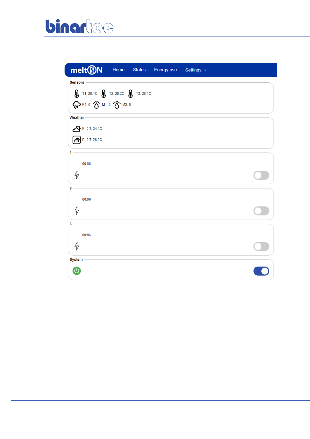
Main page overview
This page displays the current status of the system: readings of sensor measurements, weather
data, current operating modes of the heating zones. Additionally, this page allows forcing the
heating of zones using the Manual mode.
In Manual mode, zone control relay will be in the on state for the time specified in the zone
setting. In emergency situations, it is possible to quickly turn off the operation of all zone modes,
using a switch in the System section: after this switch is deactivated, the control relays of all zones
will remain off until the next system activation.

binartec.com
MTC103 Manual EN Rev 1.0
9
Main page description
Sensors
The current sensor values and operation
status are displayed. If the sensor fails,
the value is displayed as E.
Example: T1: E
(Only activated sensors are displayed,
this section is displayed if at least one
sensor is activated)
Weather
service data legend
current weather
3 hours ahead weather
forecast
P: precipitation
0-no precipitation; 1-weak; 2-moderate;
3-strong; 4-very strong
T: air temperature
(this section is displayed if weather
service is enabled)
Zone
current status of the zone
current zone mode
current status of the zone
control relay
enable / disable manual
mode
operating time of the
mode \ remaining
operating time of the
mode
mode operation time
System activated
the system is operational.
System deactivated
all zones are off, all control relays are off

binartec.com
MTC103 Manual EN Rev 1.0
10
Sensors Setup
When utilizing sensors, proper device installation and connection is essential. Installation
recommendations as well as the wiring diagram can be found in the Installation Guide.
Weather Station Sensor Types
T1
Temperature sensor No. 1 (temperature of air, ground or pipe surface).
T2
Temperature sensor No. 2 (temperature of air, ground or pipe surface).
T3
Temperature sensor No. 3 (temperature of air, ground or pipe surface).
P1
Precipitation sensor with internal heating element.
The sensor has a temporary hysteresis of 30 seconds.
M1
Roof sensor, determines the presence and level of moisture on the roof and in the
gutters.
M2
Roof sensor, determines the presence and level of moisture on the roof and in the
gutters.
M2
Ground sensor, determines the presence and level of moisture on the ground.
Prior to utilizing sensors, please activate the necessary sensors (page Setup \ Sensors). Current sensor
data and status is displayed on the Home page. The E value of the sensor indicates an error, or the
sensor is in a malfunctioning state.
Precipitation and moisture sensor readings
Sensors
Value
Description
0
Dry, no precipitation or moisture.
1
Light rainfall or moisture.
2
Average rainfall or moisture.
3
Heavy rainfall or moisture.
4
Very high levels of precipitation or moisture, the entire contact
surface of the sensor is covered with water.
E
Error, sensor defective, cable break, etc.

binartec.com
MTC103 Manual EN Rev 1.0
11
Parameters Settings \ Sensors
Parameter
Range
Air temperature sensor
The air temperature sensor is indicated. Sensor measurement values
used for heating control algorithms for precipitation and soil sensor.
OFF;T1;T2;T3
Default: ON
Temperature Unit
Indicate the units the temperature value will be displayed.
°С or °F
Default: °С
Connection
Indicates type of sensor connection. When the connection value is
OFF, this sensor is not used by the system and is not displayed on the
main page.
Local - the sensor is directly connected by a cable to the weather
station.
Remote - the sensor for this weather station is remote, this weather
station receives sensor measurements from another weather station
via the Internet.
OFF; Local; Remote
Default: OFF
Sharing
This switch activates sensor sharing technology. The measurement
values of this sensor will be transmitted via the Internet to other
weather stations.
OFF;ON
Default: OFF
Remote address
MAC address of the remote weather station (the MAC address is
displayed on the Status page of the remote weather station).
If the weather station does not receive data for more than 20
minutes, this sensor displays a status E.
Heating temperature
The lower temperature threshold that will trigger the internal heating
element of the sensor to switch on. The temperature value is received
from the air temperature sensor. If the air temperature sensor is not
specified or is in a malfunctioning state, the heating element of the
sensor is always on.
0°С…10°С
Default: 5°С
The Kind
Selecting a connected sensor: roof or ground
Roof or Ground
Default: Roof
To save the settings, click the Save button.
binartec.com
MTC103 Manual EN Rev 1.0
12
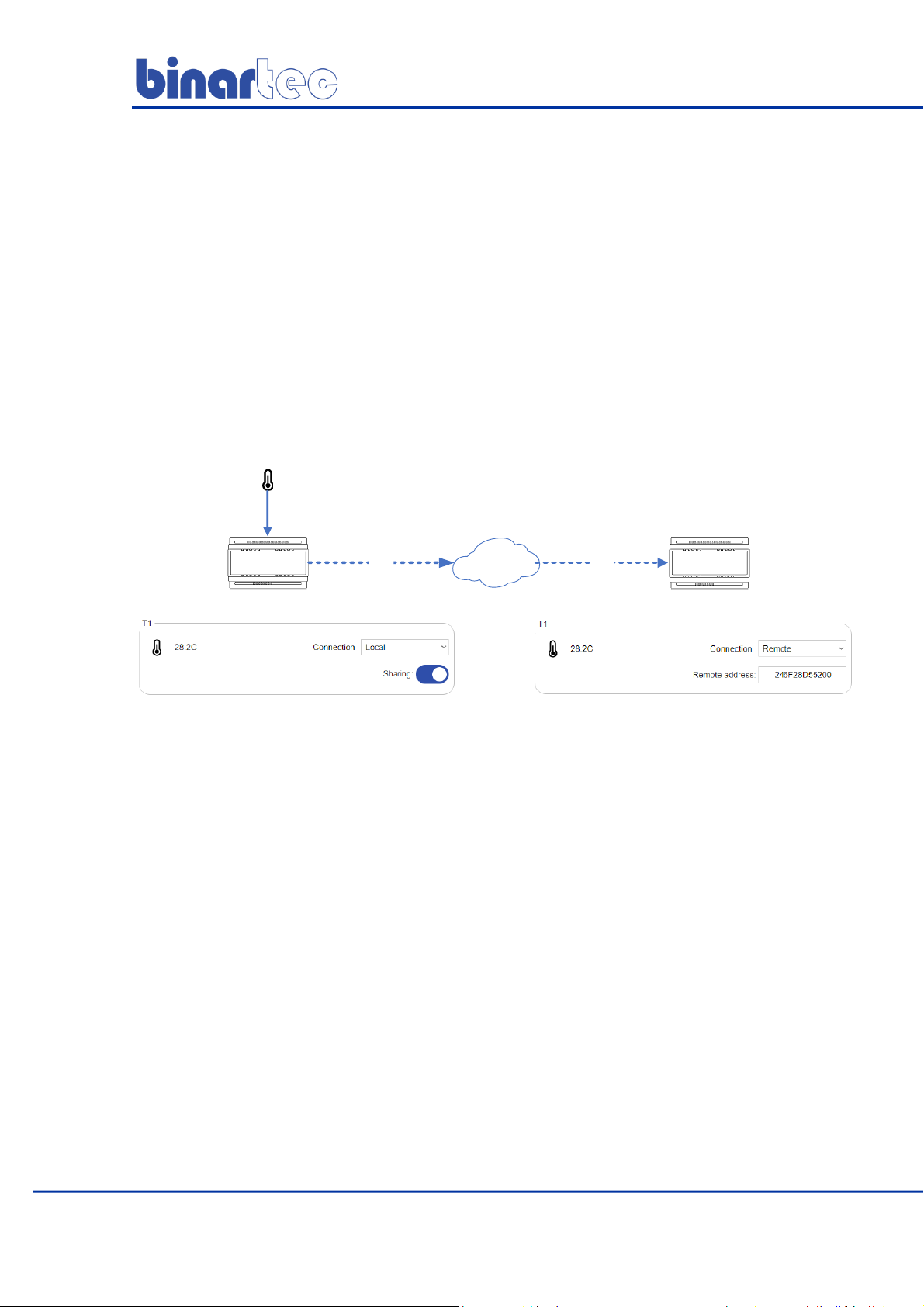
meltON Sensor Link (“Sharing” sensors)
This technology allows sharing sensor measurement values from one weather station with local cable-
connected sensors with unlimited number of other weather stations using the Internet. It is a
convenient way to optimize expenses for facilities that consist of multiple buildings: it is enough to
install a precipitation sensor and air temperature sensor connected to weather station only on a single
building. Weather station(s) on other buildings of the same group will receive sensor measurements
information via the Internet without the need to install local sensors.
Example:
Weather stations 1 and 2 are installed at different sites. A temperature sensor is connected to weather
station 1 to port T1, weather station 2 receives T1 sensor data from weather station 1 via the Internet.
See settings and operation diagram in the figure below:
1
MAC:246F28D55200
WiFi WiFi
12
INTERNET
T1
binartec.com
MTC103 Manual EN Rev 1.0
13
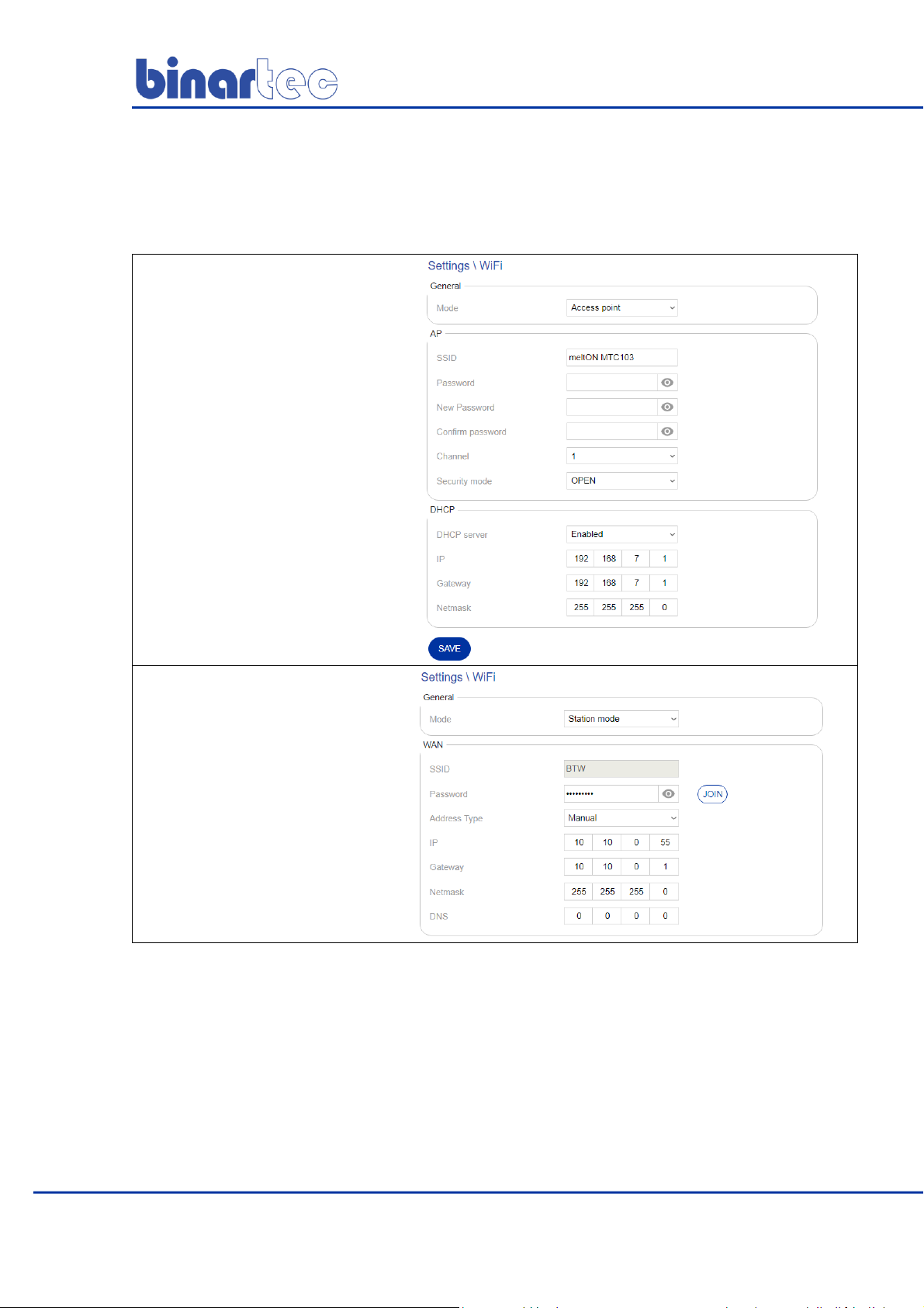
Wi-Fi Setup
The Settings \ WiFi page allows configuring the device to work in either Station mode or AP mode.
The recommended minimal level of Wi-Fi RSSI signal is at least -70.
AP access point mode -
autonomous operation mode
without connecting to the
Internet and a router (in this
mode, the weather station
creates its own Wi-Fi network).
Station mode –
operation mode that allows
connecting to another Wi-Fi
network and the Internet.

binartec.com
MTC103 Manual EN Rev 1.0
14
Connecting to a Wi-Fi network (transfer to Station mode)
To connect weather station device to a Wi-Fi network and the Internet, please proceed as follows:
1
Go to the Settings \ WiFi page
2
Set Station mode in the drop-
down list
3
Click Scan
4
From the list of the available
Wi-Fi networks locate the one
you want to use and click on the
Join button
5
Enter the password for the
selected Wi-Fi network and press
the button Join to connect.
If necessary, please set type of
address to Manual when setting the
local IP address of the weather
station. If a DHCP server is disabled
on the router, please use this type of
address and specify all other
parameters (IP, Gateway, Netmask)
manually.
6
Please make sure to remember or
write down new local IP address
of the weather station that
appears in the screenshot, like
the one on the right. This IP
address should be utilized for
further access to the web
interface.
Click the Save button. The device
will save the new Wi-Fi settings
and reboot. After rebooting the
device, please use new local IP
address for the web interface
access. Reboot can take up to 30
seconds.

binartec.com
MTC103 Manual EN Rev 1.0
15
AP mode setting
SSID –The name of the Wi-Fi network of the
weather station (Latin characters are
recommended)
Password –The password for accessing the Wi-
Fi network of the weather station
Channel –channel Wi-Fi network weather
station
Security mode –Wi-Fi network security type of
the weather station
DHCP –weather station DHCP server settings
IP –local IP address of the weather station in
AP mode

binartec.com
MTC103 Manual EN Rev 1.0
16
Weather Service Setup
The weather service uses data from more than 200,000 ground stations located around the world and
satellite weather radar data. This allows you to get accurate weather information.
To use the system on the ground or to heat pipes, you must use a soil temperature sensor
or pipe surface sensor.
The weather service is configured on the
Settings \ Weather Service page. On this page,
please indicate on the map the exact
installation location of the weather station (for
the weather service to work correctly) and
enable the weather service using the Enable
Weather Service switch.
To check the operation of the weather service
after its inclusion, go to the Home page and the
Weather section will appear. This section will
hold weather data that will be updated after
activation with an about a minute delay. To
save the settings, click the Save button.
In the absence of weather service data for more than 3 hours, the weather station will consider the
weather service unavailable and will reflect this on the main page. The zone will go into emergency
mode (when using the weather service in the heating zone).
To check the operation of weather station algorithms and zone settings, it is possible to enable the Test
mode. To proceed with that, please turn on the Weather service testing switch. It will enable sending
arbitrary weather conditions to this weather station via the Internet using special software.

binartec.com
MTC103 Manual EN Rev 1.0
17
Using Weather Data
The weather service provides the following data: air temperature, precipitation, etc.
To use the weather service data, you must activate it for the zone.
There are the several rules for using weather service data (provided that the weather service is activated
for the zone and included in the system):
1. If the sensor selection field is set to OFF or WS, and the Heating temperature field is set to WS, the
weather service data is used instead of the sensor data. Weather service will be the main and only data
channel for the sensor of that selected zone.
For example:
OFF or WS is set in the temperature sensor field, and WS in the heating temperature field, the system
will utilize the air temperature forecast by the geographical location of the weather station.
OFF or WS is set in the precipitation sensor field, OFF or WS is set, and WS in the heating temperature
field, the system will utilize the precipitation level forecast by the geographical location of the weather
station.
2. If a value other than OFF or WS is indicated in the sensor selection field, and a value other than WS is
indicated in the Heating temperature field, the data of the selected sensor will be utilized while sensor is
in working condition. If the sensor fails, the system replaces its data with the weather service data.
Weather service in this case is a backup data channel.
Additionally, weather station will allow configuring one or more heating zones to work utilizing sensor
data, and the other zone(s) to work utilizing weather services data.

binartec.com
MTC103 Manual EN Rev 1.0
18
Setting the heating zones
The weather station provides operation from one to three independent heating zones for different
systems and their combinations.
Example 1
Zone 1–roofing system
Zone 2–ground system
Zone 3–pipe system
Example 2
Zone 1–roofing system
Zone 2–ground system
Zone 3–ground system
Example 3
Zone 1–roofing system
Zone 2–roofing system
Zone 3–roofing system
It is also possible to configure dependent on / off zones: when turning on one of the zones will turn on
another zone, etc. This function can be used for 2 or 3-step inclusion of a zone.
The operation of all heating zones is configured on the Settings \ Zones page.
Zone setting is carried out by activating the necessary operating modes. That provides customers with
flexibility and ease of zone setup for different systems.
Heating zones settings can be transferred between different weather stations. For that purpose, please
use the Download and Download buttons on the Settings \ Zones page.

binartec.com
MTC103 Manual EN Rev 1.0
19
Zone operating modes and control relay statuses
Stand By mode
In this mode, the zone control relay is off. Sensor and weather
data are acquired.
Manual mode
The operation of the system is carried out regardless of the state
of the connected sensors and weather service data. Enabling /
disabling manual mode is performed on the Home page. The
operating time of this mode is indicated in the zone setting.
Heat
In this mode, the surface is heated to a predetermined
temperature using the Heating temperature parameter. Zone
control relay is on.
Melting
In this mode, snow and ice melt from the roof or heated surface.
Zone control relay is on. System can also operate in Eco-mode in
cycles, saving energy.
Additional heating
After the readings of the sensor (s) of precipitation / roof / soil or
weather service have reached a dry state or less than a specified
level, the system will maintain heating for the time period
specified on the Settings \ Zones page. System can also operate in
Eco-mode in cycles, saving energy.
Emergency mode
This mode is activated if the system does not receive any data
from sensors and / or weather services. Operation in this mode
occurs in cycles to save energy.
Logics
This mode shows that the zone was turned on when another zone
was turned on, according to the setting of Zone Switching Rules
Control Relay Statuses
ON (control relay is on)
OFF (control relay is off)

binartec.com
MTC103 Manual EN Rev 1.0
20
Basic zone settings
This section describes the main parameters
of the zone.
Parameter
Range
Name
Set a custom zone name (displayed on the main page)
Up to 32 characters
Rated power (kW)
Used to calculate and plot energy consumption graphs on the Energy
Consumption page.
0 ... 300kW
Zone On Delay (sec)
Zone relay enable delay. Time is considered only from the last time the
relay of another zone was turned on.
0 ... 1440 seconds
(24 minutes)
Default: 5 seconds
Manual operation time (min)
Manual operation time. Turns on / off on the main page. If set to 0,
manual mode is disabled.
0 ... 1440 minutes
(24 hours)
Default: 0 minutes
Weather service
(Activate the Weather Service switch in the zone switch)
When activating the weather service in the zone, the weather station can
use its data in the following scenarios:
- Basic weather service. If all the sensors in the zone are in the OFF
position, then the weather station uses only weather service data for
operation. If within 3 hours the weather service data is not available, the
system will go into Emergency mode, if it is activated, or turn off the
control relay.
- Back-up weather service. If the weather service is activated and the
sensors are selected, then the weather station operates according to the
sensors. When a sensor fails, the weather station starts using “missing
sensor data”from the weather service.
ON/OFF
Default: OFF
Emergency mode
(Activate the switch Emergency mode on the zone)
The zone goes into emergency mode if one of the sensors selected in the
zone setup fails or the weather service becomes unavailable. When the
zone is in emergency mode, the zone control relay is turned on and off
according to the cycles specified in the Emergency mode section of this
zone (the default cycle time is 240 minutes and the cycle power is 50%,
i.e. the zone control relay will turn on for 120 minutes, then 120 minutes
off).
ON/OFF
Default: OFF
Table of contents
Popular Thermostat manuals by other brands


Computherm
Computherm E Series instruction manual

Lennox
Lennox Commercial Touchscreen Thermostat owner's guide

VDH
VDH ALFANET 55 RTDF user manual

Carrier
Carrier PERFORMANCETSERIES EDGER THERMIDISTATT CONTROL... installation instructions

White Rodgers
White Rodgers NP100 Installation instructions & user guide

Honeywell
Honeywell TH9320WF5003/U user guide


