6 | Installation and User Manual
• Measurable range: 0 – 40 °C / 32 – 99 °F
• Controllable range: 5 – 35 °C / 40 – 95 °F
• Resolution: 0.5°C / 1°F
Embedded thermistor for measuring
Room Temperature
• When temperature is below 0°C / 32°F , temperature
keeps display LO
• When temperature is above 40°C / 99°F, temperature
keeps display HI
• When sensor not connected or shorted thermostat
will show “- -“ and heat/cool output will turn OFF
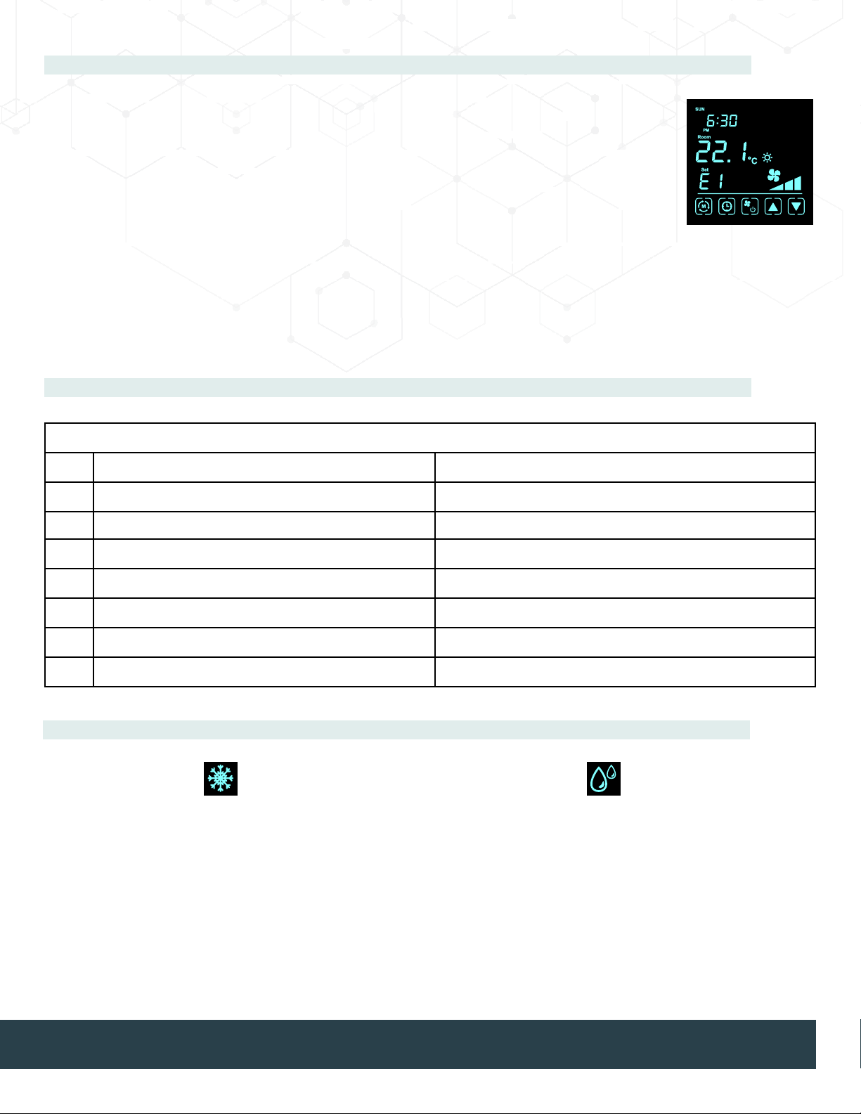
Remote water temperature
sensor
(for 2-pipe systems only)
• When 2-pipe system is selected
(2H or 2P mode), remote water
temperature sensor must be
present
• When sensor not connected or
shorted thermostat will show
"E1" and heat/cool outputs will
turn OFF
Temperature Measurement
Resolving Warning Symbols
Technical data
1. Power supply 24VAC ± 20%
2. Relay contact voltage 24VAC 50/60 Hz
3. Relay contact current 2(1)A max
4. Sensing Element 103AT
5. Terminals: 2 mm2 cable
5. Operating Temperature 32 ~ 122 °F / 0 ~ 50 °C
7. Storage Temperature 23 ~ 122 °F / -5 ~ 50 °C
8. Operating Humidity 5 ~ 95% R.H. non-condensing
Technical Data
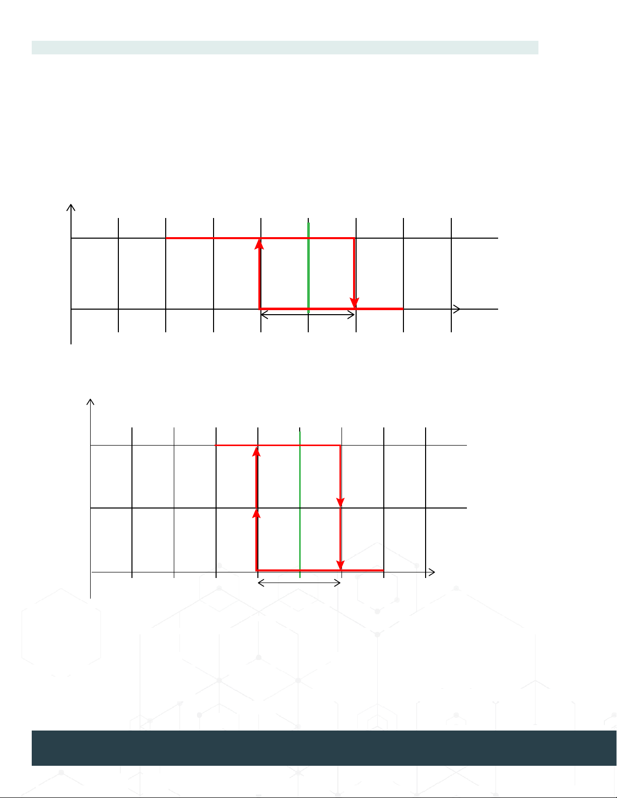
Anti-Freeze Mode Drain Pan Mode
Defrost indicator is shown on the screen when; the room
temperature is below 5 °C / 41 °F OR remote water
temperature sensor is below 1 °C / 34 °F OR 24VAC
trigger signal is ON at FZ terminal. When triggered, fan-
speed is set to Low and all water valves open (both W
and Y outputs are turned on).
2-pipe system:
Valve output (W) should be On to keep water owing.
4-pipe system:
Cool output should On and Heat output should On. (Both
W and Y outputs should be ON)
Drain Pan indicator is shown when +24VAC signal is
triggered at DP terminal. The fan is forced to OFF and
all water valves close (both W and Y outputs are turned
OFF).