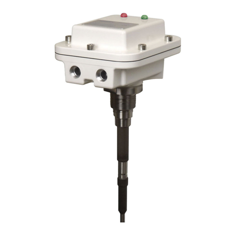
Bindicator TDR-1000 User manual

TDR180002 Rev. B
INSTALLATION,
OPERATION &
MAINTENANCE MANUAL
TDR-1000
GUIDED WAVE RADAR
Quick Start Guide
®

SAFETY INFORMATION
Before installing the TDR-1000 model, please read these instructions and familiarize
yourself with the requirements and functions. If any questions or problems arise during
the installation, please contact Bindicator®Applications at 1-800-778-9242.
The TDR-1000 model must only be installed and operated as described in this operating
instruction. Please note that other action can cause damage for which Bindicator®does
not take responsibility. If the model is not installed correctly or used in approved
applications, dangers may arise such as product overflow.
Ensure that all personnel installing, wiring, and calibrating this device are suitably
qualified.
Observe all local and national electrical codes for the wiring of this device.
The TDR-1000 level gauge is designed solely for measuring the distance, level and
volume of liquids, solids and particulate materials.
Special codes and regulations apply to its use in hazardous areas.
Responsibility as to suitability and intended use of these level gauges rests solely with
the user.
Improper installation and operation of our level gauges may lead to loss of warranty.

TABLE OF CONTENTS
1.0 Range of Use 1
2.0 Description 1
3.0 Measured Variable (distance, level, volume)
3.1 Measuring Range 1
4.0 Mounting
4.1 Excessive Bending of the Cable 2
4.2 Mounting on a Nozzle 2
4.3 Interference between two TDR's 2
5.0 Electrical Connection 3
6.0 Technical Specifications 4
7.0 Programmed Information 5

Installation, Operation & Maintenance Manual BINDICATOR®
1
1.0 RANGE OF USE
The TDR-1000 level gauging system is a 2 wire transmitter, designed to measure the distance, level and
volume of liquids, slurries, solids and particulate materials. It can be operated on storage and process
tanks.
2.0 Description
The measuring system consists of the sensor and the signal converter. The compact signal converter
contains the TDR measuring circuit and the entire signal processing system, including the provision of a
standardized output signal (4 - 20 mA or digital interface).
3.0 Measured variable (distance, level, volume)
The primary measured variable is the distance between the tank mounting flange and a reflecting surface
(surface of the product measured). The output represents the difference between the primary measured
variable and the length of the sensor.
3.1 Measuring range (to 78 ft)
The measuring range will depend on the sensor length, the reflection properties of the tanks contents, the
installation position, and the presence of any interfering reflection
4.0 Mounting, please refer to the following guidelines:
ENSURE THE SENSOR LENGTH DOES NOT
EXCEED THE INTERNAL DEPTH OF THE SILO,
TANK OR VESSEL.
Single cable
12" Min
Converter Connection
1.5 MNPT; electrical 1" G (grommet
open lead) Connection with Pressure
tight Signal feed through

BINDICATOR® Installation, Operation & Maintenance Manual
2
4.1 Excessive bending of the cable
BE CAREFUL NOT TO BEND OR KINK
CABLES TOO MUCH
4.2 Mounting on a nozzle
4.3 Interference between two TDR-1000
Avoid nozzle size higher than 5.9",
especially when B < 3.1".
Try to ensure A does not exceed B.
There must be at least 6.5ft between
devices if installed in the same vessel.
6.5 ft

Installation, Operation & Maintenance Manual BINDICATOR®
3
5.0 Electrical connection
The electrical connection for the power supply is made in the terminal compartment of the signal
converter - 18-35VDC.
In case of installation in hazardous areas, only certified intrinsically safe equipment may be
connected to the TDR-1000.
1. Connector:
Terminals: 3 poles + ground. Wire cross-section max 0.059m2(1.5 mm2) ≈(AWG 16).
pCable entries: M25x1.5 (PG11). Standard cable gland: cable clamping area = 0.315 - 0.39 in
(8-10 mm). IP65
Signal cable shielding: No shielding needed.
Power supply:
1. Remove the screw Pand lift off the connector from the signal converter.
2. Put a screwdriver in Fand separate Nfrom R.
3. Connect the current loop to terminal 1 and 2 (there’s no polarity to respect). Use ferrules to protect cable
ends. The terminal 3 and Eremain non-connected.
4. Re-assemble Nand R.
5. Put the seal in place, connect Rto the signal converter tighten and screw P.
The terminal Eis not connected with the signal connector housing or with the flange system of the instrument.
For standard and Ex applications only the intrinsically safe 2-wire loop must be connected to the terminals 1
and 2. The terminal Eas well as terminal 3 remains non-connected.
12
3
1
2
3
P
R
N
F
E

BINDICATOR® Installation, Operation & Maintenance Manual
4
6.0 Technical Specifications
Function: Level, distance and volume measurement of liquids and solids.
Measuring Range: Flexible probe: to 78ft
Deadband: Top: 15.8in Dieletric < 10
11.8in Dieletric > 10
Deadband: Bottom: 14.25in
Counter Weight Diameter.: 1.575in; length 10.25in
(Weight is tapped with 1/2" - 13 to allow tethering or anchoring)
Accuracy: +/- 0.6in
Repeatability: 0.04in
Dielectric Constant: > 2.3
Probe Materials: Flexible cable 316SS
Operating Pressure: 232 psi
Flange Temperature: -22° to 194°F
Electronics Temperature:-22° to 131°F
Connection: 1.5" MNPT
Protection Category: IP66; Nema 4X
Power Supply: 24VDC (18 to 35VDC)
Output: 4/20mA current loop into max. of 750 Ohms
Communication: HART protocol
Approvals: CE
Weight: Without probe 4.4lbs (2Kgs)
Materials of
Construction: Housing: Aluminium with white epoxy coating
Cable and Weight: 316 SS
Gaskets: Buna N
Electrical Connection
M16 CONNECTOR
Terminals: Max wire size 16AWG (1.5mm)
Cable Entries: 1 x M16 x 1.5 (with standard cable gland: cable
clamping area =0.137 - 0.315in(3.5-8mm)).
Electrical Signal Output
Electrical Connection: Two wire
Power Supply: 18 to 35 VDC
Current Output: 4/20mA
Environment
Ambient Temperature: -22° to 131°F
Protection Category to
EN 60529 / IEC 529: IP66, Nema 4X

Installation, Operation & Maintenance Manual BINDICATOR®
5
7.0 Programmed Information
CHECK LIST PARAMETERS TDR-1000 to:________________________________ Date:______________
Device No. ________________________________ Comm. No.__________________________________
Location_______________________________________________________________________________
Contact person _____________________________ Telephone__________________________________
Remarks: ______________________________________________________________________________
_______________________________________________________________________________________
Menu item_________________________________ Changed on__________________________________
Fct. Configuration parameters (customer)
1.1.1 Tank height : :
1.1.2 Dead zone : :
1.1.3 Time constant : :
1.1.6 Probe length : :
1.2.4 Length unit : :
1.2.6.1 Unit name : :
1.2.6.2 Unit factor : :
1.2.5 Volume unit : :
1.3.1 Current output, function : :
1.3.2 Current output, range/error : :
1.3.3 Min. scale for current : :
1.3.4 Max. scale for current : :
1.3.5 Error delay : :
1.4.4 Tag name : :
1.5.1 Detection delay : :
1.6.2 Address : :
Threshold : :
Fct. Configuration parameters (factory)
1.1.1 Probe type : :
1.1.2 Offset of measure : :
1.1.3 Application type : :
1.1.4 Dielectric : :
2.1 Set value of electronic offset : :
2.4 Electronic Calspeed : :
2.5 Mechanic Calspeed : :
2.6 Reference frequency : :
Fct. Strap table configuration (20 points)
Point 0 Level Volume
Point 1 Level Volume
Point 2 Level Volume
Point 3 Level Volume
Point 4 Level Volume
Point 5 Level Volume
Point 6 Level Volume
Point 7 Level Volume
Point 8 Level Volume
Point 9 Level Volume
Point 10 Level Volume
Point 11 Level Volume
Point 12 Level Volume
Point 13 Level Volume
Point 14 Level Volume
Point 15 Level Volume
Point 16 Level Volume
Point 17 Level Volume
Point 18 Level Volume
Point 19 Level Volume

BINDICATOR® Installation, Operation & Maintenance Manual
6
Notes

®
150 VENTURE BOULEVARD
SPARTANBURG, SC 29306
PHONE: 864.574.8060, FAX: 864.574.8063
CUSTOMER CARE: 800.778.9242
WWW.BINDICATOR.COM
SALES@BINDICATOR.COM
2007 ALL RIGHTS RESERVED
ALL DATA SUBJECT TO CHANGE TDR180002 Rev.B
Table of contents
Other Bindicator Radar manuals
Popular Radar manuals by other brands
Keiki
Keiki MRG-10 user guide

Escort
Escort REDLINE Cic M14R owner's manual

RIB
RIB ACG9420 manual

Endress+Hauser
Endress+Hauser FOUNDATION Fieldbus Micropilot FMR56 Brief operating instructions

RADIO HOLLAND
RADIO HOLLAND RHRS-2014 Operator's manual

Endress+Hauser
Endress+Hauser Levelflex FMP53 operating instructions

Emerson
Emerson Rosemount 3308A Reference manual

K40 ELECTRONICS
K40 ELECTRONICS Platinum 100 owner's manual

Endress+Hauser
Endress+Hauser Micropilot M FMR240 operating instructions

Radarsign
Radarsign TC-800 installation manual
SpotterRF
SpotterRF CK2B-CE quick start guide

Simrad
Simrad ARGUS FMCW 3G installation guide