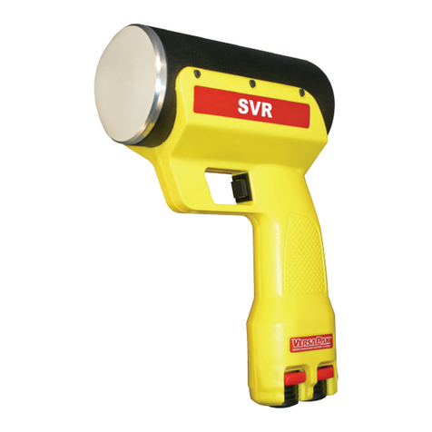
Decatur Electronics Surface Velocity Radar SVR2-01 User manual

SVR™
Surface Velocity Radar
SVR2-01
User’s Manual
Rev 12/8/2016

SVR™
Surface Velocity Radar
SVR2-01
User’s Manual

SVR™
Surface Velocity Radar
SVR2-01
User’s Manual

Table of Contents
WelcometoDecaturElectronics ...........................................6
AboutThisManual....................................................7
1 SafetyInformation....................................................8
2 ReceivingInspection..................................................9
3 GettingStarted ......................................................10
3.1 Introduction.....................................................10
3.2 BatteryCharging.................................................10
3.3 RemovingTheBatteryHolder....................................10
3.4 BatteryInstallation...............................................11
3.5 Inserting The Holder Into the SVR. . . . . . . . . . . . . . . . . . . . . . . . . . . . . . . . . 11
3.6 ChargingTheBatteries...........................................12
3.7 Charging Status Indicator (LED) . . . . . . . . . . . . . . . . . . . . . . . . . . . . . . . . . . 13
3.8 BatteryRunTime.................................................14
3.8.1 AutoPowerO................................................15
3.9 ReplacingBatteries ..............................................15
3.10 ConnectingThePowerCord.....................................15
3.11 PlugInThePowerCord .........................................15
3.12 ControlPanelFunctions ........................................15
4 Components.........................................................16
4.1 ControlButtons..................................................16
4.2 Display..........................................................17
4.3 Trigger ..........................................................19
4.4 MountingConguration.........................................19
5 OperatingModes ....................................................19
5.1 Menu............................................................19
5.1.1 Backlight......................................................21
5.1.2 DisplayFunctionCOS..........................................21
5.1.3 DisplayFunctionU.............................................22
5.1.4 DisplayFunctionA.............................................22
5.1.5 DisplayFunctionSEN..........................................23
5.1.6 High/Low Speed Selection . . . . . . . . . . . . . . . . . . . . . . . . . . . . . . . . . . . . . 23
5.1.7 Serial Port Protocol Selection. . . . . . . . . . . . . . . . . . . . . . . . . . . . . . . . . . . 24
5.1.8 SerialUpdateRate.............................................24

6 MeasuringSurfaceVelocity...........................................25
6.1 Introduction.....................................................25
6.2 TakingaMeasurement...........................................25
6.3 RecallingPreviousReadings......................................27
7 AngleCompensation.................................................29
7.1 VerticalAngleCompensation.....................................30
7.2 Horizontal Angle Compensation. . . . . . . . . . . . . . . . . . . . . . . . . . . . . . . . . . 31
8. CommunicationsPort................................................32
9 PerformanceTips ....................................................33
9.1 HowRadarWorks................................................33
9.2 Interference Sources and Remedies . . . . . . . . . . . . . . . . . . . . . . . . . . . . . . 34
9.2.1 Angular Interference (Cosine Eect) . . . . . . . . . . . . . . . . . . . . . . . . . . . . 34
9.2.2 Electromagnetic Interference (EMI) . . . . . . . . . . . . . . . . . . . . . . . . . . . . . 36
9.2.3 FeedbackInterference.........................................36
9.2.4 Radio Frequency Interference (RFI) . . . . . . . . . . . . . . . . . . . . . . . . . . . . . 36
9.2.5 Scanning . . . . . . . . . . . . . . . . . . . . . . . . . . . . . . . . . . . . . . . . . . . . . . . . . . . . . . 36
9.2.6 Environmental Factors: Wind, Rain, Snow . . . . . . . . . . . . . . . . . . . . . . . 37
10 Care,Cleaning,andStorage ..........................................37
11 Specications........................................................38
11.1 Measurement Specications . . . . . . . . . . . . . . . . . . . . . . . . . . . . . . . . . . . . 38
11.2 FactoryDefaultSettings.........................................38
11.3 AntennaParameters............................................38
11.4 Environment....................................................38
11.5 Voltages........................................................39
11.6 PowerConsumption............................................39
12 LegalRequirements..................................................40
11.1 Documents.....................................................40
13 Frequently Asked Questions (FAQ) . . . . . . . . . . . . . . . . . . . . . . . . . . . . . . . . . . . . 41
14 Warranty.............................................................43
15 ServiceReturnProcedure.............................................44
16 HowtoOrderAdditionalProducts....................................45
17 UserNotes...........................................................46


SVR2-01™User’s Manual
6
Welcome to Decatur Electronics, Inc.
Thank you for choosing this Decatur Electronics product—the SVR™,
an advanced surface velocity radar (SVR) device for measuring water
surface velocity. The SVR™ is extremely valuable for measuring water
surface velocity during high-velocity ows and ood conditions
where using contact measurement instruments poses a risk to safety.
The SVR™ incorporates many leading features such as cosine error
correction for the vertical and horizontal angle positions of the gun
to the target. The SVR™ also contains a congurable horizontal
cosine adjustment that may be used when the angle of the gun is not
parallel to the ow of the target.
If you are as pleased with its performance as we think you will be,
ask your Decatur sales representative about other Decatur products
including the Genesis™ line of radars, the Onsite™ line of speed
trailers, dollies, and pole signs and the Responder™ line of in-car
video systems.
Try any one of our products and see if you don't agree that it is the
best-in-class!
—The Management and Sta at Decatur Electronics

SVR2-01™User’s Manual
7
About This Manual
This manual contains valuable information to help you set up, use
and maintain your radar, so you can optimize its life and keep it at
peak performance. Please take a moment to read through it, and
keep it handy for future reference.
Note the following symbols in this manual:
Indicates a warning message about safety
precautions. Please read it carefully.
Indicates a helpful tip or precaution to note.
1. Safety Information
All service needs should be referred back to the manufacturer.
WARNINGS
• Donotovervoltagetheradar-itcandamagetheunit!
• WhenreplacingbatteriesintheSVR™youshould
replace all 6 with new batteries even if you suspect that
only one cell is defective.
• UserechargeableNickle-Metal-Hydridebatteriesonly.
• TheSVR™isdesignedtooperateoofconventional
+12 VDC (+10.8 to +16.5 VDC) from the power cable.
In addition, the SVR™ is also designed to operate at
7.2VDC from the internal batteries. Over voltage to the
power cables or incorrect batteries can cause damage.
WARNING
Do not put the radar gun in the water. This will
damage it. The SVR™ measures the water surface only
from outside the water.

SVR2-01™User’s Manual
8
• OpeningtheSVR™(otherthanbatteryreplacement)
automatically voids any warranty still in eect. There
are no user serviceable parts inside.
• DonotexposetheSVR™toexcessivemoisture.Never
submerge the device. If the SVR should accidentally
get submerged be sure and remove the batteries
immediately.
• DonotdroptheSVR™onhardsurfacessincedamage
could occur. Units damaged by dropping or abuse are
not covered for warranty repair.
Violation of these guidelines may void the warranty.

SVR2-01™User’s Manual
9
2. Receiving Inspection
• Whenyoureceiveyourradar,inspectallcomponentsfor
freight damage that might have happened during shipping or
unloading. Take pictures to document any damage.
• Notifythefreightcompanyimmediatelyofanydamage,
preferably while the driver is present. Record the damage on the
bill of lading and keep a record of the problems or damage.
• Thepackage should include the following pictured items along
with this User’s Manual.
SVR2-01™ Detachable power cable
Batteries & battery holder

SVR2-01™User’s Manual
10
3. Getting Started
3.1 Introduction
The SVR™ is a hand-held surface velocity radar (SVR™) gun specically
designed to measure the surface velocity of water—great for use in
streams and rivers. Features such as Recall allows you to review the
previous measurement. Other features are selectable through the
menu option.
The radar gun features a tilt sensor system, which internally
compensates for the cosine angle eect of the vertical (pitch-down)
angle of the gun to the target. It is not necessary to manually set the
tilt sensor.
3.2 Battery Charging
The SVR™ is designed to operate o of six (6) rechargeable Nickel-
Metal-Hydride batteries (or o the DC power cord). When you rst
receive your radar, the batteries will need to be charged for the rst
time before using. Once batteries have been charged if you do not
use the SVR™ for 3-4 weeks, you will want to recharge the batteries
before use in order to get the full run time. To charge batteries for the
rst time or to replace the batteries following steps 3.6 to 3.7.
3.3 Removing the Battery Holder
The battery holder is located inside the handle of the SVR™ and is
accessed by means of a sliding door. When rst received, the holder
should already have batteries installed, but if not then you will need
to remove the holder and loaded it with batteries. To remove the
battery holder slide the battery cover to the right until the battery
holder is released as shown in Figure 3.3. The door can be completely
removed from the slide.

SVR2-01™User’s Manual
11
Figure 3.3
Slide the battery door open.
3.4 Battery Installation
Insert the batteries into the battery holder following the polarity
guide that is on the inside of the battery holder (Figure 3.4a.) Once
properly loaded the battery holder will look like the example in
Figure 3.4b.
Figure 3.4b
Battery holder with batteries
Figure 3.4a
Battery holder
Notice that the negative side of each battery goes to the spring
contacts of the holder.
3.5 Inserting the Holder into the SVR™
The battery holder is designed so that it can only make contact with
the power connections inside the gun if the holder is slid into the
gun in the correct way. If you look closely at the holder you will see
that there is a positive and negative terminal on it. These need to be
inserted into the gun with the terminals located at the top as shown
in Figure 3.5.

SVR2-01™User’s Manual
12
Figure 3.5
Insert batteries.
Once the batteries have been properly loaded into the holder and
the holder has been inserted into the handle of the gun then the
door can be put back in place and slid closed. If you have not already
charged the batteries using an optional NiMH charger, you are now
ready to charge the batteries using the power cable.
• Iftheholderhasbeenplacedincorrectlyintothe
handle the door can not be put back in place and
closed..
3.6 Charging the Batteries
The power cable that comes with the SVR™ can be used to either
power the SVR™ directly from your vehicle receptacle or to charge
the SVR’s™ batteries. Once the batteries have been properly installed
into the holder and inserted into the handle plug the power cord
into the power connector at the base of the handle by aligning the
red dot on the power cord’s plug with the red dot on the connector.
Failure to align the plug with the connector properly will result
in damage to the pins of the jack. Reference Figure 3.6 for proper
alignment.

SVR2-01™User’s Manual
13
Figure 3.6
Align the dots.
Next, plug the lighter plug into an active cigarette lighter receptacle
in the vehicle. The red led on the lighter plug should come on
showing that power is being applied to the SVR™. With the SVR™
turned o, it will take approximately 2 hours to fully charge the
batteries. Turning the SVR™ on with the cord plugged in will stop the
charge cycle allowing the gun to be operated from the power cord.
Batteries do not charge when the gun is turned on.
3.7 Charge Status Indicator (LED)
The status of the charge can be determined by the Charge Status
Indicator LED located on the bottom of the handle (See Figure 3.7).
The table below denes the status.
Fast blinking green light = checking battery condition
Medium blinking green light = charging battery
Solid green light = charged
Solid red light = charging error

SVR2-01™User’s Manual
14
Figure 3.7
Charge status indicator.
The normal charging sequence is fast blink for 60 seconds, medium
blink until batteries are fully charged (approximately 2 hours for fully
discharged batteries) and solid green once batteries are charged.
The gun can be left to charge indenitely. The charging circuit will
automatically shut o once charging is complete.
• TheSVR™mustbeOFForthebatterieswillnotcharge.
You can not operate the SVR™ and charge the batteries
at the same time.
• Bestperformancefromyourbatteriesisobtainedwhen
recharged at temperature between 50ºF (10ºC) and
113ºF (45ºC). Recharging outside of that temperature
range may result in reduced battery life or incomplete
charging.
3.8 Battery Run Time
How long the SVR™ can operate between recharges depends upon
several factors including the milliamp hour (mAh) capacity of the
batteries, age of the batteries, and how the SVR™ is used. Generally
a set of 6 new 2500 mAh batteries fully charged should run for
approximately 1 week between recharges given normal use.

SVR2-01™User’s Manual
15
3.8.1 Auto Power O
If no trigger or key press is detected the SVR™ will automatically
power o after 50 minutes in order to conserve battery life.
3.9 Replacing Batteries
When replacing the batteries with new ones remember to use only
rechargeable Nickel-Metal-Hydride batteries and to replace ALL the
batteries at the same time even if you suspect that only one battery is
bad. Follow the instructions listed in steps 3.2 through 3.7 for proper
installation and charging when replacing batteries.
3.10 Connecting the Power Cord
If you choose to run o the power cord instead of the internal
batteries, connect the power cord to the receptacle on the bottom
of the SVR™ being sure to properly align the plug on the power cord
to the connector on the bottom of the SVR™. The SVR™ automatically
will switch from the internal batteries to the power cord for power
when the unit is turned on.
3.11 Plug In the Power Cord
Plug the radar’s power cord into your vehicle’s cigarette lighter
receptacle. If you are using a separate battery pack as a power source,
plug the radar’s power cord into the battery pack’s receptacle.
3.12 Control Panel Functions
The operation of the SVR™ is controlled by the ve-button key pad
and the trigger.

SVR2-01™User’s Manual
16
4. Components
4.1 Control Buttons
Figure 4.1a
Faceplate (Display and Control Buttons)
Looking at the control buttons from left to right the buttons have the
following functions:
MENU
The MENU button lets you view the options you can change.
Repeatedly pressing the MENU button advances through the
programmable features.
SEL
The select (SEL) button lets you choose the settings in each of the
mode options. To change a mode option, press the SEL button.
PWR
The PWR button turns the radar on and o. When rst powered
on the SVR™ will display the screen shown in Figure 4.1. When you
power the SVR™ o the word OFF will appear in the display and the
unit will power down.

SVR2-01™User’s Manual
17
RCL
When the recall button (RCL) is pressed the unit enters recall mode if
the following are true:
• Theunitisnottransmitting
• All10measurementshavebeencompletedandthespeedresult
has been displayed
The function is active if the letter "r" appears on the left-hand side of
the display. Up to 15 previous readings can be reviewed.
MODE
The MODE button lets you change the resolution of the display. You
can choose to have the speed displayed in 10ths or 100ths.
4.2 Display
4.2.1 Number Segments
The 5 large digits (88888) display the speed. Resolution is
determined by the placement of the decimal point. The icons
indicate the status.
4.2.2 Status Indicator Icons
When rst turned on the SVR™ performs a segment check of the
display to show that all segments and icons are working. The
following icons will appear at the top and bottom of the display
screen, however not all of the icons are for features used by the
SVR™. The icons that represent the features that are used by the
SVR™ describe the following conditions:
Figure 4.2.2
Number segments and status indicator icons.

SVR2-01™User’s Manual
18
POWER
When POWER appears, the power is on.
LOW BAT
The LOW BAT icon indicates that your internal batteries (or your
separate battery pack) may be low on power. The system will not
transmit or display any new speeds while LOW BAT appears and the
display will remain blank.
XMIT
XMIT means the radar is transmitting.
HOLD
HOLD indicates the system is not transmitting.
FPS
Indicates that the gun is set to display speeds in feet-per-second.
M/S
Indicates that the gun is set to display speeds in meters-per-
second.
Once the segment check test is completed the display will show
the POWER, HOLD and the units of measure (FPS or M/S) icons
along with 5 dashes ( - ) across the center of the display. The SVR™
is now ready to use.
Figure 4.2b
The display showing the segment check test is completed
and the SVR™ is ready to use..

SVR2-01™User’s Manual
19
4.3 Trigger
The radar transmits and receives microwave energy when you pull
the trigger. To measure the ow velocity, pull and release the trigger.
The radar will continue to transmit even though the trigger is now
released. See Section 6.2 - Taking a Measurement.
4.4 Mounting Congurations
The radar is designed for hand-held operation. Optionally, you can
mount it to a standard camera tripod.
5. Operating Modes
The MENU and SEL buttons on the SVR™ control panel lets you review
and change settings. The radar gun will remember the settings you
last set when it is turned o and will power up with them.
5.1 Menu
You can use the factory default settings or you can select your own
settings. To select a setting, repeatedly press the MENU button until
the setting you want to change appears. Then release the MENU
button and press the SEL (select) button to advance through the
selections for that setting. When you have made your selection,
release the button and your new settings will be in eect. If neither
MENU or SEL is pressed after 2 seconds, the radar gun will return
to normal operating mode, capturing whatever settings you have
selected to that point. Table 5.1 shows the menu setting choices.
• bl=Backlight(on/o)
• C=CosineAdjustment(0ºto60ºinincrementsof5º)
• U=Unitsofmeasure(Europeanmeters-per-secondor
USA feet-per-second)
• A=Angle(reportingonly)
• SEN=Sensitivity(1-10with10beingmaximumsensitivity)
• HL=HighorLowspeedranges
• SEr=SerialProtocols(Sr1andSr2)
• SErU=SerialUpdaterate(100,300,500,800or999ms)

SVR2-01™User’s Manual
20
Table 5.1
Menu Settings
Table of contents
Other Decatur Electronics Radar manuals

Decatur Electronics
Decatur Electronics GHD User manual

Decatur Electronics
Decatur Electronics SVR DUAL User manual

Decatur Electronics
Decatur Electronics Genesis VP Directional User manual

Decatur Electronics
Decatur Electronics RAILMASTER-VP User manual

Decatur Electronics
Decatur Electronics SVR DUAL User manual

Decatur Electronics
Decatur Electronics GHD User manual

Decatur Electronics
Decatur Electronics Genesis II Select Installation and operating instructions

Decatur Electronics
Decatur Electronics SI-3C User manual

Decatur Electronics
Decatur Electronics Genesis VP Directional User manual

Decatur Electronics
Decatur Electronics SI-3 User manual