Image Sensing Systems RTMS Echo User manual

RTMS Echo User Guide ©2019 Image Sensing Systems Inc.
PN A900-1280-5Rev A
RTMS Echo
User Guide

RTMS Echo User Guide ©2019 Image Sensing Systems Inc. ii
RTMS
Copyright
© 2019 Image Sensing Systems, Inc. All Rights Reserved. No part of this document may be reproduced
or quoted without written permission from Image Sensing Systems, Inc.RTMS and Echo are trademarks
of Image Sensing Systems, Inc., registered in the United States and other countries.All other product
names referenced in this guide are trademarksof their respective owners.
Record of Revisions
Revision Date Affected Pages Description
A 12/2019 Initial release.

RTMS Echo User Guide ©2019 Image Sensing Systems Inc. iii
Table of Contents
Preface- - - - - - - - - - - - - - - - - - - - - - - - - - - - - - - - - - - - - - - - - - - - - - - - - - - - - - - - - - - - - - - - - - - -vi
Federal Communication Commission (FCC) Notices- - - - - - - - - - - - - - - - - - - - - - - - - - - - - - - - - - vi
Industry Canada (IC) Notices - - - - - - - - - - - - - - - - - - - - - - - - - - - - - - - - - - - - - - - - - - - - - - - - - -vii
FCC and IC ID Numbers - - - - - - - - - - - - - - - - - - - - - - - - - - - - - - - - - - - - - - - - - - - - - - - - - - - - -vii
CE Certification - - - - - - - - - - - - - - - - - - - - - - - - - - - - - - - - - - - - - - - - - - - - - - - - - - - - - - - - - - - -vii
Chapter 1:Introduction - - - - - - - - - - - - - - - - - - - - - - - - - - - - - - - - - - - - - - - - - - - - - - - - - - - - - - 1-1
General - - - - - - - - - - - - - - - - - - - - - - - - - - - - - - - - - - - - - - - - - - - - - - - - - - - - - - - - - - - - - - - - 1-1
Features/Benefits - - - - - - - - - - - - - - - - - - - - - - - - - - - - - - - - - - - - - - - - - - - - - - - - - - - - - - - - - 1-1
RTMS Echo Technical Specifications - - - - - - - - - - - - - - - - - - - - - - - - - - - - - - - - - - - - - - - - - - - 1-2
Electromagnetic Interference - - - - - - - - - - - - - - - - - - - - - - - - - - - - - - - - - - - - - - - - - - - - - - - - - 1-3
Firmware Upgrade Capability - - - - - - - - - - - - - - - - - - - - - - - - - - - - - - - - - - - - - - - - - - - - - - - - - 1-3
Chapter 2:Pre-Installation Considerations - - - - - - - - - - - - - - - - - - - - - - - - - - - - - - - - - - - - - - - 2-1
General - - - - - - - - - - - - - - - - - - - - - - - - - - - - - - - - - - - - - - - - - - - - - - - - - - - - - - - - - - - - - - - -2-1
Safety Information - - - - - - - - - - - - - - - - - - - - - - - - - - - - - - - - - - - - - - - - - - - - - - - - - - - - - - - - - 2-1
Power Considerations - - - - - - - - - - - - - - - - - - - - - - - - - - - - - - - - - - - - - - - - - - - - - - - - - - - - - -2-1
Cabling Considerations - - - - - - - - - - - - - - - - - - - - - - - - - - - - - - - - - - - - - - - - - - - - - - - - - - - - -2-2
Breakout Boxes- - - - - - - - - - - - - - - - - - - - - - - - - - - - - - - - - - - - - - - - - - - - - - - - - - - - - - - - 2-3
Surge Suppression/Filtering - - - - - - - - - - - - - - - - - - - - - - - - - - - - - - - - - - - - - - - - - - - - - - - - 2-4
Connecting Power and Communications - - - - - - - - - - - - - - - - - - - - - - - - - - - - - - - - - - - - - - - 2-5
Providing a Proper Ground - - - - - - - - - - - - - - - - - - - - - - - - - - - - - - - - - - - - - - - - - - - - - - - - - 2-7
Placement in Side-Fired Highway Configuration - - - - - - - - - - - - - - - - - - - - - - - - - - - - - - - - - - -2-9
Height, Setback, Tilt Requirements - - - - - - - - - - - - - - - - - - - - - - - - - - - - - - - - - - - - - - - - - - 2-11
Guardrails and Barriers - - - - - - - - - - - - - - - - - - - - - - - - - - - - - - - - - - - - - - - - - - - - - - - - - 2-12
Sunken Road and Roadside Walls - - - - - - - - - - - - - - - - - - - - - - - - - - - - - - - - - - - - - - - - - 2-12
Elevated Roadway- - - - - - - - - - - - - - - - - - - - - - - - - - - - - - - - - - - - - - - - - - - - - - - - - - - - - - 2-13
Installing RTMS Echo on Sign Structures- - - - - - - - - - - - - - - - - - - - - - - - - - - - - - - - - - - - - - 2-14
Grade Differentials- - - - - - - - - - - - - - - - - - - - - - - - - - - - - - - - - - - - - - - - - - - - - - - - - - - - - - 2-15
Trees - - - - - - - - - - - - - - - - - - - - - - - - - - - - - - - - - - - - - - - - - - - - - - - - - - - - - - - - - - - - - - 2-15
Chapter 3:Sensor Installation & Setup - - - - - - - - - - - - - - - - - - - - - - - - - - - - - - - - - - - - - - - - - - 3-1
General - - - - - - - - - - - - - - - - - - - - - - - - - - - - - - - - - - - - - - - - - - - - - - - - - - - - - - - - - - - - - - - -3-1
Safety Information - - - - - - - - - - - - - - - - - - - - - - - - - - - - - - - - - - - - - - - - - - - - - - - - - - - - - - - - - 3-1
Installing the Sensor - - - - - - - - - - - - - - - - - - - - - - - - - - - - - - - - - - - - - - - - - - - - - - - - - - - - - - - 3-2
Setting Up the Sensor - - - - - - - - - - - - - - - - - - - - - - - - - - - - - - - - - - - - - - - - - - - - - - - - - - - - - -3-4
Logging in to the Sensor For the First Time - - - - - - - - - - - - - - - - - - - - - - - - - - - - - - - - - - - - 3-5
Aiming the Sensor - - - - - - - - - - - - - - - - - - - - - - - - - - - - - - - - - - - - - - - - - - - - - - - - - - - - - - - 3-6

Table of Contents
RTMS Echo User Guide ©2019 Image Sensing Systems Inc. iv
Detect and Adjust Zones - - - - - - - - - - - - - - - - - - - - - - - - - - - - - - - - - - - - - - - - - - - - - - - - - - 3-7
Verifying Vehicle Counts - - - - - - - - - - - - - - - - - - - - - - - - - - - - - - - - - - - - - - - - - - - - - - - - - 3-9
Configure Settings - - - - - - - - - - - - - - - - - - - - - - - - - - - - - - - - - - - - - - - - - - - - - - - - - - - - - 3-11
Chapter 4:Operations and Adjustments - - - - - - - - - - - - - - - - - - - - - - - - - - - - - - - - - - - - - - - - - 4-1
General - - - - - - - - - - - - - - - - - - - - - - - - - - - - - - - - - - - - - - - - - - - - - - - - - - - - - - - - - - - - - - - -4-1
Logging in to the RTMS Echo - - - - - - - - - - - - - - - - - - - - - - - - - - - - - - - - - - - - - - - - - - - - - - - - 4-1
Home Tab - - - - - - - - - - - - - - - - - - - - - - - - - - - - - - - - - - - - - - - - - - - - - - - - - - - - - - - - - - - - - - 4-2
Aim Tab - - - - - - - - - - - - - - - - - - - - - - - - - - - - - - - - - - - - - - - - - - - - - - - - - - - - - - - - - - - - - - - - 4-4
Zones Tab - - - - - - - - - - - - - - - - - - - - - - - - - - - - - - - - - - - - - - - - - - - - - - - - - - - - - - - - - - - - - -4-5
Add a Zone- - - - - - - - - - - - - - - - - - - - - - - - - - - - - - - - - - - - - - - - - - - - - - - - - - - - - - - - - - - -4-6
Edit a Zone - - - - - - - - - - - - - - - - - - - - - - - - - - - - - - - - - - - - - - - - - - - - - - - - - - - - - - - - - - - 4-7
Remove a Zone- - - - - - - - - - - - - - - - - - - - - - - - - - - - - - - - - - - - - - - - - - - - - - - - - - - - - - - - 4-7
Auto Detect Zones- - - - - - - - - - - - - - - - - - - - - - - - - - - - - - - - - - - - - - - - - - - - - - - - - - - - - - 4-8
Calibrate Tab - - - - - - - - - - - - - - - - - - - - - - - - - - - - - - - - - - - - - - - - - - - - - - - - - - - - - - - - - - - - 4-8
Optimizing Volume Count Accuracy - - - - - - - - - - - - - - - - - - - - - - - - - - - - - - - - - - - - - - - - - 4-10
Condition A: Over/Under Count in Adjacent Zones - - - - - - - - - - - - - - - - - - - - - - - - - - - - 4-10
Condition B: Under Count in Near Zone - - - - - - - - - - - - - - - - - - - - - - - - - - - - - - - - - - - 4-11
Condition C: Under Count in Far Zone - - - - - - - - - - - - - - - - - - - - - - - - - - - - - - - - - - - - 4-12
Condition D: Under Count in Several Zones- - - - - - - - - - - - - - - - - - - - - - - - - - - - - - - - - 4-13
Condition E: Over Count in Several Zones- - - - - - - - - - - - - - - - - - - - - - - - - - - - - - - - - - 4-14
Condition F: Under Count in First Zone Past a Barrier - - - - - - - - - - - - - - - - - - - - - - - - - 4-15
Speed Calibration - - - - - - - - - - - - - - - - - - - - - - - - - - - - - - - - - - - - - - - - - - - - - - - - - - - - - - 4-16
Length Calibration - - - - - - - - - - - - - - - - - - - - - - - - - - - - - - - - - - - - - - - - - - - - - - - - - - - - - - 4-17
Data Tab - - - - - - - - - - - - - - - - - - - - - - - - - - - - - - - - - - - - - - - - - - - - - - - - - - - - - - - - - - - - - - 4-18
Classification By Binned Speed Query- - - - - - - - - - - - - - - - - - - - - - - - - - - - - - - - - - - - - - - - 4-19
Classification by Length Query - - - - - - - - - - - - - - - - - - - - - - - - - - - - - - - - - - - - - - - - - - - - - 4-22
Gap Average Query- - - - - - - - - - - - - - - - - - - - - - - - - - - - - - - - - - - - - - - - - - - - - - - - - - - - - 4-24
Headway Average Query - - - - - - - - - - - - - - - - - - - - - - - - - - - - - - - - - - - - - - - - - - - - - - - - - 4-26
Interval Data Query - - - - - - - - - - - - - - - - - - - - - - - - - - - - - - - - - - - - - - - - - - - - - - - - - - - - - 4-28
Per-Vehicle Data Query - - - - - - - - - - - - - - - - - - - - - - - - - - - - - - - - - - - - - - - - - - - - - - - - - - 4-30
Speed 85th Percentile Query - - - - - - - - - - - - - - - - - - - - - - - - - - - - - - - - - - - - - - - - - - - - - - 4-32
Speed Average Query - - - - - - - - - - - - - - - - - - - - - - - - - - - - - - - - - - - - - - - - - - - - - - - - - - - 4-34
Speed By Bin Query - - - - - - - - - - - - - - - - - - - - - - - - - - - - - - - - - - - - - - - - - - - - - - - - - - - - 4-36
Voltage Query- - - - - - - - - - - - - - - - - - - - - - - - - - - - - - - - - - - - - - - - - - - - - - - - - - - - - - - - - 4-39
Volume Query- - - - - - - - - - - - - - - - - - - - - - - - - - - - - - - - - - - - - - - - - - - - - - - - - - - - - - - - - 4-41
Log Tab - - - - - - - - - - - - - - - - - - - - - - - - - - - - - - - - - - - - - - - - - - - - - - - - - - - - - - - - - - - - - - - 4-43
Settings Tab - - - - - - - - - - - - - - - - - - - - - - - - - - - - - - - - - - - - - - - - - - - - - - - - - - - - - - - - - - - - 4-44
Install Firmware- - - - - - - - - - - - - - - - - - - - - - - - - - - - - - - - - - - - - - - - - - - - - - - - - - - - - - - 4-44

Table of Contents
RTMS Echo User Guide ©2019 Image Sensing Systems Inc. v
Local Area Network Setting - - - - - - - - - - - - - - - - - - - - - - - - - - - - - - - - - - - - - - - - - - - - - - - 4-45
Wi-Fi Setting - - - - - - - - - - - - - - - - - - - - - - - - - - - - - - - - - - - - - - - - - - - - - - - - - - - - - - - - - -4-46
Location Setting - - - - - - - - - - - - - - - - - - - - - - - - - - - - - - - - - - - - - - - - - - - - - - - - - - - - - - - 4-47
Date and Time Setting - - - - - - - - - - - - - - - - - - - - - - - - - - - - - - - - - - - - - - - - - - - - - - - - - - - 4-48
Traffic Data Storage Setting - - - - - - - - - - - - - - - - - - - - - - - - - - - - - - - - - - - - - - - - - - - - - - - 4-49
Interval Data - - - - - - - - - - - - - - - - - - - - - - - - - - - - - - - - - - - - - - - - - - - - - - - - - - - - - - - - - -4-50
Sx-300 Protocol Settings - - - - - - - - - - - - - - - - - - - - - - - - - - - - - - - - - - - - - - - - - - - - - - - - 4-51
Region Setting - - - - - - - - - - - - - - - - - - - - - - - - - - - - - - - - - - - - - - - - - - - - - - - - - - - - - - - - 4-52
Licensing - - - - - - - - - - - - - - - - - - - - - - - - - - - - - - - - - - - - - - - - - - - - - - - - - - - - - - - - - - - 4-52
Backup/Restore Device Configuration - - - - - - - - - - - - - - - - - - - - - - - - - - - - - - - - - - - - - - - - 4-53
Download Diagnostics - - - - - - - - - - - - - - - - - - - - - - - - - - - - - - - - - - - - - - - - - - - - - - - - - - 4-54
Reboot Device - - - - - - - - - - - - - - - - - - - - - - - - - - - - - - - - - - - - - - - - - - - - - - - - - - - - - - - 4-54

RTMS Echo User Guide ©2019 Image Sensing Systems Inc. -vi
Preface
Federal Communication Commission (FCC) Notices
This equipment has been tested and found to comply with the limits for a Class
B digital device, pursuant to Part 15 of the FCC rules. These limits are
designed to provide reasonable protection against harmful interference in a
residential installation. This equipment generates, uses and can radiate radio
frequency energy and, if not installed and used in accordance with the
instructions, may cause harmful interference to radio communications.
However, there is no guarantee that interference will not occur in a particular
installation. If this equipment does cause harmful interference to radio or
television reception, which can be determined by turning the equipment off an
on, the user is encouraged to try to correct the interference by one or more of
the following measures:
•
Reorient or relocate the receiving antenna.
•
Increase the separation between the equipment and receiver.
•
Connect the equipment into an outlet on a circuit different from that to
which the receiver is connected.
•
Consult the dealer or an experienced radio/TV technician for help.
Changes or modifications to this equipment not expressly approved by Image
Sensing Systems, Inc. could void the user’s authority to operate the
equipment.
Per FCC 15.19(a)(3) and (a)(4) This device complies with part 15 of the FCC
Rules. Operation is subject to the following two conditions: (1) This device
may not cause harmful interference, and (2) this device must accept any
interference received, including interference that may cause undesired
operation.
FCC RF Radiation Exposure Statement:
This transmitter complies with FCC RF radiation exposure limits set forth for
an uncontrolled environment.
This transmitter should be installed and operated with a minimum distance
of 30 centimeters (12 inches) between the radiator and your body.

RTMS Echo User Guide ©2019 Image Sensing Systems Inc. -vii
Industry Canada (IC) Notices
English
Operation is subject to the following two conditions: (1) this device may not
cause harmful interference, and (2) the user of the device must accept any
interference suffered, even if the interference is likely to lead to undesired
operation.
This device complies with Industry Canada license-exempt RSS standard(s).
Operation is subject to the following two conditions: (1) this device may not
cause interference, and (2) this device must accept any interference, including
interference that may cause undesired operation of the device.
Francais
Le présent appareil est conforme aux CNR d'Industrie Canada applicables
aux appareils radio exempts de licence. L'exploitation est autorisée aux deux
conditions suivantes : (1) l'appareil ne doit pas produire de brouillage, et (2)
l'utilisateur de l'appareil doit accepter tout brouillage radioélectrique subi,
même si le brouillage est susceptible d'en compromettre le fonctionnement.
Cet appareil est conforme aux normes RSS exempts de licence d'Industrie
Canada. Son fonctionnement est soumis aux deux conditions suivantes: (1)
cet appareil ne doit pas causer d’interférences et (2) cet appareil doit accepter
toute interférence, y compris les interférences pouvant entraîner un
fonctionnement indésirable de l’appareil.
FCC and IC ID Numbers
Echo:
•
FCC ID: J7TRTMSECHO
•
IC ID: 1868A-RTMSECHO
Contains Transmitter Module:
•
FCC ID: UAY-W8997-M1216
•
IC: 6549A-W8997M1216
The FCC and IC IDs can also be found on the label affixed to the outside of the
RTMS Echo.
CE Certification
Certified for the RTMS Echo.

RTMS Echo User Guide ©2019 Image Sensing Systems Inc. 1-1
Chapter 1: Introduction
General
The RTMS Echo is a side fire radar mounted on the roadside. Simultaneously,
the sensor provides per vehicle data including volume, occupancy, speed and
classification information in up to 12 detection zones. The installation of RTMS
has never been easier with built-in aiming guidance, auto configuration of the
sensor, and wireless configuration via mobile device or tablet. The data
collected by the RTMS Echo is highly accurate and can be formatted to fit the
needs of your organization or agency’s objectives.
The RTMS technology provides meaningful and reliable data that maximizes
the full potential of existing infrastructure and optimizes the safety and
efficiency of every city.
Features/Benefits
Some of the features and benefits of the RTMS Echo include:
•
Fast, safe installation on existing road-side poles with no traffic
disruptions.
•
Radar transceiver designed for traffic data collection.
•
Built-in aiming guidance and auto configuration for easy installation
and set up.
•
Wireless configuration and management of sensor.
•
Configurable using a mobile device or tablet eliminating the need to
carry a computer or install complicated software.
•
Single RJ-45 connection for TCP/IP communications and power.
•
Data storage of up to one million per-vehicle records and ten thousand
interval records.

Chapter 1: Introduction
RTMS Echo User Guide ©2019 Image Sensing Systems Inc. 1-2
RTMS Echo Technical Specifications
*RTMS Echo meets the requirements of the minimum sweep rate as specified
by ERC recommendation (70-03) as specified in IR2030/12/9 2014/88/UK
June 2014.
Table 1-1: Radar Frequency - Radar
Country Bottom
Frequency
Top
Frequency Power
USA/RUS 24.075 GHZ 24.175 GHZ 20 dBm max
FR/Other Europe 24.145 GHZ 24.245 GHZ 20 dBm max
UK* 24.145 GHZ 24.245 GHZ 20 dBm max
Table 1-2: Wi-Fi Frequencies
Country Channels Bottom
Frequency
Top
Frequency Power
North America 1 - 11 2412 MHZ 2462 MHZ 20 dBm max
Europe 1 - 13 2412 MHZ 2472 MHZ 20 dBm max
Table 1-3: Specifications
Measurement Dimensions
Mechanical Width: 12.5 in. (32 cm)
Height: 7.25 in. (19 cm)
Depth: 2.5 in. (7 cm)
Weight: 4.5 lbs (1.5 kg) with bracket
Electrical Voltage: 12-24 V DC
Power: Max = 7.9 Watts; Avg = 7.3 Watts
Temperature Range -40 to +165°F (-40 to 74C°)
Humidity Up to 95% Relative Humidity
Ingress Protection IP67
(Table continues on the next page.)

Chapter 1: Introduction
RTMS Echo User Guide ©2019 Image Sensing Systems Inc. 1-3
Electromagnetic Interference
Certified under US FCC Rule part 15 Class B; Canadian CSA C108.8 M1983
Class A; CE. For additional information, see “Preface” on page vi.
Firmware Upgrade Capability
User upgrades of firmware is available through the same web interface used to
set up and configure the RTMS Echo (see “Install Firmware” on page 4-44).
Vibration Resonance: Tested per NEMA TS2 2.2.8.3
Endurance: Tested per NEMA TS2 2.2.8.4
Shock: Tested per NEMA TS2 2.2.9.3
Frequency Bands K band; operates in the 24 GHZ band
Field of View Elevation angle: 57 degrees
Azimuth: 17 degrees
Range: 0 to 250 ft (0 to 76 m)
Regulatory FCC15.107:2019,FCC15.109:2019,FCC
15.109(g):2019,FCC15.207:2019,FCC15.245:2019
RSS‐210:2016+A1:2017
ICES‐003:2016updatedApril2017
EN50293:2012
RadioEquipmentDirective(2014/53/EU)
EN300440V2.2.1:2018,EN301489‐51V2.1.0:2017,
EN300328V2.1.1:2016,EN301489‐17V3.1.1:2017,
EN303413V1.1.1:2017,EN301489‐19V2.1.0:2017
RoHS(2011/65/EU)
Table 1-3: Specifications (Cont’d)
Measurement Dimensions

RTMS Echo User Guide ©2019 Image Sensing Systems Inc. 2-1
Chapter 2: Pre-Installation Considerations
General
The following information on power, cabling, communications and placement
should be taken into consideration prior to installing the RTMS Echo.
Safety Information
Please review the following information before installation.
•
Read all instructions before using.
•
Heed all warnings in these instructions.
•
Save these instructions for future reference.
•
RTMS Echo units must be installed and adjusted in accordance with
the installation instructions contained in this manual.
•
Use the RTMS Echo only for its intended purposes as described in this
manual. Changes or modifications not expressly approved by the
manufacturer could void the user's authority to operate the equipment.
•
Consult Technical Support before using the RTMS Echo or other
RTMS Echo-related products for any purpose not expressly described
in this manual or any other RTMS Echo product manual. Do not use
the RTMS Echo to control or operate a gate-opening mechanism. Use
of the RTMS Echo for any unauthorized purpose may cause injury to
personnel or damage to equipment.
•
For optimal accuracy, it is strongly recommended that only trained
personnel survey the sites and install all RTMS Echo-related products.
•
For more information about our installation, surveying, and training
programs, contact your RTMS Echo sales representative.
Power Considerations
The RTMS Echo is a constant power device that requires in its basic
configuration a maximum of 8 watts of power. Electrical power has two
components, voltage and current; both must be available in the correct ranges
to operate the RTMS Echo. The voltage must be between 12 and 24 volts DC
with the voltage level read at the RTMS Echo. Voltages below 12 volts will be
insufficient to power the RTMS Echo. Voltages above 30 volts could cause
damage to the sensor. Losses in the cable must be addressed in setting the
voltage to be supplied to the unit.
Current in sufficient quantity must be available: at 12 volts, the RTMS Echo will
draw roughly 660 mA of current; at 24 volts roughly 330 mA. Using an adaptor
that provides 12 volts and 100 mA of current means that the total power to the
RTMS Echo will be 12*0.1 = 1.2 watts, or roughly 15% of the power needed to
turn on the RTMS Echo.

Chapter 2: Pre-Installation Considerations
RTMS Echo User Guide ©2019 Image Sensing Systems Inc. 2-2
On power up, there will be an inrush current that will be several times higher
than the operating current. The power supply must be able to handle this
temporary current flow. If the power supply is unregulated (such as a simple
step-down supply from 120 VAC to 24 volts DC), the output voltage may be
higher than specified when the current draw is less than maximum available
from the supply. This may cause the RTMS Echo to sense an overvoltage
condition and shut down to protect itself.
Cabling Considerations
The RTMS Echo uses an outdoor rated CAT5e or CAT6 cable that provides
both power and Ethernet communications. The recommended cable has the
following features:
•
CAT 5e rating
•
Polyethylene jacket for moisture, water and UV protection
•
Foil shield to protect from EMI/RFI interference
•
23AWG solid connectors fit for PoE applications
•
Ground wire
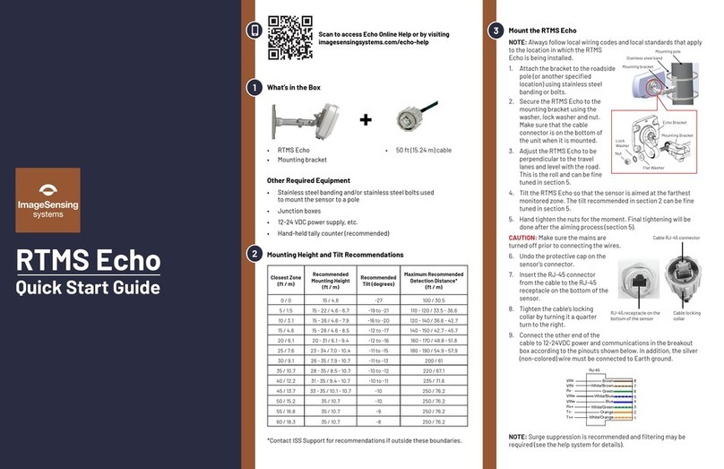
The cable provided by ISS is 50 ft (15.24 m) in length and comes with an 8-pin
RJ-45 connector on the end that connects into the RTMS Echo. The connector
also contains an element to which the ground wire is attached. The other end
of the cable is what needs to be connected to power, communications and
ground in the breakout box. Cable pinout is a combination of standard
Ethernet and custom. The green and orange pair are wired like standard
Ethernet for 100Mbits per second data transfer. The wiring and pinouts for the
connector are shown in the Figure below.
Figure 2-1: RJ-45 Connector Pinouts
The non-colored wire in the cable must be connected to Earth ground in the
breakout box if the cable is not terminated with an RJ-45 connector. If it is
1
2
3
4
5
6
7
8
RJ-45
Green
White/Green
Orange
White/Orange
Blue
White/Blue
White/Brown
Brown
Rx-
Tx-
Rx+
Tx+
VIN+
VIN-
VIN-
VIN+

Chapter 2: Pre-Installation Considerations
RTMS Echo User Guide ©2019 Image Sensing Systems Inc. 2-3
terminated with an RJ-45 connector, the connector must have an element to
which the ground wire can be connected (see examples below).
Figure 2-2: Example RJ-45 External Ground Connectors
Breakout Boxes
The design of an RTMS Echo installation should include a breakout box close
to the RTMS Echo that can be used for setup and maintenance purposes, and
can include surge suppression circuitry and external communications devices
as required. Reference designs are available. The breakout box should be no
more than 50 ft (15.24 m) from the RTMS Echo sensor (see Figure 2-3).
Figure 2-3: Typical Breakout Box Installation
Each breakout box should contain a manufacturers approved surge
suppression package, filters, power supply and communications equipment.

Chapter 2: Pre-Installation Considerations
RTMS Echo User Guide ©2019 Image Sensing Systems Inc. 2-4
Surge Suppression/Filtering
Surge Suppression: The CITEL MJ8-POE-B
has been tested and is the recommended
transient suppressor for RTMS Echo sensors.
Figure 2-4: Citel Surge Suppressor
•
Power over Ethernet surge protector
•
RJ-45 connection for PoE-A or B
•
10/100/1000 Mbps compatible
•
Max DC power:
– 7.5 VDC for pins 1, 2, 3, 6
– 60 VDC for pins 4, 5, 7, 8
•
Max DC current: 1200mA
•
Frequency: 100 MHz
•
Bi-directional protection
•
Shielded enclosure and connectors
•
Din rail mountable
•
UL497B listed
Filtering: The COSEL SNR-10-23-DT line noise
filter has been tested and is the recommended
filter for RTMS Echo sensors.
•
Voltage rating: 50VDC
•
Current rating: 10A
•
Leakage current: 50 uA
•
Capacitance: 0.022 uF
•
Din rail mountable
•
RoHS compliant

Chapter 2: Pre-Installation Considerations
RTMS Echo User Guide ©2019 Image Sensing Systems Inc. 2-5
Connecting Power and Communications
After the RTMS Echo has been mounted to the pole the connections for power
and data communications must be made. For cable pinouts see “Cabling
Considerations” on page 2-2.
A 50 ft (15.24m) Cat 5e cable containing wires for both power and
communications is included with the RTMS Echo sensor. It is strongly
recommended that surge suppression be provided for both power and
communications. In addition, if the power source in the breakout box is solar or
if the source provides power to other equipment in addition to the Echo sensor,
a filter is recommended (see “Surge Suppression/Filtering” on page 2-4).
Figure 2-5 below shows a block diagram of the connections if separate surge
suppressors are used for power and communications. Figure 2-6 shows the
same diagram if a single surge suppressor is used.
Figure 2-5: Separate Surge Suppressors

Chapter 2: Pre-Installation Considerations
RTMS Echo User Guide ©2019 Image Sensing Systems Inc. 2-6
Figure 2-6: Single Surge Suppressor

Chapter 2: Pre-Installation Considerations
RTMS Echo User Guide ©2019 Image Sensing Systems Inc. 2-7
Providing a Proper Ground
Providing a low resistance earth ground connection is essential to achieving
effective surge protection. Total resistance from the protected circuit to the
earth should be <5ohms.
A grounding rod (see Figure 2-7) should be at least 1.83 m (6 ft) in length and
placed as close as possible to the base of the RTMS Echo mounting pole. The
grounding conductor should be flexible copper braid or copper wire 12AWG or
larger.
Figure 2-7: Earth Ground Connection
The earth grounding rod, together with proper ground of the breakout box, and
surge protecting devices installed in close proximity of the mounting pole,
create a barrier or ‘sink hole’ for any charges and surges coming towards the
sensor from the surrounding area (see Figure 2-8). These charges and surges
may be caused by industrial noise, power surges, or lightning.
Grounding conductor
6 foot copper rod

Chapter 2: Pre-Installation Considerations
RTMS Echo User Guide ©2019 Image Sensing Systems Inc. 2-8
Figure 2-8: Surge Channeled into Earth Ground
Thunderstorm lightning is in its own class of destructive forces to sensors.
Typically, it can generate 30 to 300 kA of current, far beyond the capabilities of
any surge protecting devices. Therefore, a direct or near direct lightning hit
may cause equipment damage even in the presence of surge/transient
protecting devices.
Because lightning is a major influence on power line surge, it is important to
understand the exposure to thunderstorms in the area where the RTMS Echo
sensor is being installed. In areas that are exposed to large number of
thunderstorms, protecting sensors will be more challenging.
Power and comm lines
Surge induced into lines Lightning discharge
Earth grounding rod
Mounting pole, sensor
and breakout box

Chapter 2: Pre-Installation Considerations
RTMS Echo User Guide ©2019 Image Sensing Systems Inc. 2-9
Placement in Side-Fired Highway Configuration
RTMS Echo is designed to mount on existing poles and road structures.
Figure 2-9 shows typical cases of RTMS Echo side-fired/highway sites. The
design considerations for each case are:
•
Case 1 — Maximal utilization of the RTMS Echo zone capability.
Limitations are as follows:
– A 12-zone coverage may require a larger setback (the distance to
the first lane) mounting height and/or greater tilt setting (see
“Height, Setback, Tilt Requirements” on page 2-11).
– In almost all cases, the RTMS Echo can resolve the barrier return
signal from that of the vehicles in the lane immediately behind it as
long as 50% of vehicle can be seen (see “Guardrails and Barriers”
on page 2-12).
•
Case 2 — Overpass installations: Do not mount the RTMS Echo on a
perpendicular overpass. Instead, use poles located at least 5 m (17 ft)
from the overpass to avoid multi-path. Multi-path is a situation in which
the reflected signals from vehicles can also reach the RTMS Echo by a
secondary reflection from a large flat surface (such as a sign or
overpass).
•
Case 3 — Using median poles to mount two RTMS Echo sensors, one
per direction may save poles but the designer should verify available
set-back (see “Height, Setback, Tilt Requirements” on page 2-11).
•
Case 4 — Sign-structure installations (see “Installing RTMS Echo on
Sign Structures” on page 2-14).
•
Case 5 — Typical ramp metering site.

Chapter 2: Pre-Installation Considerations
RTMS Echo User Guide ©2019 Image Sensing Systems Inc. 2-10
Figure 2-9: RTMS Echo Side-Fired Highway Sites
2
3
45
2
2
Setback
1
Other manuals for RTMS Echo
1
Table of contents
Other Image Sensing Systems Radar manuals
Popular Radar manuals by other brands

Fortem Technologies
Fortem Technologies TrueView R20 quick start guide

GSSI
GSSI UtilityScan quick start guide

Endress+Hauser
Endress+Hauser Levelflex M FMP45 operating instructions
HIK VISION
HIK VISION DS-TMG033 user manual
Endress+Hauser
Endress+Hauser Micropilot FMR51 technical information

Endress+Hauser
Endress+Hauser Micropilot FMR51 operating instructions
