Bindicator RS-485 User manual

InvisiLink™Wireless Radio
Installation & Operation Manual
IOM
WRL180213 Rev. B


InvisiLinkTM Wireless Radio
Installation & Operation Manual
CONTENTS
I. HANDLING AND STORAGE..................................................................................................................... 1
INSPECTION AND HANDLING
DISPOSAL AND RECYCLING
STORAGE
II. GENERAL SAFETY................................................................................................................................... 2
AUTHORIZED PERSONNEL
USE
MISUSE
III. PRODUCT DESCRIPTION ....................................................................................................................... 3
FUNCTION
FEATURES
TECHNICAL SPECIFICATIONS
IV. MECHANICAL INSTALLATION................................................................................................................. 4
MOUNTING CONSIDERATIONS
DRILLING HOLES IN THE ENCLOSURE
PREPARE THE ENCLOSURE FOR CONDUIT
Figure 1. Bottom View
TO MOUNT THE INVISILINK ENCLOSURE
TO MOUNT THE EXTENDED RANGE ANTENNA
V. ELECTRICAL INSTALLATION .................................................................................................................. 6
GENERAL SAFETY
DISCONNECT REQUIREMENTS FOR PERMANENTLY INSTALLED EQUIPMENT
RS-485/RS-422 EQUIPMENT MATRIX
Figure 2: Wiring Diagram RS-422
Figure 3: Wiring Diagram RS-485 (MODBUS)
Figure 4: Wiring Diagram RS-422 with 4-20 mA Input Box
VI. SET-UP ..................................................................................................................................................... 9
Figure 5: LED Indicator Lights
Figure 6. Point-to-Point
Figure 7. Point-to-Point (Multi Device)
Figure 8. Multi Point
Figure 9. 4-20 mA Point-to-Point
Figure 10: Dip Switches
SAFETY SYMBOLS
WARNING:
IDENTIFIES CONDITIONS OR PROCEDURES, WHICH IF NOT FOLLOWED,
COULD RESULT IN SERIOUS INJURY. RISK OF ELECTRICAL SHOCK.
CAUTION:
IDENTIFIES CONDITIONS OR PROCEDURES, WHICH IF NOT FOLLOWED,
COULD RESULT IN SERIOUS DAMAGE OR FAILURE OF THE EQUIPMENT.
VII. MAINTENANCE ...................................................................................................................................... 12
VIII.TROUBLESHOOTING ............................................................................................................................ 13

1
www.bindicator.com
WRL180213 Rev. B
InvisiLink Wireless Radio
I. HANDLING AND STORAGE
SAVE THESE INSTRUCTIONS
INSPECTION AND HANDLING
Do not dispose of the carton or packing materials.
Each package should be inspected upon receipt for damage that may have occurred due to mishandling during
shipping. If the unit is received damaged, notify the carrier or the factory for instructions. Failure to do so may
void your warranty. If you have any problems or questions, consult Customer Support at 1-800-778-9242.
DISPOSAL AND RECYCLING
This product can be recycled by specialized companies and must not be disposed of in a municipal collection
site. If you do not have the means to dispose of properly, please contact for return and disposal instructions or
options.
STORAGE
If the device is not scheduled for immediate installation following delivery, the following steps should be
observed:
1. Following inspection, repackage the unit into its original packaging.
2. Select a clean dry site, free of vibration, shock and impact hazards.
3. If storage will be extended longer than 30 days, the unit must be stored at temperatures between
-40º and 158º F (-40º to 70° C) in non-condensing atmosphere with humidity less than 85%.
CAUTION: DO NOT STORE A NON-POWERED UNIT OUTDOORS FOR A PROLONGED PERIOD.

2
www.bindicator.com
WRL180213 Rev. B
II. GENERAL SAFETY
AUTHORIZED PERSONNEL
All instructions described in the document must be performed by authorized and qualied service personnel
only. Before installing the unit, please read these instructions and familiarize yourself with the requirements and
functions of the device. The required personal protective equipment must always be worn when servicing this
device.
USE
The device is solely intended for use as described in this manual. Reliable operation is ensured only if the
instrument is used according to the specications described in this document. For safety and warranty reasons,
use of accessory equipment not recommended by the manufacturer or modication of this device is explicitly
forbidden. All servicing of this equipment must be performed by qualied service personnel only. This device
should be mounted in locations where it will not be subject to tampering by unauthorized personnel.
MISUSE
Improper use or installation of this device may cause the following:
• Personal injury or harm
• Application specic hazards such as vessel overll
• Damage to the device or system
If any questions or problems arise during installation of this equipment, please contact Customer Support at
800-778-9242.

3
www.bindicator.com
WRL180213 Rev. B
III. PRODUCT DESCRIPTION
FUNCTION
InvisiLink is a wireless radio solution for devices that communicate via RS-485 or RS-422. A radio is connected
to both the measuring device, like a Yo-Yo or controller, and the receiving device, like an ORB. Then the
InvisiLink radio sends data back and forth between the devices. This system eliminates the need for cables and
conduit connecting a measuring device to a device collecting data. It is also possible to have a single device
receive multiple data streams from ‘send’ devices.
FEATURES
• Distances up to 3,000 ft (914 m)
• RS-485 or RS-422 Connection Capabilities
• NEMA 4X Enclosure
• Standard and Extended Range Antenna Options
• LED Indicator Lights
TECHNICAL SPECIFICATIONS
FUNCTION
Input/Output RS-485 or RS-422
Frequency 900 Mhz
Power Supply 120 VAC +/- 10%; 60Hz
30 watt
Ambient temperature (Electronics)
-40º to 185º F (-40º to +85º C)
PERFORMANCE
Transmission Speed (Baud Rate) RS-485: 115.2
RS-422: 9600
Transmit Power 1 mW to 1 W
Transmission Distance 3,000 ft (914 m)*
PHYSICAL
Housing Material NEMA 4X, Fiberglass
Extended Range Antenna Up to 40 miles (64 km) NEMA 4X Outdoor includes lightening arrestor**, includes 2 ft
(61 cm) connection cable
Visual Indicators LED Lights (Power, Communication and Signal)
*Distances may be reduced depending on environment. Maximum distance determined in indoor/urban environment with direct line of sight,
no obstacles.
** Consult Factory for extended range distances.
4
www.bindicator.com
WRL180213 Rev. B
IV. MECHANICAL INSTALLATION
WARNING: REMOVE POWER FROM THE UNIT BEFORE INSTALLING REMOVING OR MAKING
ADJUSTMENTS.
CAUTION: DO NOT ROUTE SERIAL CABLES IN THE SAME CONDUIT WITH AC POWER CABLES.
CAUTION: THIS DEVICE COMPLIES WITH PART 15 OF THE FCC RULES. OPERATION IS
SUBJECT TO THE FOLLOWING TWO CONDITIONS: (I) THIS DEVICE MAY NOT CAUSE HARMFUL
INTERFERENCE AND (II) THIS DEVICE MUST ACCEPT ANY INTERFERENCE RECEIVED, INCLUDING
INTERFERENCE THAT MAY CAUSE UNDESIRED OPERATION.
MOUNTING CONSIDERATIONS
• Mounting hardware is not supplied by Bindicator.
• When mounting the enclosure ensure there is enough clearance to open the front door completely.
Removal, insertion, and wiring of the modular PCB is done through the front of the unit.
• Preferred direct line of sight between antennas (devices)
• Minimize metallic obstacles between devices
• Should not be close to high voltage sources
WHEN SEALING CONDUIT CONNECTIONS, ONLY USE SIKAFLEX 1A POLYURETHANE SEALANT
OR DOW CORNING RTV 738 OR 739. OTHER SEALANTS MAY CONTAIN ACETIC ACID WHICH IS
HARMFUL TO SENSORS AND ELECTRONICS.
DRILLING HOLES IN THE ENCLOSURE
The standard berglass NEMA 4X rated enclosure has no openings through which to route cables or install the
conduit. Hole location is critical for proper conduit installation. Check clearances to ensure that the ttings and
wire routing will not interfere with the PCB or enclosure door.
DO NOT DRILL HOLES THROUGH THE TOP OF ENCLOSURE AS THIS MAY ALLOW MOISTURE
SEEPAGE, WHICH CAN DAMAGE THE ELECTRONICS AND VOID THE WARRANTY.
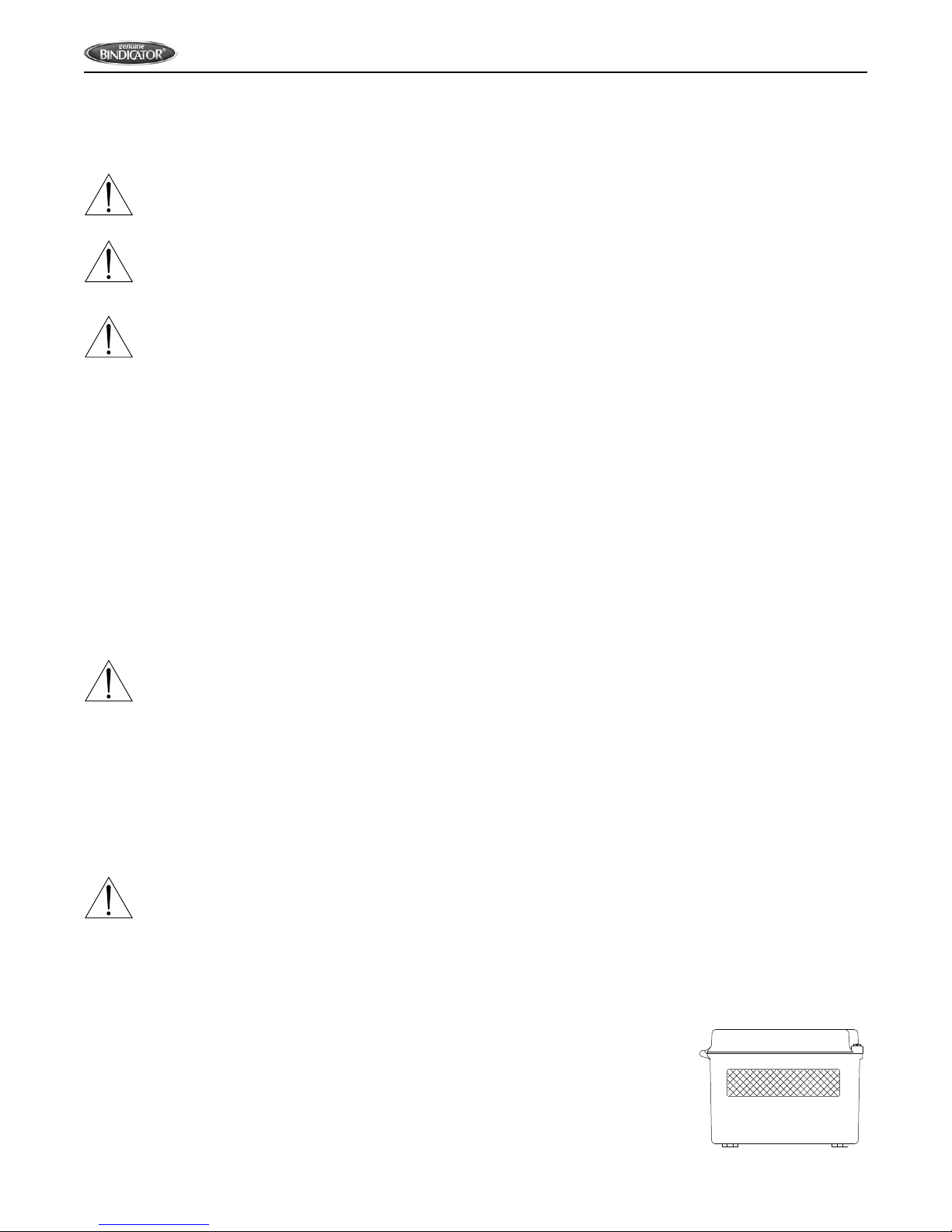
PREPARE THE ENCLOSURE FOR CONDUIT
1. Open door of the enclosure.
2. Remove all four (4) mounting screws that attach the board to the enclosure.
3. Remove entire board, and place in a safe location.
4.
Make a separate hole for the AC cable, the serial and CAT 5 wiring. Holes
should be made in the front 2 inches of the bottom of the enclosure (Figure 1);
this allows for appropriate spacing for cables.
Figure 1. Bottom View

5
www.bindicator.com
WRL180213 Rev. B
5.
Clean enclosure of any debris, replace the board back into the enclosure, using all four (4) mounting screws.
6. Determine desired location for mounting the unit.
TO MOUNT THE INVISILINK ENCLOSURE
1. Hold the enclosure against the wall in the desired location and mark the positions of the mounting holes.
Place the enclosure in a safe location.
2. Drill the mounting holes in the wall.
3. Attach the enclosure to the wall using hardware that will secure it rmly in place.
TO MOUNT THE EXTENDED RANGE ANTENNA
The extended range antenna can either be mounted with the attached plate or with U-bolts, both included as
standard. The cable between the radio and the antenna is 2 ft (61 cm) in length; plan the location of the unit and
antenna accordingly.
If using the plate, pre-drill holes in desired location and bolt to structure.
If using the U-bolts, determine location on pipe or pole to mount the antenna and attach with mounting hardware
.

6
www.bindicator.com
WRL180213 Rev. B
V. ELECTRICAL INSTALLATION
WARNING: REMOVE POWER FROM THE UNIT BEFORE INSTALLING, REMOVING OR MAKING
ADJUSTMENTS
GENERAL SAFETY
When using electrical equipment, you should always follow basic safety precautions, including the following:
• The installation/wiring of this product must comply with all national, federal, state, municipal, and local
codes that apply.
• Properly ground the enclosure to an adequate earth ground.
• Do not modify any factory wiring. Connections should only be made to the terminals described in this
section.
• All connections to the unit must use conductors with an insulation rating of 300 V minimum, rated for
105 C, a minimum ammability rating of VW-1, and be of appropriate gauge for the voltage and current
required (see specs).
• Do not allow moisture to enter the electronics enclosure. Conduit should slope downward from the
housing. Install drip loops and seal conduit with silicone rubber product.
DISCONNECT REQUIREMENTS FOR PERMANENTLY INSTALLED EQUIPMENT
A dedicated disconnecting device (circuit breaker) must be provided for the proper installation of the unit. If
independent circuits are used for power input, individual disconnects are required. Disconnects must meet the
following requirements:
• Located in close proximity to the device
• Easily accessible to the operator
• Appropriately marked as the disconnect for the device and associated circuit
• Sized appropriately to the requirements of the protected circuit (See Specications)
RS-485/RS-422 EQUIPMENT MATRIX
COMMUNICATION
DEVICE RS-485 RS-422
Bindicator 3D Level Scanner x
Bindicator Mark-4/GP-4 Yo-Yo x
Bindicator/Kistler-Morse ORB x x
Bindicator/Kistler-Morse ORB 4-20mA Input Box x
Bindicator SonoTracker x
Kislter-Morse Ultrawave x
Kistler-Morse MVS x
Kistler-Morse STXplus x
Kistler-Morse SVS2000 x
Kistler-Morse Weigh II x
Niagara Meters 5600 Controller x
Note: RS-485 Communication will be programmed at a baud rate of 115200;
RS-422 Commuication will be programmed at a baud rate of 9600.

7
www.bindicator.com
WRL180213 Rev. B
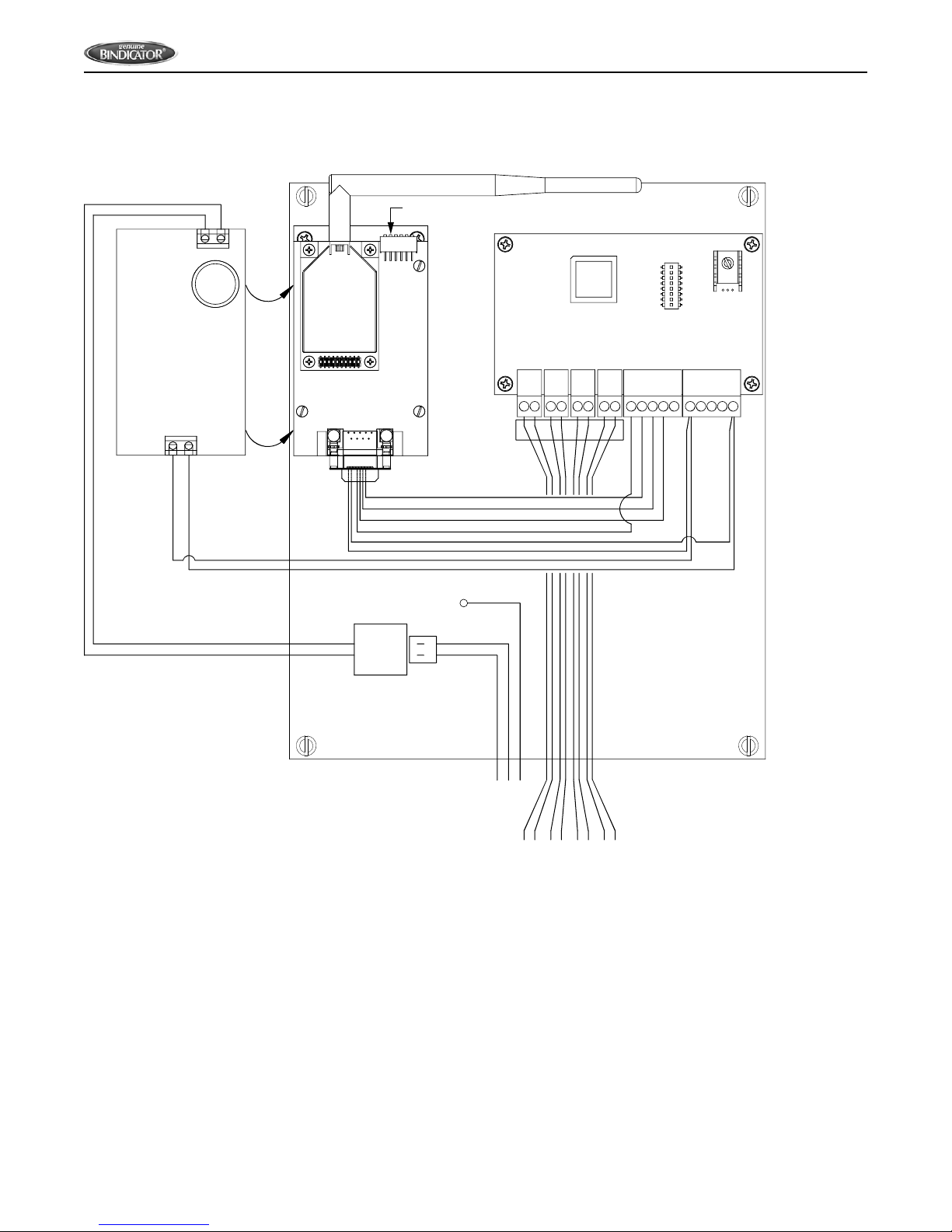
Figure 2: Wiring Diagram RS-422
8 POS CONN.
WIRING DIAGRAM RS-422
5 14 3 2
9 8 7 6
-
5
+
9
Pin 5 - Orange
Pin 9 - Blue
Pin 2 - Gray
Pin 7 - Brown
Pin 8 - Green
N
L
CUSTOMER WIRING
GND
RS-422
N
L
COM-
COM+
OUT- / Tx-
OUT+ / Tx+
IN- / Rx-
IN+ / Rx+
PWR
RS-485
RS-422
OUT- / Tx-
OUT+ / Tx+
IN- / Rx-
IN+ / Rx+
GND
N
L
WIRELESS BOARD
Figure 6.
POWER BOARD
Pin 3 - Yellow
OUT- / Tx-
OUT+ / Tx+
IN- / Rx-
IN+ / Rx+
Instrument
Figure 3: Wiring Diagram RS-485 (MODBUS)
8 POS CONN.
WIRING DIAGRAM RS-485 (MODBUS)
5 14 3 2
9 8 7 6
Pin 2 - Gray
Pin 8 - Green
GND
COM-
COM+
GND
N
L
RS-485
N
L
COM-
COM+
OUT- / Tx-
OUT+ / Tx+
IN- / Rx-
IN+ / Rx+
PWR
RS-485
RS-422
WIRELESS BOARD
-
5
+
9
N
L
POWER BOARD
Pin 5 - Orange
Pin 9 - Blue
COM+
COM-
Figure 6.
CUSTOMER WIRING
Instrument
8
www.bindicator.com
WRL180213 Rev. B
Figure 4: Wiring Diagram RS-422 with 4-20 mA Input Box
2 POS
CONN.
WIRING DIAGRAM RS-422 W/4-20
5 14 3 2
9 8 7 6
Pin 5 - Orange
Pin 9 - Blue
N
L
PWR
CUSTOMER
WIRING
GND
N
L
GND
This Power Board
is mounted under the
Wireless Board to the right.
The (2) boards are shown
side-by-side for clarity.
-
+
IN+
IN-
OUT+
OUT-
Pin 2 - Gray
Pin 3 - Yellow
Pin 7 - Brown
Pin 8 - Green
+
-
+
-
+
-
+
-
Ch. 1Ch. 2Ch. 3Ch. 4
+
-
+
-
+
-
+
-
Ch. 1Ch. 2Ch. 3Ch. 4
4-20mA
N
L
-+
Figure 6.
9
www.bindicator.com
WRL180213 Rev. B
VI. SET-UP
1. The enclosure has been mounted.
2. Determine Point to Point or Multi-Point conguration. See Figure 10 for Dip Switch settings.
3. Serial cable has been wired, and power has been wired and turned on.
4. Ensure the Power Indicator LED light is solid red and that Serial Data In/Out LEDs are ashing. See
Figure 5.
No additional programming is required. All radio enclosures should automatically begin sending and receiving signals.
NOTE: Communication device types cannot be mixed. RS-485 devices must be connected to another RS-485
device; it will not receive signals to or from a RS-422 device.
To ensure unit is functioning properly, check the LED indicator lights.
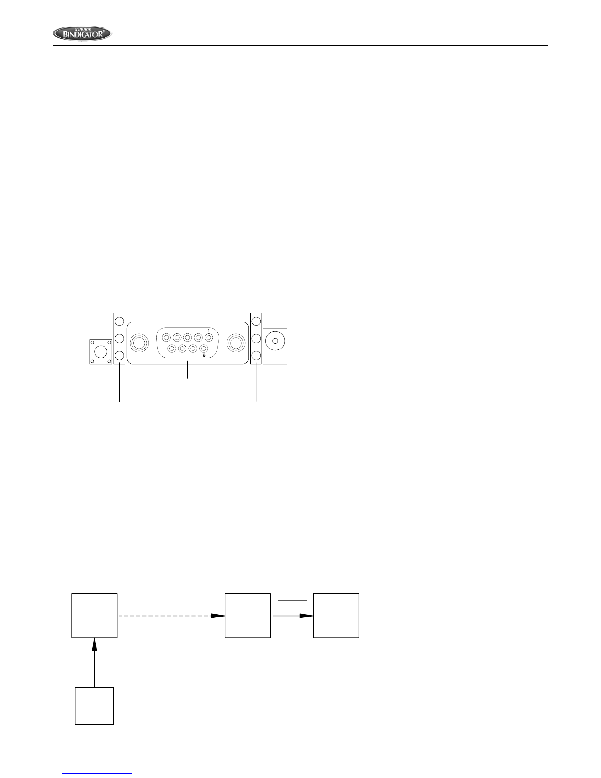
Figure 5: LED Indicator Lights
Indicator LEDs
Yellow (top) = Serial Data Out (to host)
Green (middle) = Serial Data In (from host)
Red (bottom) = Power/TX Indicator (Red light
is on when powered; it pulses on/off briefly
during RF transmissions
DB-9 Serial Port
RSSI LEDs - Strength of signal
3 LEDs ON = Very Strong Signal
2 LEDs ON = Strong Signal
1 LED ON = Moderate Signal
0 LED ON = Weak Signal
LED Layout and Indications DB-9
If indicator lights are not working, please proceed to the Troubleshooting section of this manual for assistance.
Notes (Used for Figures 6-9):
1. All remote devices must use the same protocol.
2. If device protocol = RS485, then InvisiLink Base must be RS485.
If Device Protocol = RS422 or 4-20 mA, then InvisiLink Base must be RS422.
Figure 6. Point-to-Point
InvisiLink
Remote
InvisiLink
Base
ORB
or
PLC
Device
RS485
RS422
RS485
RS422
Note 1
Note 2
10
www.bindicator.com
WRL180213 Rev. B
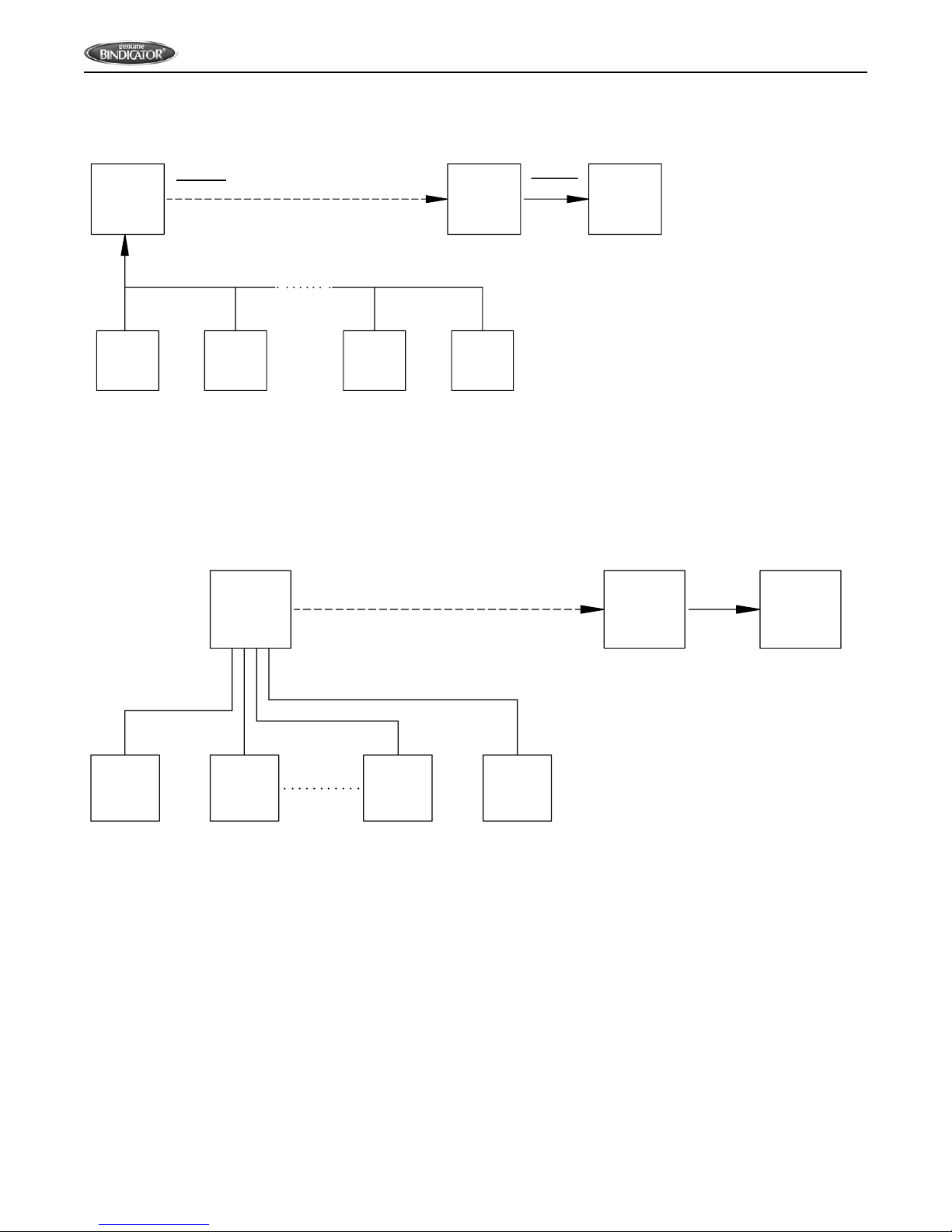
Figure 7. Point-to-Point (Multi Device)
InvisiLink
Remote
InvisiLink
Base
ORB
or
PLC
Device
1
Device
2
Device
N-1
Device
N
N= Number of Devices
= 10 for RS422
= 32 for RS485
RS485
RS422
Note 1
Note 2
RS485
RS422
Figure 8. 4-20 mA Point-to-Point
InvisiLink InvisiLink
ORB
4-20mA Base
N = Max of 16 Devices
ORB
or
PLC
Device
1
Device
2
Device
N-1
Device
N
RS422RS422
4-20mA
CHANGING POINT-TO-POINT TO MULTI-POINT
1. Determine the multipoint base, should be the device connected to the PCL or ORB, change Dip
Switches 5 and 6 to the OFF position.
2. All other units will be considered multipoint remote units; change Dip Switch 5 to OFF and Dip Switch 6
to ON.
3. Serial cable should be wired, and power has also been wired and turned on.
4. Ensure the Power Indicator LED light is solid red and that Serial Data In/Out LEDs are ashing. See
Figure 5.
11
www.bindicator.com
WRL180213 Rev. B
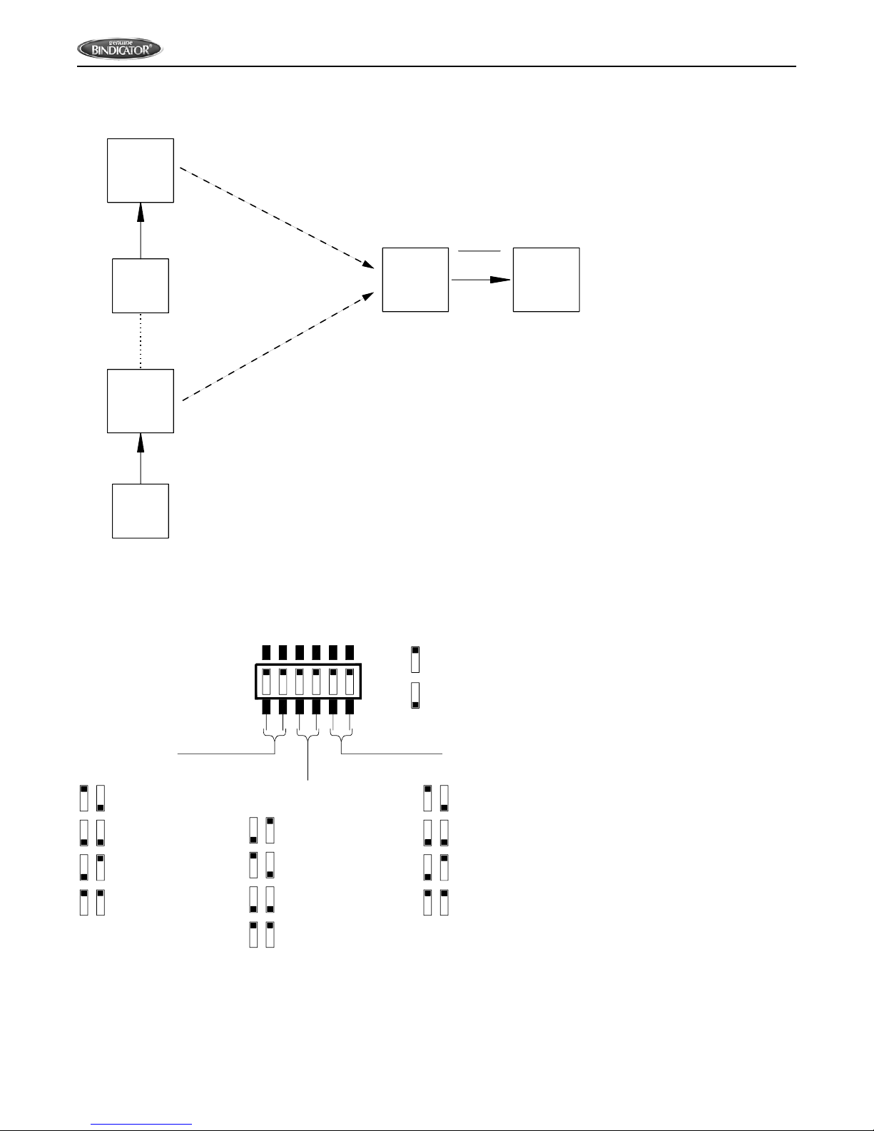
Figure 9. Multi Point
InvisiLink
Remote
Device
RS485
RS422
Note 1.
InvisiLink
Remote Multi-Point Remote
Multi-Point Remote
(N)
Device
RS485
RS422
Note 1.
InvisiLink ORB
or
PLC
RS485
RS422
Note 2.
(N) = Max of 50 Devices.
Each remote must be identical and
match the base protocol.
Multi-Point Base
To set multi-point units, see gure 10 for dip switch settings.
Figure 10: Dip Switches
Serial Interface
Switches 1 & 2
RS-485/422 Termination
Switches 3 & 4
TX/RX Mode
Switches 5 & 6
1 2 3 4 5 6
= 2-wire RS-485
= Not used
= Factory Reserved
= 4-wire RS-422
= Multipoint-Base
= Point-to-Point
= Factory Reserved
= Multipoint-Remote
= 2-wire RS-485
Termination
= Factory Reserved
= Factory Reserved
1 2
3 4
5 6
= None
= ON (up)
= OFF (down)
NOTE: Point to point is used when one radio is talking to one radio only; multi-point is used when there are
multiple remotes and/or bases.

12
www.bindicator.com
WRL180213 Rev. B
VII. MAINTENANCE
PREVENTATIVE MAINTENANCE
See ORB 4-20mA Input Box IOM for specic maintenance and possible replacement parts for the ORB 4-20mA
Input Box unit. There is no preventative maintenance for a single unit radio.
REPLACEMENT PARTS
LUC044016 Extended Range Antenna, 2 ft (61 cm) Connection Cable
LUC044023 Extended Range Antenna, 10 ft (3 m) Connection Cable
LUC044005 Extended Range Antenna Lightening Arrestor
13
www.bindicator.com
WRL180213 Rev. B
VIII. TROUBLESHOOTING
For technical or service questions, please call the manufacturer Customer Support at 1-800-788-9242.
For detailed dimensional drawings, go to www.bindicator.com
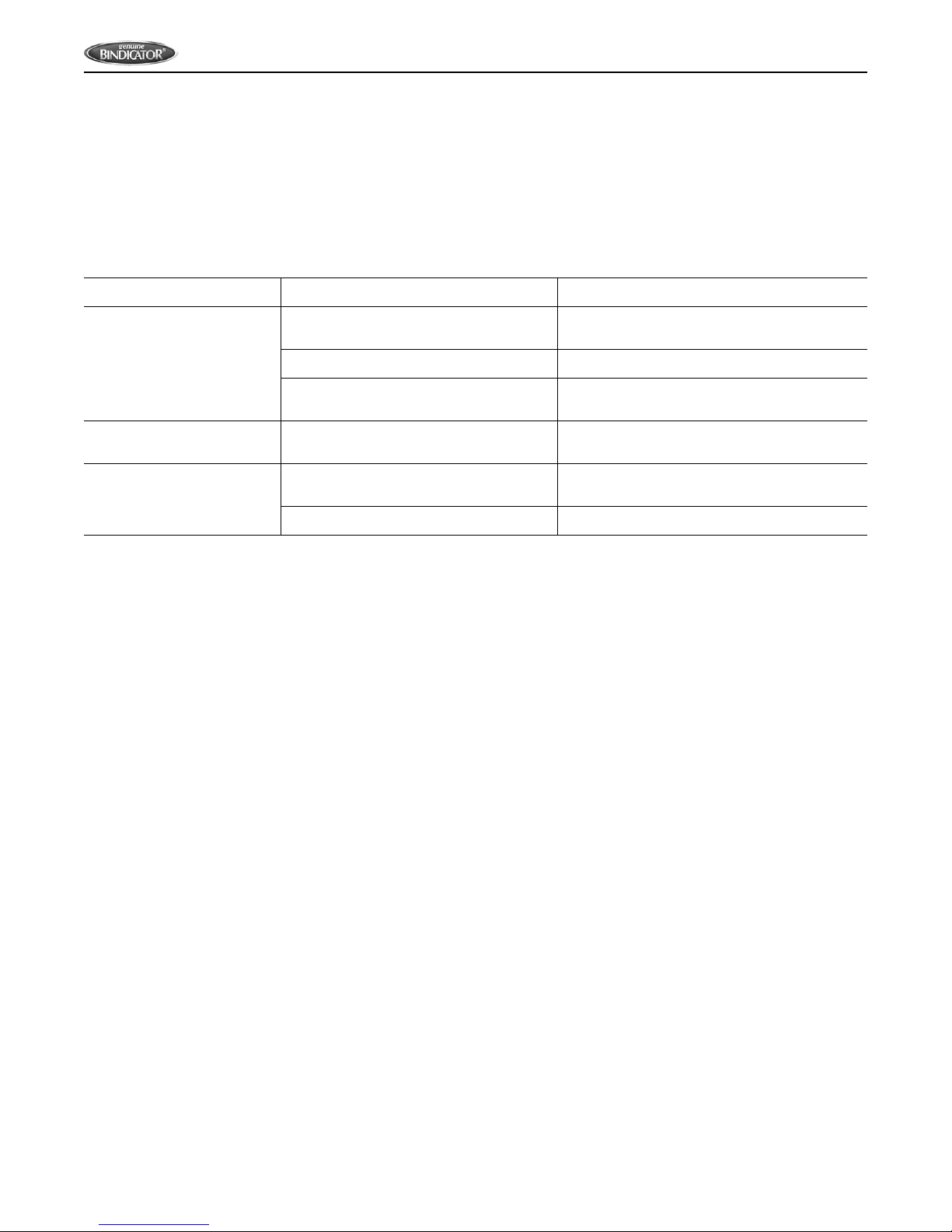
SYMPTOM POSSIBLE CAUSE CORRECTIVE ACTION
RSSI LEDs not on
Radio(s) are not powered on Make sure the Indicator LED is red; if not
check wiring
Protocol switches do not match Check dip switches and change if needed
Antenna not connected Tighten antenna and put in most direct line
of sight to other radio
Red Indicator LED is not
on Not wired correctly Reference wiring diagrams and check
wiring
Top and or middle
Indicator LEDs is not
ashing
Both (all) radios may not be powered
on Make sure the Indicator LED is red; if not
check wiring on both (all) units.
Units are not communicating Check all wiring

14
www.bindicator.com
WRL180213 Rev. B
NOTES

15
www.bindicator.com
WRL180213 Rev. B
NOTES

150 Venture Boulevard
Spartanburg, SC 29306
Tel: (800) 778-9242
Fax: (864) 574-8063
sales@bindicator.com
www.bindicator.com
2014 All rights reserved.
All data subject to change without notice.
WRL180213 Rev. B
This manual suits for next models
2
Table of contents


