Ritron RPM 60 Series User manual
RPM 60 SERIES FM MOBILE RADIO
OWNER'S MANUAL
VHF RPM-160
UHF RPM-460

page ii
DESCRIPTION PAGE
ACCESSORIES
Optional Accessories .................................................................. ii
FCC LICENSE REQUIRED .................................................................. 1
FCC Regulations .......................................................................... 1
Service ....................................................................................... 1
How to Obtain an FCC Radio License .......................................... 1
INTRODUCTION ................................................................................. 2
General ....................................................................................... 2
nspection .................................................................................... 2
Model dentification ...................................................................... 2
CAUTIONS ........................................................................................ 2
OWNER INFORMATION ..................................................................... 3
STANDARD FEATURES ...................................................................... 4
RADIO CONTROLS - GENERAL ........................................................ 5
RADIO OPERATION ........................................................................... 8
LIMITED WARRANTY ................................................... BAC COVER
FIGURES:
1. Model dentification .................................................................. 2
2. Operating Controls .................................................................. 5
3. Microphone nstallation ............................................................ 6
4. External Connections ............................................................... 7
TABLE OF CONTENTS ACCESSORIES
OPTIONAL ACCESSORIES:
RM-6TT Hand Microphone with 12-button Touch Tone
Keypad
RM-4 Replacement Hand Microphone
RM-6 Desktop microphone
RSP-5 External Speaker with 10 ft. cord, 3.5 mm plug
RAM-1545 Dual-Band (VHF/UHF) magnet-mount antenna
with 20 ft RG-58 coaxial, BNC connector
(requires BNC to UHF adaptor)
RAM-45 UHF 1/4 wave whip antenna with 12 ft RG-58
coaxial, PL-259 connector
RPM -12 Replacement nstallation Kit for RPM radio,
ncludes:
Mobile radio mounting bracket
12 VDC power cable with in-line fuse
Microphone hang-up bracket
Hardware and installation instructions
RPM-60ACC Accessory Connector Cable
GGT-1F DTMF Decoder & Relay Control Board
RPM-MRM-e RPM-160/460 Maintenance/Repair/Operating
Manual (CD-ROM)

page 1
FCC REGULATIONS
LICENSING
The FCC requires the owners of the radios to obtain a station license before using them.
The station licensee is responsible for ensuring that transmitter power, frequency and
deviation are within the limits specified by the station license. The station licensee is also
responsible for proper operation and maintenance of the radio equipment. This includes
checking the transmitter frequency and deviation periodically, using appropriate methods.
To get a FCC license for V F or U F frequencies, submit FCC application Form 000600
& Form 159 as indicated in the block at right. Your Ritron dealer can help you with this
process.
SAFETY STANDARDS
The FCC (with its action in General Docket 79-144, March 13, 1985) has adopted a safety
standard for human exposure to radio frequency electromagnetic energy emitted by FCC
regulated equipment.
Ritron observes these guidelines and recommends that you do so also:
·DO NOT operate a mobile radio transmitter when someone outside the vehicle is within two feet of the
antenna.
·DO NOT transmit with a fixed radio(base station, microwave, rural telephone RF e uipment) or
marine radio when someone is within two feet of the antenna.
·DO NOT operate any radio transmitter unless all RF connectors are secure and any open connectors
are properly terminated.
·DO NOT operate radio e uipment near electrical blasting caps or in an explosive atmosphere.
·GROUND ALL RADIO EQUIPMENT according to RITRONs installation sheet.
·RITRON products should be repaired only by RITRON authorized personnel.
SERVICE
Federal law prohibits you from making any internal adjustments to the transmitter, and/ or
from changing transmit frequencies unless you are specifically designated by the lic-
ensee. If your radio equipment fails to operate properly, or you wish to have the radio
programmed, contact your authorized dealer or Ritron.
FCC LICENSE REQUIRED
HOW TO OBTAIN AN FCC RADIO LICENSE
Federal Communications Commission
(FCC) Licensing Information
Because your Ritron radio operates on Private Land
Mobile frequencies, it is subject to the Rules and
Regulations of the FCC, which requires all operators
of these frequencies to obtain a station license before
operating their equipment. Make application for your
FCC license on FCC Forms 600 and 159.
To have forms and instructions faxed to you by
the FCC, call the FCC Fax-On-Demand system at
202-418-0177
from your fax machine;
request Document 000600 & Form 59.
To have Document 000600 & Form 59 mailed to you,
call the FCC Forms Hotline at
800-418-FORM (800-418-3676)
For help with questions concerning the
license application, contact the FCC at
888-CALL-FCC (888-225-5322)
You must decide which radio frequency(ies) you
can operate on before filling out your application.
For help, call Ritron at
800-USA-1-USA (800-872-1872)
page 2
GENERAL
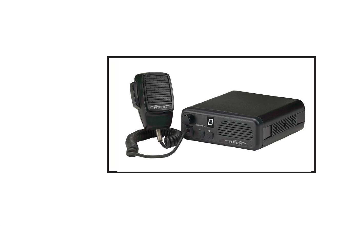
The Ritron RPM 60 Series Mobile is a
programmable two-way radio that can transmit
and receive on any one of 35 channels in the
professional FM communications band (V F
or U F band). This radio features (2)
programmable front panel buttons and a single
digit alpha-numeric LED display. Each channel
can be programmed to contain a unique set of
operating frequencies and options. These
options include industry standard signaling
formats: Quiet Call, Digital Quiet Call, Selcall
(3 to 7 Tone), DTMF and 2-Tone Sequential.
Since the Ritron RPM 60 Series Mobile transmits
on communications frequencies authorized by
the Federal Communications Commission
(FCC), you must license your radios before use.
See " OW TO OBTAIN A FCC RADIO LICENSE"
section on the preceeding page.
INTRODUCTION
OPERATING PRECAUTIONS
TAKE PRECAUTIONS IN THE FOLLOWING
ENVIRONMENTS TO MAXIMIZE THE LIFE OF
YOUR ELECTRONIC RADIO EQUIPMENT.
MOISTURE:
The Ritron 60 Series mobiles are not waterproo . DO
NOT immerse or expose to rain.
EXTREME HEAT:
Like all electronic equipment, this mobile should not
be subjected to extreme heat; such as, being
exposed to direct sunlight in a closed vehicle.
VIBRATIONS/SHOCKS:
Although your Ritron 60 Series mobile is designed to
be rugged, it should not be expected to survive
abuse. Avoid dropping the radio.
CHEMICALS:
Detergents, alcohol, aersol sprays, and/or
petroleum products may damage the ront panel
and/or case. Clean the mobiles exterior using a so t
cloth moistened with water.
INSPECTION
The radio package includes a:
Ritron Mobile Radio
RM-4 and Microphone
RPMK-12 Installation Kit
Users Manual
Examine all of the equipment immediately after
delivery and report any damages to the shipping
company.
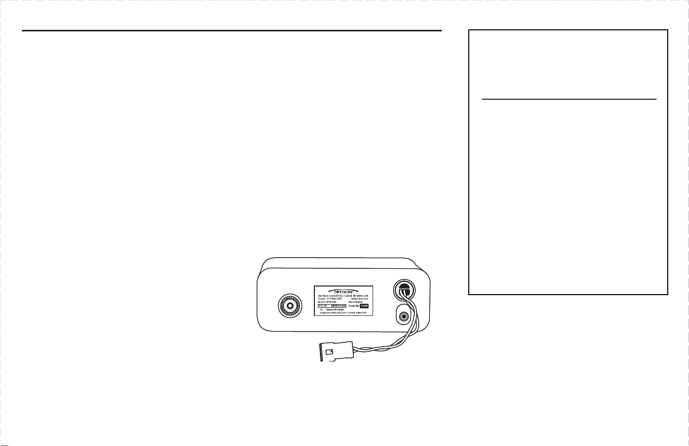
MODEL IDENTIFICATION
The label attached to the back of the mobile
includes both the FCC and Canadian
identification numbers, radio serial number,
radio model number, and operating frequency
range. Ritrons address, telephone number, and
website are also included on this label.
CAUTIONS
- ALL RADIOS -

page 3
RF EXPOSURE
The Ritron RPM 60 Series has been evaluated for
compliance with the maximum exposure limits
for RF energy at the maximum power rating of the
unit with a common unity gain quarterwave
magnetic mount mobile antenna. To ensure
compliance with the Occupational/Controlled
maximum exposure limits, please observe the
following:
When the quarterwave remote magnetic mount
antenna is used, mount the antenna in a location
that will ensure that all persons will be at least
12 inches (30 cm) away from the antenna.
Antennas other than a quarterwave magnetic
mount antenna must be tested with the Ritron
RPM 60 Series Mobile for RF exposure
compliance in the environment in which it is to be
used per the FCCs OET Bulletin 65, Edition
97-01 or Industry Canada RSS-102.
OWNER INFORMATION
SAFETY PRECAUTIONS
RADIO MOUNTING LOCATION
Consider driver and passenger safety when you
choose a location for the radio. Do not mount the
unit overhead or on a sidewall unless you take
special precautions, such as securing the radio
with a safety strap.
Improper installation increases the possibility
that a car accident could dislodge the radio and
make it a dangerous projectile.
VEHICLE OPERATION
•ELECTRONIC SYSTEMS
Check the vehicles manual for any possible
warnings about operating a two-way radio in
a vehicle equipped with an electronic ignition
or anti-lock braking system (ABS) .
•LIQUEFIED PETROLEUM (LP) GAS
FUEL SYSTEM
Radio installation in a vehicle fueled by liquefied
petroleum (LP)gas (with the LP gas container
stored in a sealed-off space, such as a trunk)
must conform to NFPA (National Fire Protection
Association) standard 58.
•AUTOMOBILE BATTERY POWER
Avoid leaving the radio turned on for long periods
when the engine is off, as this could run down the
vehicles battery.

page 4
STANDARD FEATURES
•Last Active Channel Tone
•Resume Scan Tone
•Channel Monitor Lock-out
•Busy Channel Transmit Inhibit
•Reduced Transmit Power
•Transmit Time-Out Timer
•Transmit Clear-To-Talk Tone
•Receive Courtesy Tone
•CTCSS/DCS Encode/Decode Per Channel
•2-Tone Encode/Decode (300-3000 z) Per Channel
•DTMF Encode Using P1/P2/PTT Per Channel
•3 to 7 Tone Encode Using P1/P2/PTT Per Channel
•Channel Scan, Normal & Priority
•Companding Per Channel
•Scrambling Per Channel (not compatible with SLX Scrambler)
Standard Accessories:
•and Microphone, ang-up Clip & ardware
•Mobile Mounting Bracket & ardware
•DC Power Cable & In-line Fuse
Optional Accessories:
•RPM-60ACC Accessory Connector Cable
•RQE-2 MDC-1200 ANI Board
•GGT-1F DTMF Decoder & Relay Control Board
•PC Programmable (Dealer Only)
•Field Programmable
•35 Channels (1-9, A-Z)
•30 Watts RF Power Output
•igh Sensitivity Receiver
•Wideband/Narrowband (25 k z or 12.5 k z) Operation
•Rugged Aluminum Uni-body Construction
•Small, Compact Size: 2.1" x 5.8" W x 6.3" L, 2 lbs. 4 oz.
•Loud 5 Watt Front Firing Speaker
•External Speaker Jack For Remote Mounted Speaker (RSP-5)
•Large Easy-to-read Alpha-numeric Display (1-9, A-Z)
•Dual-color Transmit/Busy Indicator
•Rotary On/Off Volume Control
•2 Dual-function Programmable Function Buttons (PFB)
- Channel Up
- Channel Down
- On- ook Monitor
- Scan On/Off
- Send Call Tone
- Send 2-Tone Sequential
- Send 3 to 7 Tone (Selcall)
- Send DTMF ANI
- Send Emergency Call
- Talk-around
- Nuisance Channel Delete
- igh/Low Transmit Power
- NOAA Weather Scan (V F RPM-160 Only)
page 5
ON/OFF VOLUME CONTROL
The On/Off volume control knob switches the radio on and off, and adjusts the
volume level. To switch the radio on, rotate the control knob clockwise. To
raise the volume level continue rotating the control clockwise.
To lower the volume level, rotate the control counter-clockwise. To switch the
radio off, completely rotate the control counter-clockwise past the click
position.
CHANNEL DISPLAY
The single character Alpha-numeric display indicates the current channel
the radio is operating.
PROGRAMMABLE FUNCTION BUTTONS (P1 & P2)
Each of the two (2) front panel Programmable Function Buttons (PFB)
P1 & P2 can be assigned up to two (2) functions by your dealer. Refer to the
list on page 4.
Note: A function is performed with either a sh rt press or a l ng press of the
Programmable Function Buttons.
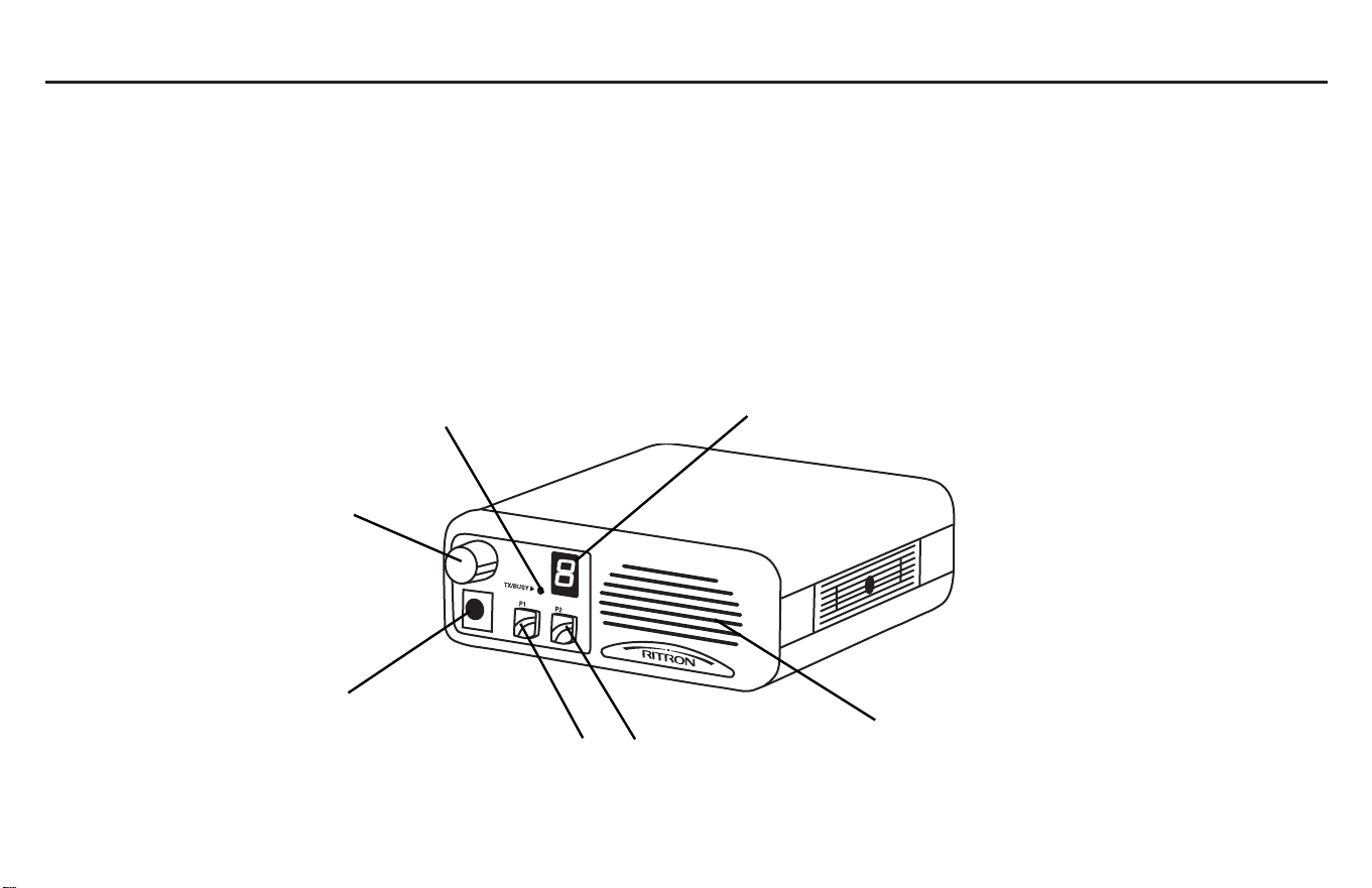
RADIO CONTROLS - GENERAL
On/Off Volume
Control
Transmit [RED]/
Busy [GREEN] Indicator
lpha-numeric
Channel Display
Front Firing
Speaker
Microphone Jack
P1 & P2
Programmable Function
Buttons [PFB]

page 6
TRANSMIT/BUSY INDICATOR
The transmit/busy indicator is a dual color LED. When the operating channel
is busy, the TX/Busy LED will flash GREEN. At any time when the radio is
transmitting, the TX/Busy LED will light RED continuously.
FRONT FIRING SPEAKER
An internal 5 watt speaker is mounted behind the front panel for clear, crisp
audio. An external speaker (RSP-5) may be plugged into the rear panel jack,
which disconnects audio to the front speaker.
MICROPHONE PTT
Pressing the microphone PTT button on the side of the microphone activates
the radios transmitter. While pressing the PTT button, talk directly into the
front of the microphone.
MICROPHONE JACK
The microphone is connected to the front of the radio via a modular plug. The
cord may be removed by pressing up on the underside of the rubber cover
to unseat the plugs lock-tab. The rubber cover is attached to the cord and
should not be removed.
MICROPHONE HANG UP
The microphone hang-up controls squelch and monitor functions through
a hook-switch circuit inside the microphone. The microphone is off-hook
(monitor/carrier squelch) when it is out of the hang-up clip. The microphone
is on-hook (tone squelch, if programmed with QC/DQC tone) when it is in
the hang-up clip.
RADIO CONTROLS - GENERAL (CONTINUED)
Microphone PTT
page 7
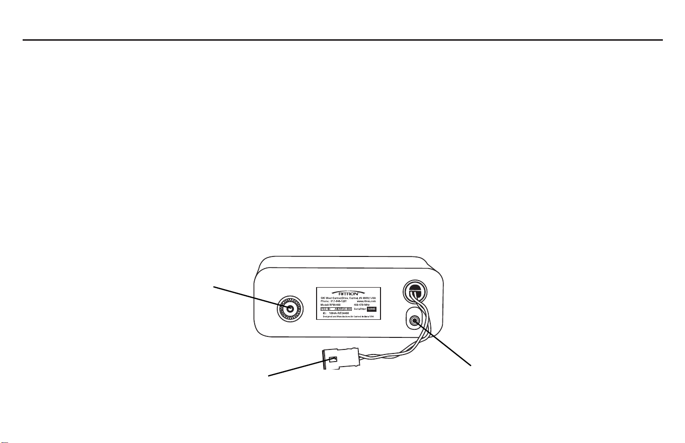
ANTENNA CONNECTOR
The antenna connector is located on the back of the radio. It is a 50 ohm
SO-239 U F Type connector. The radio is capable of 30 watts minimum of
RF power.
EXTERNAL SPEAKER JACK
The external speaker jack is also located on the back of the radio. The
connector is a 3.5mm stereo type connector. Order Ritron #RSP-5 Remote
Mount Speaker. The connections to the speaker are made from the tip and
sleeve of the connector. The internal audio amplifier is capable of supplying
5 Watts of audio power to a 4 ohm speaker.
EXTERNAL DC POWER CONNECTOR
The Ritron RPM 60 Series Mobile is powered from the back of the radio
through a 2-pin connector. The power source must be capable of delivering
10 Amps @ 11-16VDC.
ACCESSORY CONNECTIONS
•The internal accessory connector and optional accessory cable
(order Ritron #RPM-60ACC) allows connection of external
equipment to your radio. External equipment includes: mobile
data terminals, GPS receivers/modems, AVL devices, and/or
Ritron GGT-1 DTMF decoder/relay control board. See your Ritron
dealer for details.
•A second set of internal connections are available for optional
tone signaling encoders/decoders such as MDC-1200 or G-Star
format DTMF ANI boards (order Ritron # RCIM-1000). See your
Ritron dealer for details.
RADIO CONTROLS - GENERAL (CONTINUED)
SO-239 Antenna
Connector
3.5 mm External Speaker Jack/
PC Programming Connection
External 12 DC
Power Connector

page 8
WHAT THE RADIO TONES MEAN
The Ritron RPM 60 Series Mobile responds to certain instructions by sounding a tone or series of tones. These tones can tell you whether the radio is
working as you expect.
OPERATION
Power On: Single high frequency tone when the radio is turned on.
Programmable Buttons: Single high frequency tone when the button is pressed.
Receive Courtesy Beep: Single high frequency tone at the end of a received call to let the user know when to reply.
Transmit Clear to Talk: Single high frequency tone after the PTT is pressed to let the user know when to begin speaking.
Busy Channel Lockout: A repeating single low frequency tone when the PTT is pressed while the channel is busy.
Transmit Time-Out: A repeating single low frequency tone after the PTT has been pressed longer than the trans it ti e-out ti e period.
2-Tone ecode: A fast alternating high and low frequency tone when the radio has decoded a valid 2-tone signal.
Start/Resume Scan: A single low frequency tone when the radio begins/resu es the channel scan function.
Last Active Channel: A single low frequency tone to alert the user what channel was last received during the channel scan.
Priority Scan Channel: A single high frequency tone during the channel scan to alert the user the Priority channel has been received.
Out-Of-Lock: A slow alternating high and low frequency tone to alert the user the radio synthesizer is not operating correctly.
Low Battery: A short high frequency tone every 20 seconds to alert the user that the supply voltage to the radio has dropped below the ini u
usable voltage.
Channel 1 Marker Tone: When incre enting or decre enting the channels, a long, high frequency tone to alert the user that the radio display
is at Channel 1.
Monitor/Squelch: If one of the progra able buttons is progra ed for MONITOR and a channel is progra ed for carrier, tone, or 2-Tone, when
the Monitor button is pressed a single, double, or triple high frequency tone will be heard.
- single tone = Tone Squelch
- double tone = Carrier Squelch
- triple tone = 2-Tone Squelch

page 9
CHANNEL SELECTION
The Ritron RPM 60 Series Mobile provides 35 channels, each of which may
be dealer programmed. The first nine channels appear on the display as
1 through 9, and subsequent channels are displayed as A through Z (with
b and d displayed as lower case letters).
To scroll forward or backward through the channels press the assigned
Programming Function Button (PFB). Any time the display scrolls to Channel
1, a long tone is emitted to let you know you have reached Channel 1
(Channel 1 Marker Tone). This allows you to change channels without
looking at the display.
Note: If a PFB is assigned a long press to perform Channel Up or Channel
Down function:
Press and HOLD the PFB to automatically scroll through all
programmed channels
Release the PFB to stop on the desired channel
OPERATING MODES
You can hear calls with the RPM mobile in receive mode, and broadcast
your voice with the RPM mobile in transmit mode.
RECEIVE:
The RPM mobile can receive broadcasts while the microphone PTT button
is not being pressed. Whether you hear these broadcasts depends upon
the volume and squelch settings.
VOLUME:
You can set the volume by one of t o ays.
1. Press and release the programmable buttons while adjusting
the volume control, using the tones as a reference.
2. When a received broadcast is heard, adjust the volume control
to a desired level.
OPERATION (CONTINUED)
SQUELCH:
Squelch mutes the speaker so that interference from licensees outside of
your group or background noise does not bother the user. There are three
(3) types of squelch in the RPM mobile. The first is carrier squelch that mutes
the speaker if no on-channel transmissions strong enough for the radio to
detect are present. The second is Quiet Call (coded) squelch. This mutes the
speaker unless the radio detects an incoming signal that carries the same
Quiet Call (QC) code as programmed for the selected channel. The third is
2-Tone decode. This mutes the speaker unless the radio detects an
incoming signal that carries the same 2-Tone code as programmed for the
selected channel.
When you remove the microphone from the hang-up clip, Quiet Call squelch
and 2-Tone decode are disabled and the radio reverts to carrier squelch,
allowing all on-channel transmissions strong enough for the radio to detect
to be heard. (This is true, unless the radio is programmed for Channel Monitor
Lock-Out)
MONITOR:
Monitoring lets you hear all on-channel transmissions that are strong
enough for the radio to detect.
Monitoring a C annel Programmed wit Quiet Call (Coded Squelch)
If the channel is programmed with Quiet Call coded squelch, you can
monitor the channel one of two ways.
1. Remove the microphone from the hang-up clip, or;
2. Press and release the PFB assigned to the Monitor function.
The Monitor button may be programmed one of two ways; (see your
dealer for programming)
1. Toggle - In toggle mode, when the PFB is pressed and released,
the radio is switched between coded squelch and carrier squelch.
1 beep means oded s uelch
2 beeps means arrier s uelch

page 10
2. Momentary In momentary mode, when the PFB is pressed and
held, the radio is switched to open squelch. When the button is
released, the radio reverts back to coded squelch. You will hear
1 beep when the button is pressed.
Monitoring a C annel Programmed wit 2-Tone Decode
If the channel is programmed with 2-Tone decode, you can monitor the
channel one of two ways.
1. Remove the microphone from the hang-up clip, or;
2. Press and release the front panel button that is programmed for
the Monitor function.
The PFB button assigned the Monitor function may be programmed one of
two ways; (see your dealer for programming)
1. Toggle - In toggle mode, when the PFB is pressed and released,
the radio is switched between 2-Tone decode, coded squelch and
carrier squelch.
2. Momentary In momentary mode, when the PFB is pressed and
held, the radio is switched to carrier squelch. When the button is
released, the radio reverts back to coded squelch. Also, you will only
hear two beeps when the button is pressed then one beep when the
button is released. To revert to 2-Tone decode, turn the radio off then
back on.
Receiving a 2-Tone Page
To receive a 2-Tone page, select the channel programmed for 2-Tone
decode. When the correct 2-Tone signal is received, the RPM mobile will
generate a ringing tone and a C will be displayed in the LED display to
indicate that a call was received. At this time the radio is in either tone squelch
(if programmed with QC or DQC) or carrier squelch. To reply, remove the
microphone from the hang-up clip and begin speaking into the microphone
while pressing and holding the PTT button. When you are finished
transmitting, place the microphone into the hang-up clip. If there is no activity
for 16 seconds, the radio will automatically reset (if Auto Reset is enabled)
to 2-Tone decode and alert you with a single beep. If you do not respond within
16 seconds after the decode ringing tone, the radio will automatically reset
(if Auto Reset is enabled) to 2-Tone decode and generate a single beep.
If Auto Reset is not programmed, you can reset to 2-Tone decode mode
by:
1. Turning the radio off then back on.
2. If one of the front panel buttons is programmed for Monitor/
Toggle, press and release the button until you hear three beeps.
SCAN:
Scanning allows you to continually check for transmissions on multiple
channels without manually changing channels. The RPM 60 Series mobile
offers two types of scanning, Normal and Priority. Using special PC program-
ming software your dealer can mark channels you wish to scan and your
dealer must assign the scan function to P1 or P2. Note: the microphone must
be in the hang-up bracket for scan to operate.
NORMAL SCAN
In Normal Scan, when the assigned PFB is pressed and released, all
channels marked as a scan channel are automatically checked for a
received signal. If a signal is present, the radio stops on the channel until the
signal is no longer present, and will then resume scanning when the
programmed scan resume delay time expires.
PRIORITY SCAN
In Priority Scan, radio operation is the same as described above for NORMAL
SCAN, with the following exceptions:
OPERATION (CONTINUED)
Only Channel 1 can be assigned as the PRIORITY channel. The
PRIORITY channel is checked more frequently than all other non-
priority channels. Also, during the time the radio is stopped on a
non-priority channel, the radio simultaneously checks the PRIOR-
ITY channel for a signal. If a received signal is present, the radio
will interrupt the non-priority channel broadcast and switch to the
PRIORITY channel broadcast.
1 beep means oded s uelch
2 beeps means arrier s uelch
3 beeps means 2-Tone s uelch

page 11
Nuisance Channel elete:
When scanning, if a channel is busy for an abnormal amount of time, the busy
channel can be temporarily deleted from the scan function by pressing and
releasing the PFB assigned the Nuisance Channel Delete Function. To add
the channel back into the scan, simply turn the radio off and back on.
NOAA Weather Scan Receive:
(This feature is only available with the RPM-160 V F only). To receive your
local NOAA weather broadcast, the RPM can be programmed to NOAA
frequencies. Press and release the Programmable Function Button (PFB)
assigned for the NOAA WX feature and the radio will automatically begin
receiving on the pre-programmed NOAA weather frequency for your area.
Note: Your Ritron dealer can also PC program multiple NOAA WX frequencies
into channel locations in your mobile radio.
TRANSMIT:
Make sure that the channel is not busy before you begin transmitting. Check
the TX/Busy LED, which flashes green if the channel is busy. This occurs
regardless of any code signaling programmed. Normally, you should not
transmit until the channel is clear.
To transmit, remove the microphone from the hang-up clip. Press and hold
the PTT switch on the side of the microphone, and talk in a normal tone with
the microphone held two to three inches away from your face. Pressing the
PTT button activates the transmitter and lights the TX/Busy LED a constant
red.
If, when pressing the PTT button, error tones are heard in the speaker, check
for the following conditions:
1. The channel is programmed as a Receive Onl channel.
2. The channel is programmed with Bus Channel Lock-out and the
channel is busy.
The front panel buttons can be programmed to automatically transmit various
tone signaling formats. The features available are:
Send Call Tone:
When the PFB is pressed and released, the radio transmits a ringing tone
to alert users in your group that a call is coming through.
Send 2-Tone:
When the PFB is pressed and released, the radio transmits a pre-
programmed 2-Tone signal.
Send 3 to 7 Tone (Selcall):
When the PFB is pressed and released, the radio transmits a pre-
programmed 3 to 7 Tone signal. The RPM-160/460 mobile can be also
programmed to transmit a 3 to 7 Tone signal each time the PTT is pressed.
Send TMF ANI:
When the PFB is pressed and released, the radio transmits a pre-
programmed DTMF tone signal. The RPM mobile may also be programmed
to transmit a DTMF signal every time the PTT button is pressed.
Send Emergency Call:
When the PFB is pressed and released, the radio transmits a pre-
programmed multi-tone signal to alert all users in your group there is an
emergency.
Other functions that the front panel buttons may be programmed for:
Talk-Around:
When the PFB is pressed and released, and if you are operating on a repeater
channel, the radio will transmit on the receive frequency when the PTT button
is pressed. This will allow you to talk in simplex mode rather than occupying
the repeater frequency.
High/Low Transmit Power:
When the PFB is pressed and released, the radios transmit power will switch
from high to low and vise versa. An h or L will appear momentarily in the
display when the button is pressed to indicate the power level. If Locked Low
is enabled, only an L will be displayed.
OPERATION (CONTINUED)

WHAT THIS WARRANTY COVERS:
RITRON, INC. (RITRON)provides the following warranty against defe ts in materials and/
or workmanship in Ritron RPM 60 Series Radios and Accessories under normal use and
servi e during the appli able warranty period, as stated below. "A essories" means
mi rophones and items ontained in the Programming and Installation kits.
WHAT IS COVERED FOR HOW LONG WHAT RITRON WILL DO
RITRON RPM 60 Series 1 year
*
During the first year after date of pur hase,
Mobile Radios RITRON will repair or repla e the defe tive
produ t, at RITRON's option, parts and
labor in luded at no harge to you.
RITRON A essories 90 days
**
After date of purchase
WHAT THIS WARRANTY DOES NOT COVER:
Any te hni al information provided with the overed produ t or any other RITRON produ ts;
Installation, maintenan e or servi e of the produ t, unless this is overed by a separate
written agreement with RITRON;
Any produ ts not furnished by RITRON whi h are atta hed or used with the overed
produ t, or defe ts or damage from the use of the overed produ t with equipment that is
not overed, su h as defe ts or damage from the harging or use of batteries other than with
overed produ t;
Defe ts or damage, in luding broken antennas, resulting from:
- misuse, abuse, improper maintenan e, alteration, modifi ation, negle t, a ident or a t
of God,
- the use of overed produ ts other than in normal and ustomary manner or,
- improper testing or installation;
Defe ts or damages from unauthorized disassembly, repair or modifi ation, or where
unauthorized disassembly, repair or modifi ation prevents inspe tion and testing ne essary
to validate warranty laims;
Defe ts or damages in whi h the serial number has been removed, altered or defa ed.
Batteries if any of the seals are not inta t.
IMPORTANT: This warranty sets forth the full extent of RITRONs express responsibilities
regarding the overed produ ts, and is given in lieu of all other express warranties. What
RITRON has agreed to do above is your sole and ex lusive remedy. No person is authorized
to make any other warranty to you on behalf of RITRON. Warranties implied by state law, su h
as implied warranties of mer hantability and fitness for a parti ular purpose, are limited to the
duration of this limited warranty as it applies to the overed produ t. In idental and
onsequential damages are not re overable under this warranty (this in ludes loss of use or
time, in onvenien e, business interruption, ommer ial loss, lost profits or savings). Some
states do not allow the exclusion or limitation of incidental or consequential damages, or
limitation on how long an im lied warranty lasts, so the above limitations or exclusions
may not a ly to you. Because each covered roduct system is unique, RITRON
disclaims liability for range, coverage, or o eration of the system as a whole under this
warranty.
WHO IS COVERED BY THIS WARRANTY
This warranty is given only to the pur haser or lessee of overed produ ts when a quired for
use, not resale. This warranty is not assignable or transferable.
HOW TO GET WARRANTY SERVICE
To re eive warranty servi e, you MUST deliver or send the defe tive produ t, delivery osts and
insuran e prepaid, within the appli able warranty period, to RITRON, INC., 505 West Carmel
Drive, Carmel, Indiana 46032, Attention: Warranty Department.
Please point out the nature of the defe t in as mu h detail as you an. You MUST retain your
sales or lease recei t (or other written evidence of the date of urchase), and deliver it
along with the roduct. If RITRON hooses to repair or repla e a defe tive produ t, RITRON
may repla e the produ t or any part or omponent with re onditioned produ t, parts or
omponents. Repla ements are overed for the balan e of the original appli able warranty
period. All repla ed overed produ ts, parts or omponents be ome RITRONs property.
RIGHTS TO SOFTWARE RETAINED
Title and all rights or li enses to patents, opyrights, trademarks and trade se rets in any
RITRON software ontained in overed produ ts are and shall remain in RITRON. RITRON
nevertheless grants you a limited non-ex lusive, transferable right to use the RITRON software
only in onjun tion with overed produ ts. No other li ense or right to the RITRON software is
granted or permitted.
YOUR RIGHTS UNDER STATE LAW
This warranty gives you spe ifi legal rights, and you may also have other rights whi h vary from
state to state.
WHERE THIS WARRANTY IS VALID
This warranty is valid only within the United States, the Distri t of Columbia and Puerto Ri o.
RITRON, INC. LIMITED WARRANTY
Other manuals for RPM 60 Series
2
This manual suits for next models
4
Table of contents
Other Ritron Radio manuals

Ritron
Ritron RPM 60 Series User manual

Ritron
Ritron RPM-150 User manual

Ritron
Ritron RF320 Series User manual

Ritron
Ritron RPM 60 Series User manual

Ritron
Ritron RBS-477DMR User manual

Ritron
Ritron RCCR User manual

Ritron
Ritron SLX Series User manual

Ritron
Ritron QUICK TQLK Instructions for use

Ritron
Ritron Patriot RPM-460 User manual

Ritron
Ritron DATAFLOW RTU User manual


