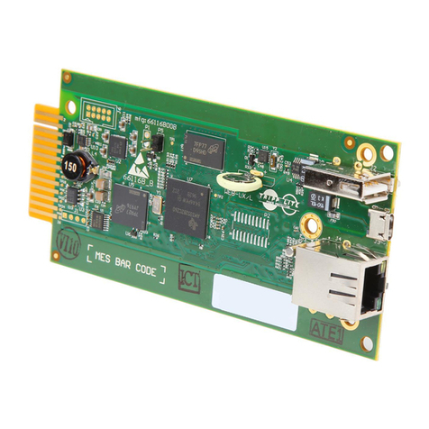
BinTec TBC1-1VDSL2-1 User manual

TBC1-1VDSL2-1 card
Installation Manual
Copyright© bintec Dm 651-I Version 1.2 2017 bintec elmeg
bintec elmeg Manual
TBC1-1VDSL2-1 card 1

Legal Notice
Warranty
This publication is subject to change.
bintec elmeg offers no warranty whatsoever for information contained in this manual.
bintec elmeg is not liable for any direct, indirect, collateral, consequential or any other damage connected to the de-
livery, supply or use of this manual.
Manual bintec elmeg
2TBC1-1VDSL2-1 card

Table of Contents
Chapter1 AboutThisManual................................. 1
1.1 SupportedDevices................................... 1
1.2 Warningandnotes................................... 1
1.3 Who should read this manual? . . . . . . . . . . . . . . . . . . . . . . . . . . . . . . 1
1.4 Whatisinthismanual?................................. 1
1.5 How is the information organized? . . . . . . . . . . . . . . . . . . . . . . . . . . . . 1
1.6 TechnicalSupport ................................... 1
1.7 RelatedDocumentation................................. 2
Chapter 2 TBC1-1VDSL2-1 expansion card . . . . . . . . . . . . . . . . . . . . . . . . . 3
2.1 TBC1-1VDSL2-1 expansion card: Characteristics . . . . . . . . . . . . . . . . . . . . . . 3
2.2 TBC1-1VDSL2-1 expansion card: Connectors . . . . . . . . . . . . . . . . . . . . . . . 4
Chapter 3 Installing the TBC1-1VDSL2-1 expansion card . . . . . . . . . . . . . . . . . . 5
3.1 Requirements prior to installation . . . . . . . . . . . . . . . . . . . . . . . . . . . . . 5
3.1.1 Determining the firmware file . . . . . . . . . . . . . . . . . . . . . . . . . . . . . . . 5
3.2 Installing or replacing the TBC1-1VDSL2-1 expansion card. . . . . . . . . . . . . . . . . . 5
Chapter 4 LEDs and connector pinouts: Description . . . . . . . . . . . . . . . . . . . . . 6
4.1 TBC1-1VDSL2-1 expansion card: LEDs . . . . . . . . . . . . . . . . . . . . . . . . . . 6
4.2 Connectorpinouts ................................... 6
4.2.1 RJ-45Connector.................................... 6
Chapter5 Compliance..................................... 8
5.1 ManufacturerInformation................................ 8
5.2 SafetyWarnings.................................... 8
5.3 WEEEInformation................................... 8
5.4 REACH........................................ 9
5.5 EC Declaration of Conformity. . . . . . . . . . . . . . . . . . . . . . . . . . . . . . . 9
5.6 CEmarking...................................... 9
bintec elmeg Table of Contents
TBC1-1VDSL2-1 card i

Table of Contents bintec elmeg
ii TBC1-1VDSL2-1 card

Chapter 1 About This Manual
This installation guide contains step by step instructions on how to correctly install, uninstall and replace the
TBC1-1VDSL2-1 expansion card in bintec RM3000 / RM5000 / RM7000 routers.
1.1 Supported Devices
The information provided in this installation manual only applies to the TBC1-1VDSL2-1 card.
1.2 Warning and notes
Observe the warnings and instructions set forth in this manual to avoid any injuries or damage during installation and
maintenance. Please follow the security procedures and guidelines when working near electrical equipment. The
warnings and notes are provided in each chapter as appropriate.
1.3 Who should read this manual?
This manual should be read by installers and network administrators who need to install, configure or maintain net-
works. This guide assumes that the installer is familiar with network electronics and technologies.
1.4 What is in this manual?
This installation guide contains the following information:
• A description of the general characteristics of the TBC1-1VDSL2-1 expansion
card.
• A description of the steps to carry out in order to install the TBC1-1VDSL2-1
card in bintec RM3000 / RM5000 / RM7000 routers.
• A description of the TBC1-1VDSL2-1 expansion card LEDs and connector pin-
outs.
1.5 How is the information organized?
This document aims to provide all the information necessary to install the TBC1-1VDSL2-1 expansion card in the
bintec RM3000 / RM5000 / RM7000 router family.
•TBC1-1VDSL2-1 expansion card characteristics.
•TBC1-1VDSL2-1 expansion card connectors.
• Requirements prior to installation.
• Installing the TBC1-1VDSL2-1 expansion card.
1.6 Technical Support
bintec elmeg offers a technical support service. Device software can be upgraded on a regular basis for maintenance
purposes and for new features.
Contact information:
Web: http://www.bintec-elmeg.com
Tel. No.: +49 - 911 - 9673 0
Fax: +49 - 911 - 688 0725
bintec elmeg 1 About This Manual
TBC1-1VDSL2-1 card 1

Email: support@bintec-elmeg.com
1.7 Related Documentation
bintec Dm569-I bintec RM3000 Installation.
bintec Dm741-I ADSL-VDSL
Note
The manufacturer reserves the right to make changes and improvements to the appropriate features in
both the software and hardware of this product, modifying the specifications of this manual without prior
notice.
The images that show the front and back panels of the device are for information purposes only. Some
small modifications may exist in the actual device.
1 About This Manual bintec elmeg
2TBC1-1VDSL2-1 card

Chapter 2 TBC1-1VDSL2-1 expansion card
This manual focuses on the TBC1-1VDSL2-1 expansion card.
VDSL2 stands for Very high bit rate Digital Subscriber Line version 2, which is defined in the ITU G.993.2 and
G.993.5 standards.
VDSL2 has been developed using the ADSL/ADSL2/ADSL2+ technologies as basis, and the main differences areas
follows:
• Upstream and downstream channel multiplicity.
• Supports up to 200 Mbps, symmetric (profile 30a).
• It only uses FDM mode, EC mode is not defined (echo cancellation or carrier
overlapping).
• Allows for a new encapsulation to be used: PTM.
• Multiple link diagnostics.
For further information on ADSL and VDSL technologies, please see the bintec Dm741-I ADSL-VDSL manual.
Fig. 1: TBC1-1VDSL2-1 card
2.1 TBC1-1VDSL2-1 expansion card: Characteristics
The main characteristics of the TBC1-1VDSL2-1 expansion card are as follows
TBC1-1VDSL2-1 card: xDSL characteristics
Ports One RJ-45 VDSL/ADSL port.
ADSL
Standards ANSI:
• T1.413 Issue 2.
ITU-T G.991.1 (G.DMT):
• Annex A: Full Rate ADSL over POTS.
ITU-T G.991.2 (G. Lite) Lite ADSL over POTS.
G.992.3 (ADSL2):
• Annex A: ADSL2 over POTS.
• Annex L: RE-ADSL2 over POTS,
• Annex M: ADSL2 with extended upstream over POTS.
G.992.5 (ADSL2+):
• Annex A: ADSL2+ over POTS.
• Annex M: ADSL2+ with extended upstream over POTS.
bintec elmeg 2 TBC1-1VDSL2-1 expansion card
TBC1-1VDSL2-1 card 3

Downstream Speed 27 Mbps.
Upstream Speed 3 Mbps.
Transfer Mode ATM (Asynchronous Transfer Mode).
Other characteristics Dying Gasp:
• ITU G.991.2 standard recommendation.
VDSL
Standards ITU-T G.993.2 (Annex A and B):
• Profiles: 8a, 8b, 8c, 8d, 12a, 12b, 17a
ITU-T G.993.5 (vectoring).
Downstream Speed Up to 100 Mbps.
Upstream Speed Up to 50 Mbps.
Transfer Mode PTM (Packet Transfer Mode ).
Other characteristics PTM Transmission Convergence (PTM-TC):
• G.993.2 Annex K.
Dual-Latency supported.
Dying Gasp:
• ITU G.991.2 standard recommendation.
2.2 TBC1-1VDSL2-1 expansion card: Connectors
Figure 2 shows the front board of the TBC1-1VDSL2-1 card:
Fig. 2: Front of the TBC1-1VDSL2-1 card
The front board elements are as follows:
Elements table for the front of the TBC1-1VDSL2-1 card
Item Description
AStatus LED
B Link LED
C xDSL port
2 TBC1-1VDSL2-1 expansion card bintec elmeg
4TBC1-1VDSL2-1 card

Chapter 3 Installing the TBC1-1VDSL2-1 expansion card
This chapter provides information on how to install and uninstall the TBC1-1VDSL2-1 expansion card in bintec
RM3000 / RM5000 / RM7000 routers.
This information includes:
• Requirements prior to installation.
• Installing or replacing a TBC1-1VDSL2-1 expansion card.
3.1 Requirements prior to installation
To configure the card, you must be able to access the bintec RM3000 / RM5000 / RM7000 router through a console
or a Telnet connection. For further information, please see the Connecting for configuration section under the bintec
Dm569-I bintec RM3000 Installation manual.
For the TBC1-1VDSL2-1 expansion cards to operate properly, you must load the appropriate firmware file for each
card in the router.
If the firmware has not been loaded in the device prior to installing the card, you can still find out what firmware file
you need.
3.1.1 Determining the firmware file
There are two options to determine the firmware file needed for the installed xDSL card:
3.1.1.1 FTP " quote site listfirmwares" command
The FTP command quote site listfirmwares returns a list containing the names of the firmware files needed for the
device to operate properly:
ftp> quote site listfirmwares
211 fw000016.bfw
ftp>
3.1.1.2 FTP "system firmwares-required" Monitoring command
The system firmwares-required monitoring command displays the same information as the previous command, but
in the local console:
+system firmwares-required
List of required firmwares for detected hardware
------------------------------------------------
Filename Description Version/Subv
------------- ---------------------------- ---------------
fw000016.bfw Lantiq VRX288 TSS-mode v1.0
+
Once the necessary firmware file has been detected, load it onto the device through an FTP connection.
For further information on how to load firmware files in the router, please see the bintec Dm 748-I Software Updating
manual.
3.2 Installing or replacing the TBC1-1VDSL2-1 expansion card.
To install or replace a TBC1-1VDSL2-1 card, please see the Expansion Slot section under the bintec Dm569-I
bintec RM3000 Installation manual.
bintec elmeg 3 Installing the TBC1-1VDSL2-1 expansion card
TBC1-1VDSL2-1 card 5

Chapter 4 LEDs and connector pinouts: Description
This chapter provides information on the TBC1-1VDSL2-1 expansion card LEDs and connector pinouts.
4.1 TBC1-1VDSL2-1 expansion card: LEDs
The TBC1-1VDSL2-1 expansion card for bintec RM3000 / RM5000 / RM7000 routers has three LEDs: STATUS and
LINK.
Fig. 3: TBC1-1VDSL2-1 card
LEDs table of the TBC1-1VDSL2-1 card
Item State
A (Status) OFF: card not detected.
ON: card detected (firmware loaded).
B (Link) OFF: disabled.
Slow blinking: active.
Fast blinking: negotiating.
Steady: synchronized.
4.2 Connector pinouts
The TBC1-1VDSL2-1 expansion card has one RJ-45 connector.
4.2.1 RJ-45 Connector
The following figure shows the RJ-45 connector pinouts.
Fig. 4: xDSL connector
Fig. 5: RJ-45 Connector Pinouts
The following table display the information associated to each connector pinout:
4 LEDs and connector pinouts: Description bintec elmeg
6TBC1-1VDSL2-1 card

TBC1-1VDSL2-1 card RJ-11 Connector Pinouts
RJ-45 pinouts Signal
1 --
2 --
3 --
4 TIP
5 RING
6 --
7 --
8 --
We recommend that you use a 26 AWG cable (at the very least). This may be supplied with the card itself or be de-
scribed in the safety instructions.
Warning
To reduce the risk of fire, only use a 26 AWG cable or a cable with a larger diameter.
bintec elmeg 4 LEDs and connector pinouts: Description
TBC1-1VDSL2-1 card 7

Chapter 5 Compliance
5.1 Manufacturer Information
Brand bintec
Manufacturer bintec elmeg
Country Germany
Postal Address Suedwestpark 94
90449 Nuremberg
Germany
International Phone +49 - 911 - 9673 0
5.2 Safety Warnings
! "
# $ % & & ' ( ) *+
' ,-
5.3 WEEE Information
The waste container symbol with the >X< indicates that the device must be dis-
posed of separately from normal domestic waste at an appropriate waste disposal
facility at the end of its useful service life.
Das auf dem Gerät befindliche Symbol mit dem durchgekreuzten
Müllcontainerbedeutet, dass das Gerät am Ende der Nutzungsdauer bei den
hierfür vorgesehenenEntsorgungsstellen getrennt vom normalen Hausmüll zu
entsorgen ist.
El símbolo del contenedor con la cruz, que se encuentra en el aparato, significa
que cuando el equipo haya llegado al final de su vida útil, deberá ser llevado a los
centros de recogida previstos, y que su tratamiento debe estar separado del de
los residuos urbanos.
5 Compliance bintec elmeg
8TBC1-1VDSL2-1 card

5.4 REACH
In compliance with the REACH Candidate List, the delivered product and product packaging do not contain chemic-
alsubstances above a concentration limit of 0.1% weight by weight (w/w). This declaration will be updated whenever-
any changes occur or other chemical substances are added to the REACH Candidate List. Information is cur-
rentlyprovided to consumers upon request.
5.5 EC Declaration of Conformity
English (EN) Hereby, bintec elmeg declares that the radio equipment type TBC1-1VDSL2-1 is
in compliance with:
Directive 2014/30/EU (EMC)
Directive 2014/35/EU (LVD)
of the European Parliament and of the Council.
Spanish (ES) Español Por la presente, bintec elmeg declara que el tipo de equipo radioeléctrico
TBC1-1VDSL2-1 es conforme con:
Directiva 2014/30/UE (EMC)
Directiva 2014/35/UE (LVD)
del Parlamento Europeo y del Consejo.
German (DE) Deutsch Dieses Gerät entspricht den grundlegenden Anforderungen und den weiteren
entsprechenden Vorgaben der
Richtlinie 2014/30/UE (EMC)
Richtlinie 2014/35/UE (LVD)
Richtlinie 2011/65/UE (RoHS)
des Europäischen Parlaments.
The full text of the EU declaration of conformity and additional product documentation is available at the following in-
ternet address: http://www.bintec-elmeg.com
This equipment is in conformity with the CE procedures and marking.
5.6 CE marking
This equipment is in conformity with CE procedures and marking.
bintec elmeg 5 Compliance
TBC1-1VDSL2-1 card 9
Table of contents
Other BinTec Computer Hardware manuals
Popular Computer Hardware manuals by other brands

Sony
Sony DVCAM DSBK-2020K installation instructions
Intel
Intel SRCSASRB - RAID Controller Hardware user's guide

Renesas
Renesas RL78/G13 Application note
Digital Equipment
Digital Equipment VAX 6000 Model 500 Installing
Smacq Technologies
Smacq Technologies PCI-3000 Series user manual
Supero
Supero AOC-USAS-S4ir user guide
