BINTRAC HouseLink HL-10E User manual

Installation and Operation Manual
HouseLink™ HL-10E
4/25/2018
HouseLink HL-10E
Installation and Operation Manual
Modbus TCP and XML

Installation and Operation Manual
HL-10E Installation Manual Rev 1.03 2Part Number MAN-000012
Table of Contents
Installation Overview...............................................................................................................................................................3
Components............................................................................................................................................................................3
BinTrac Indicator................................................................................................................................................................3
Load Cell Bracket...............................................................................................................................................................3
Smart Summing Box.......................................................................................................................................................... 3
BinTrac Power Supply .......................................................................................................................................................3
HouseLink Model HL-10E.................................................................................................................................................. 3
Installation...............................................................................................................................................................................4
Mounting HouseLink HL-10E.............................................................................................................................................4
Wiring the HouseLink HL-10E Interface ............................................................................................................................4
Setup & Configuration.............................................................................................................................................................5
Initial Setup ........................................................................................................................................................................ 5
Home Page........................................................................................................................................................................5
Devices Page.....................................................................................................................................................................6
BinTrac Device Page .........................................................................................................................................................6
Status Page........................................................................................................................................................................7
Discovery Settings Page....................................................................................................................................................7
Network Settings Page ......................................................................................................................................................8
Help Page ..........................................................................................................................................................................8
XML Interface..........................................................................................................................................................................9
The Index/Error Page......................................................................................................................................................... 9
The Device Detail Report.................................................................................................................................................10
Modbus Packet Data Format ................................................................................................................................................11
Sample Modbus Weight Request ....................................................................................................................................11
Sample Modbus Weight Response .................................................................................................................................11
Sample Fill Request.........................................................................................................................................................12
Sample Fill Response......................................................................................................................................................12
Sample Usage Request...................................................................................................................................................12
Sample Usage Response................................................................................................................................................12
Operational Specifications ....................................................................................................................................................13
is a registered trademark of HerdStar, LLC.
Copyright © 2017 HerdStar®, LLC. All rights reserved.
Printed in the USA
1400 Madison Avenue / Suite 504 / Mankato, MN 56001
PH: 507-344-8005 FAX: 507-344-8009
www.herdstar.com

Installation and Operation Manual
HL-10E Installation Manual Rev 1.03 3Part Number MAN-000012
Installation Overview
This guide covers the mounting and wiring of the HouseLink HL-10E interface. HouseLink interfaces should be placed
indoors.
This symbol means the text has extra importance since it is describing the importance of a feature or
explaining a step to which you should pay close attention to avoid problems, or to which safety is a concern.
Components
A BinTrac system consists of a number of basic components:
BinTrac Indicator
This is the main unit of the BinTrac system. The BinTrac Indicator communicates with the Smart Summing Boxes to
register the weight of feed in the bins and peripheral devices including HouseLink HL-10E. The feed level is computed
and displayed on the LED bar graph. One BinTrac Indicator can display up to four feed bins.
Load Cell Bracket
The Load Cell Bracket allows for easy installation on new or existing bins. Due to the patented design, the bracket does
the lifting and there is no need for time consuming field calibration.
Smart Summing Box
One Smart Summing Box per bin communicates the current reading on the leg brackets to the BinTrac Indicator.
BinTrac Power Supply
This provides the power for the BinTrac system. The power supply converts the line voltage to low voltage.
HouseLink Model HL-10E
The HouseLink 10E (HL-10E) provides an interface to the BinTrac system via Ethernet utilizing Modbus TCP or XML.
Installation and Operation Manual
HL-10E Installation Manual Rev 1.03 4Part Number MAN-000012
Installation
Mounting HouseLink HL-10E
Step 1: The HouseLink HL-10E should be mounted indoors and away from moisture and debris. Additionally, it should be
mounted in or near the peripheral device it is connecting to.
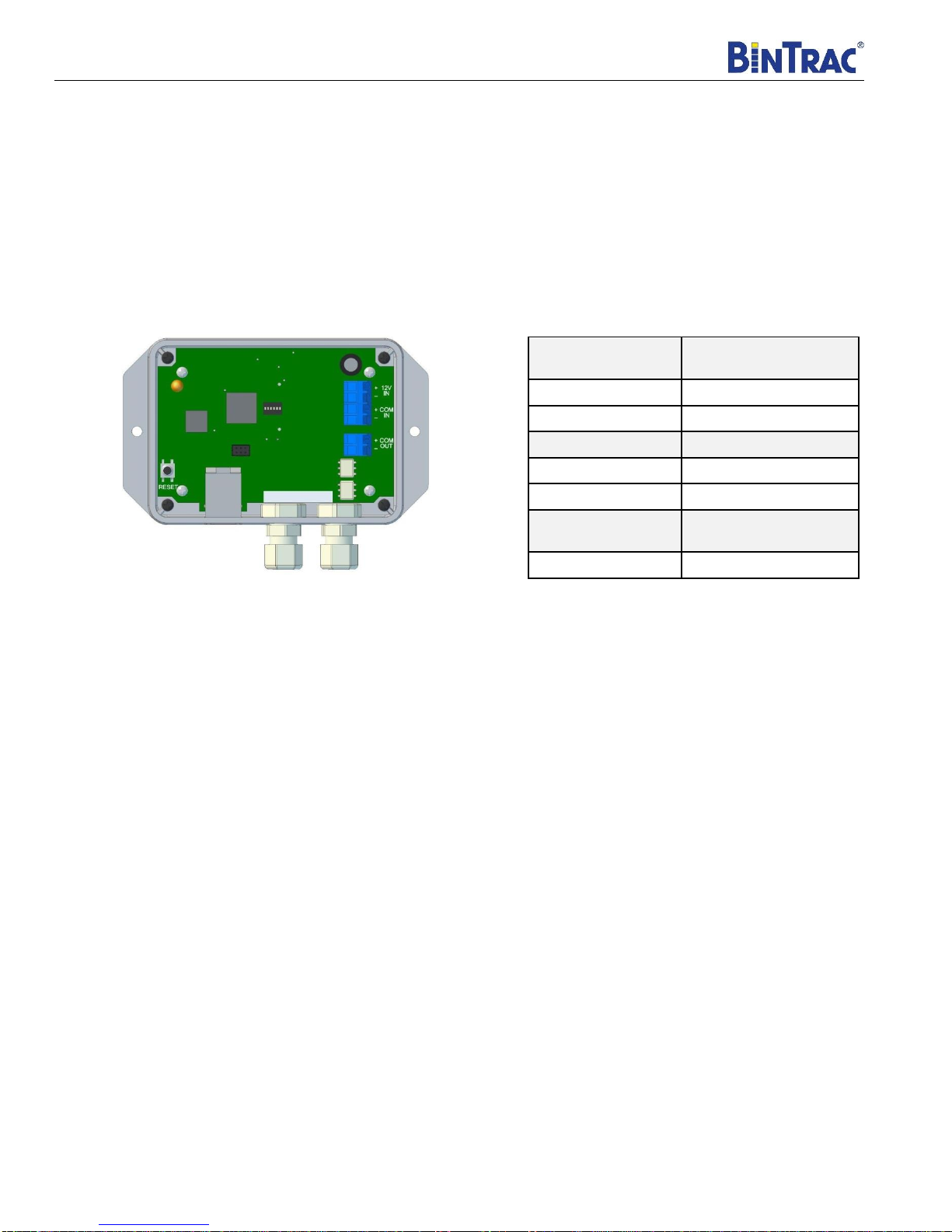
Wiring the HouseLink HL-10E Interface
Step 2: Connect the +12V (IN) and -12V (IN) on the HL-10E to the provided power supply.
Step 3: The +COM (IN) and –COM (IN) on the HL-10E connects to the + SIG and - SIG on the COMM Port of the BinTrac
Indicator.
Step 4: The Ethernet port will connect to a router, PLC, or other house control using a standard CAT5 Ethernet cable.
Reset Button:Pressing and releasing the RESET will put the HL-10E in discovery mode where the device will search for
connected BinTrac devices. The LED will flash quickly and then return to a slow flash once discovery is complete.
HL-10E
BinTrac Indicator
(COMM Port)
+COM (IN)
+12 SIG
-COM (IN)
-12 SIG
HL-10E
Power Supply
+12V (IN)
+12V
-12V (IN)
-12V
HL-10E
House Control/PLC
Ethernet Port
Ethernet Port
Installation and Operation Manual
HL-10E Installation Manual Rev 1.03 5Part Number MAN-000012
Setup & Configuration
Initial Setup
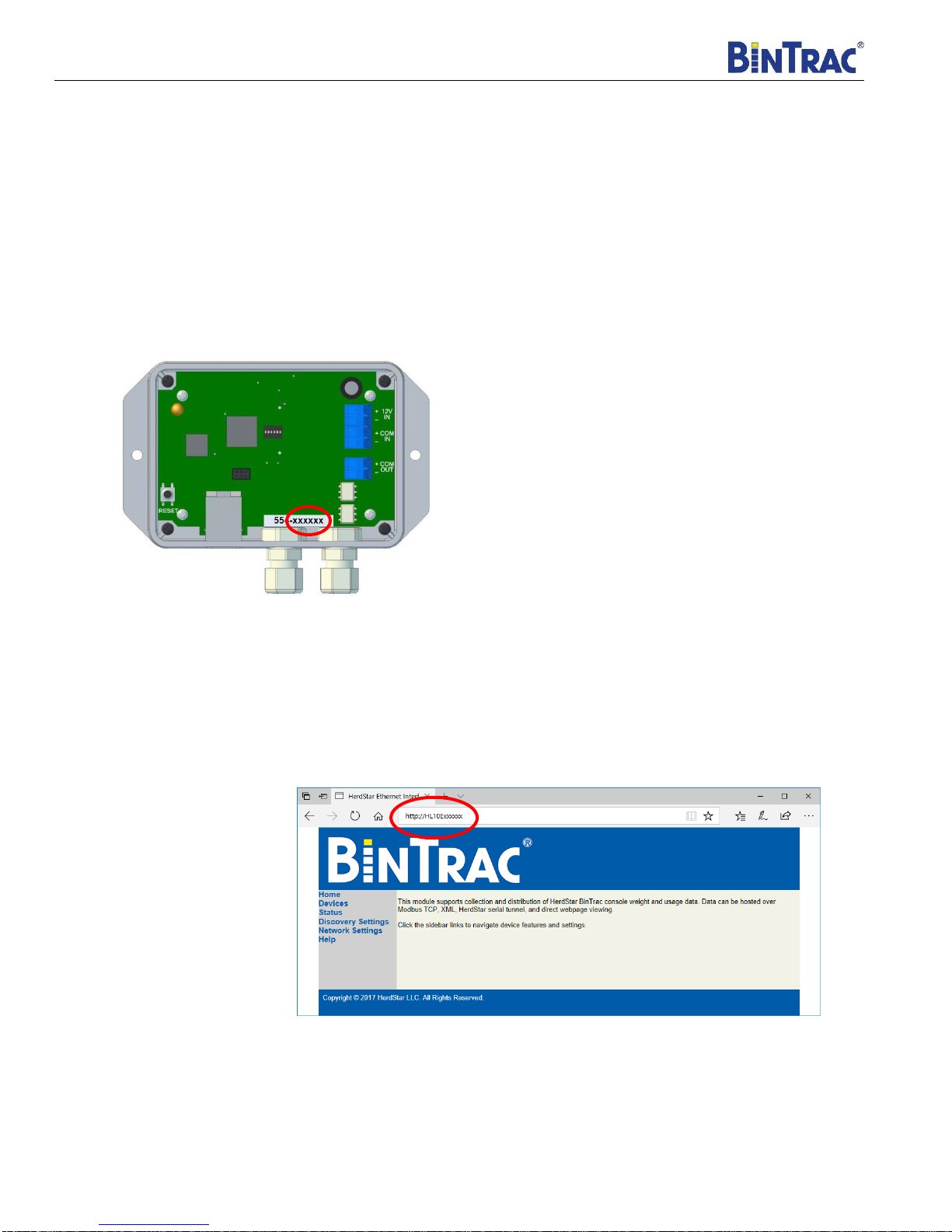
1. Connect the HL-10E to a DHCP enabled Local Area Network(LAN).
2. Open a web browser on any device connected to the same LAN as the HL-10E.
3. Type in http://HL10Exxxxxx/ where “xxxxxx” equals the serial number on the HL-10E that comes after the three-digit
date code. (Circled below)
4. Initially, a password is not required, the device will go directly to the Home page. If a password is used, the login
screen will pop up, simply enter “admin” for the username and “AAAAA” as the default password and the device will
then display the Home page. See “Network Settings” for more information regarding setting the password.
Home Page
Installation and Operation Manual
HL-10E Installation Manual Rev 1.03 6Part Number MAN-000012
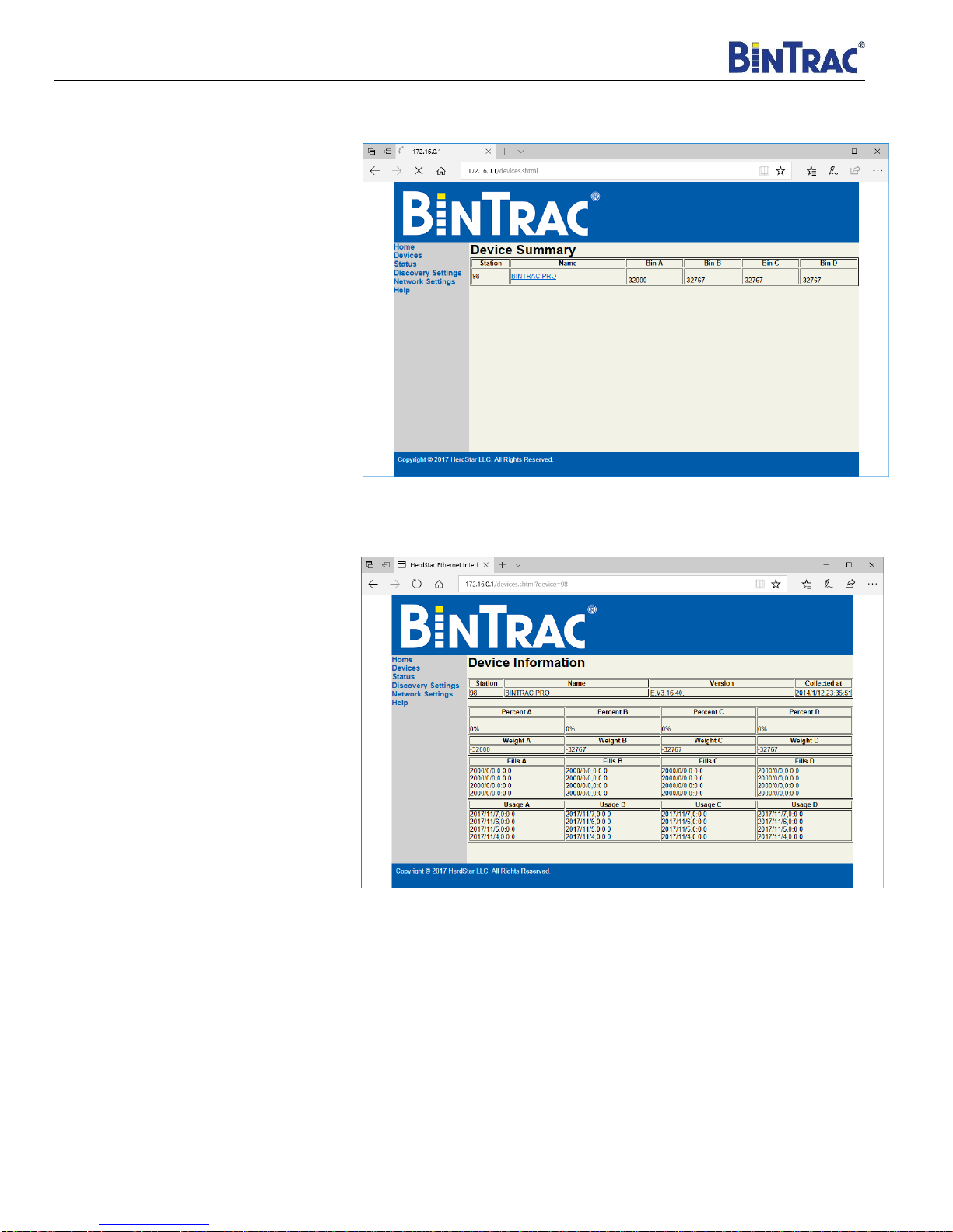
Devices Page
•Identifies connected devices and
current weights of each bin.
BinTrac Device Page
•Clicking on the individual devices
brings up details about each bin
such as weights, percentages and
the firmware version of the
BinTrac Indicator.
Installation and Operation Manual
HL-10E Installation Manual Rev 1.03 7Part Number MAN-000012
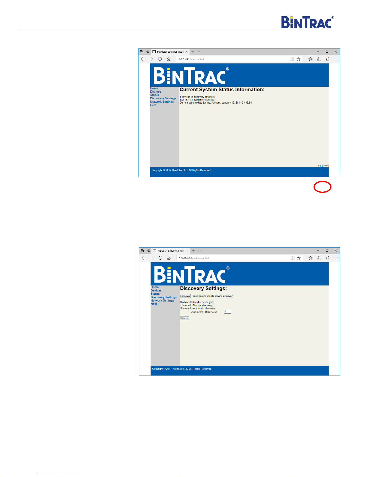
Status Page
•Identifies the number of BinTrac
devices and the IP address of the
HL-10E.
•Additionally, the firmware version
of the HL-10E device is located in
the bottom right corner of this
page.
Discovery Settings Page
The discovery settings page allows you to
view and edit your discovery settings.
•Press the discovery button to
initiate a device discovery. This
can also be done by pressing the
reset button on the HL-10E
device.
•The HL-10E device has an auto
discovery feature that can be
modified by changing the
“Discovery Interval” number
(minutes) and pressing the
submit button. The auto discovery
feature can also be disabled to
avoid interruption in situations of
consecutive information pulling
such as Modbus and XML.
Installation and Operation Manual
HL-10E Installation Manual Rev 1.03 8Part Number MAN-000012
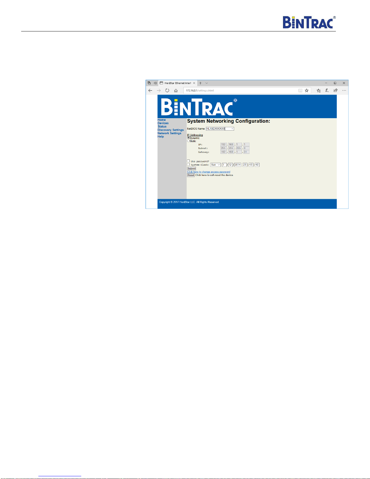
Network Settings Page
The network settings page displays the current NetBIOS name, dynamic or static IP addressing and the system clock.
You may change the IP addressing by selecting “Static”and making the appropriate changes. This page also allows you
to adjust the password settings.
•NetBIOS Name:
•Max 16 characters
•Must use only
uppercase letters
•Alpha-numeric
•No special characters
•The static IP address requires
the IP address as well as the
Subnet Mask and Gateway IP.
Changing these can make the
device not work so be sure of
the changes before pressing
submit.
•The system clock can be
updated for the current date
and time. Adjust the time,
check the box and press
submit to proceed with the
changes.
•A password can be used to protect the access of the HL-10E device. To use this feature, check the “Use
password?” box and click submit to apply changes.
•The password can be changed by using the “Click here to change access password” link. Password must
NOT exceed 9 characters and contain NO special characters (Alphanumeric characters only).
Help Page
The Help page can answer some of the more common issues. If you continue to have problems, please call 1-877-
BINTRAC for technical assistance.
Installation and Operation Manual
HL-10E Installation Manual Rev 1.03 9Part Number MAN-000012
XML Interface
The XML interface can be used by developers or advanced users to get detailed information from the BinTrac indicators
or set up an automated collection scheme. The XML interface responds to POST requests at the XML generation page
found at: http://HL10Exxxxxx/generateXML.xml
Query strings can be used to select individual BinTrac indicators which have been properly set up and discovered as
follows: http://HL10Exxxxxx/generateXML.xml?device=22
The XML interface returns two distinct page types: an index/error page, and a device detail report. See below for example
of these pages and short explanations.
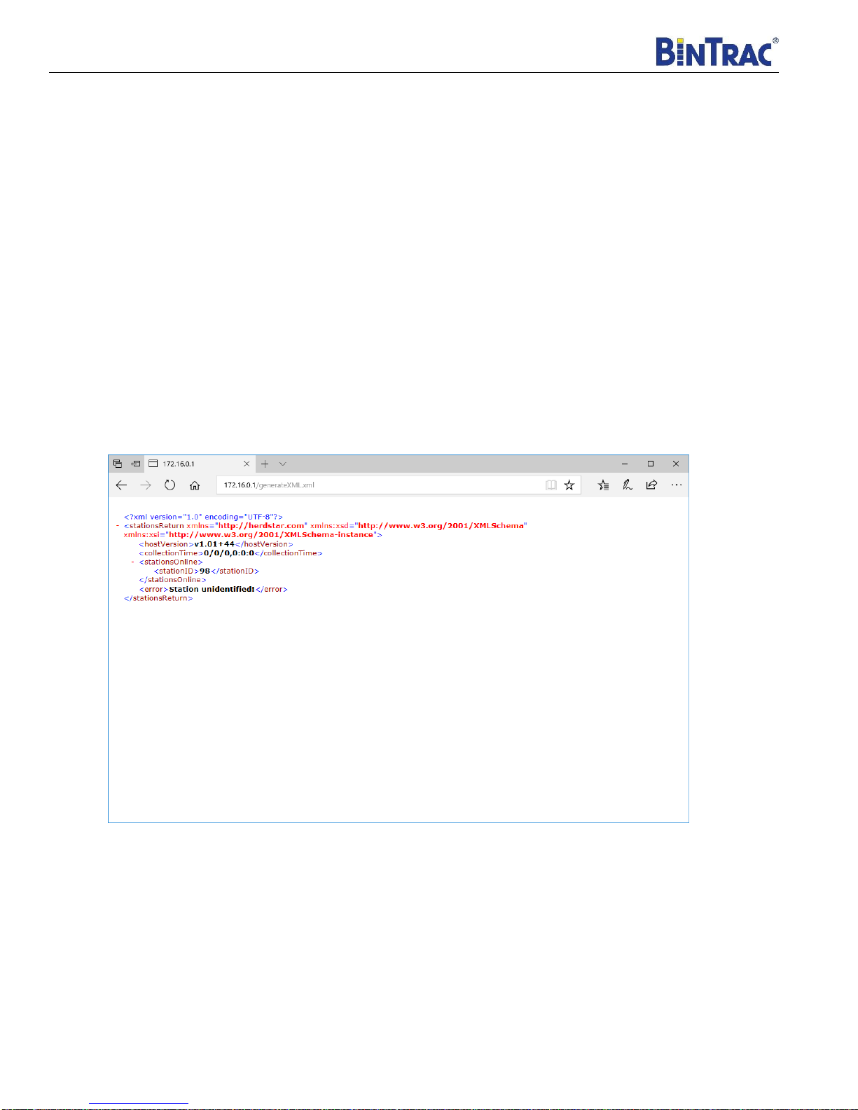
The Index/Error Page
This page is returned when the XML interface is accessed with no query string, an invalid string, or a query string pointing
to a device that is not discovered.
hostVersion Indicates the firmware version present on the HL10E device.
stationsOnline Returns a list of discovered BinTrac indicators.
error Displays “Station unidentified” when a BinTrac indicator isn’t found.
Installation and Operation Manual
HL-10E Installation Manual Rev 1.03 10 Part Number MAN-000012
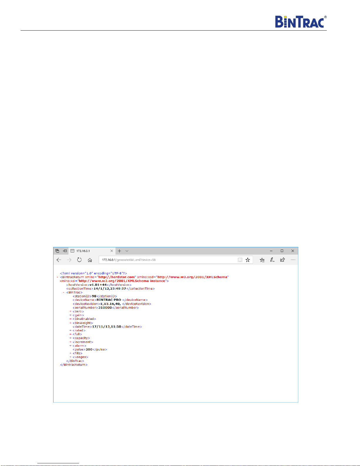
The Device Detail Report
This page is returned when the XML interface is provided a valid discovered BinTrac station ID. The page displays
internal data and settings from the BinTrac indicator.
stationID Locally unique identifier.
deviceName Device name string.
deviceRevision Device firmware version string.
serialNumber Factory serial number.
zero The zero represents the empty weight of the bin.
gain A value used to scale raw counts to user standard measurement units.
binsEnabled Lists whether each bin is enabled or not.
binWeight Bin weight as measured by the BinTrac indicator.
dateTime Current date and time as configured on the indicator.
rated mV/V rating setting of for the connected load cells.
full User value defining the weight that a bin is considered to be full.
capacity Specified load cell capacity sum.
increment Smallest units that the BinTrac display will count by.
alarm A user defined weight value to flip a relay output.
pulse If a pulse output is enabled, this value holds the number of pulses per unit weight.
fills Timestamped fill weight data.
usages Timestamped usage weight data.
Installation and Operation Manual
HL-10E Installation Manual Rev 1.03 11 Part Number MAN-000012
Modbus Packet Data Format
The Modbus module responds to an input register point type (4), at address 1000 with a length of eight bytes. The
Modbus device ID will match to the BinTrac Indicator station ID as configured in the setup menu of the BinTrac indicator.
A discovery must be done before any units will respond.
Below are sample Modbus request and response packets:
Sample Modbus Weight Request
[4c][02][00][00][00][06][0b][04][03][e7][00][08]
HEX
DESCRIPTION
DECIMAL
4c02
TRANSACTION ID
19458
0000
PROTOCOL ID
0
0006
# OF BYTES
6
0b
DEVICE ID
11
04
INPUT REG
4
03e7
ADDRESS
1000
00008
LENGTH
8
Sample Modbus Weight Response
[4c][02][00][00][00][13][0b][04][10][ff][ff][80][01][ff][ff][80][01][00][00][6b][6e][ff][ff][80][01]
HEX
DESCRIPTION
DECIMAL
4c02
TRANSACTION ID
19458
0000
PROTOCOL ID
0
0013
# OF BYTES
19
0b
DEVICE ID
11
04
INPUT REG
4
10
SIZE
16
ffff8001
BIN A
-32767
ffff8001
BIN B
-32767
00006b6e
BIN C
27502
ffff8001
BIN D
-32767

Installation and Operation Manual
HouseLink™ HL-10E
4/25/2018
Sample Fill Request
HEX
DESCRIPTION
DECIMAL
8B00
TRANSACTION ID
35584
0000
PROTOCOL ID
0
0006
# OF BYTES
6
09
DEVICE ID
9
04
INPUT REG
4
04AF
ADDRESS
1200
0012
LENGTH
18
Sample Fill Response
HEX
DESCRIPTION
DECIMAL
8B00
TRANSACTION ID
35584
0000
PROTOCOL ID
0
0027
# OF BYTES
39
09
DEVICE ID
9
04
INPUT REG
4
24
SIZE
36
11
YEAR
17
08
MONTH
8
1A
DAY
26
07
HOUR
7
09
MINUTE
9
000002E1
BIN A
737
11
YEAR
17
08
MONTH
8
1A
DAY
26
07
HOUR
7
37
MINUTE
55
00009F98
BIN B
40856
11
YEAR
17
08
MONTH
8
1D
DAY
29
08
HOUR
8
0A
MINUTE
19
00003D0D
BIN C
15629
11
YEAR
17
08
MONTH
8
0F
DAY
15
14
HOUR
20
02
MINUTE
2
00011C41
BIN D
72769
Sample Usage Request
HEX
DESCRIPTION
DECIMAL
9200
TRANSACTION ID
37376
0000
PROTOCOL ID
0
0006
# OF BYTES
6
09
DEVICE ID
9
04
INPUT REG
4
0577
ADDRESS
1400
0012
LENGTH
18
Sample Usage Response
HEX
DESCRIPTION
DECIMAL
9200
TRANSACTION ID
37376
0000
PROTOCOL ID
0
0027
# OF BYTES
39
09
DEVICE ID
9
04
INPUT REG
4
24
SIZE
36
11
YEAR
17
08
MONTH
8
1D
DAY
29
00
HOUR
0
00
MINUTE
0
000003E4
BIN A
996
11
YEAR
17
08
MONTH
8
1D
DAY
29
00
HOUR
0
00
MINUTE
0
00001DD2
BIN B
7634
11
YEAR
17
08
MONTH
8
1D
DAY
29
00
HOUR
0
00
MINUTE
0
00006514
BIN C
25876
11
YEAR
17
08
MONTH
8
1D
DAY
29
00
HOUR
0
00
MINUTE
0
00004308
BIN D
17160

Installation and Operation Manual
HL-10E Installation Manual Rev 1.03 13 Part Number MAN-000012
Operational Specifications
Operating Temperature Range: -40°C to +60°C (-40°F to +140°F)
Humidity: 5% to 95% (non-condensing)
Environmental Air: No corrosive gasses permitted
Shock and Vibration: Suitable for installation on stable surfaces
Enclosure Type: Unsealed
Agency Approvals: N/A
Wiring Type: Screw terminal blocks plus RJ45 jack
Power Requirements: 10.5VDC –13.5VDC, 160mA (typ @ 12.0VDC)
(Current depends on port loading)
Serial Flash Memory: 16Mb
Real-Time Clock/Calendar: Present
Ethernet Communication Port: Single 10/100 Base-T with status indicators
COM IN/OUT Serial Communication Interfaces: HerdStar optically isolated (proprietary)

Installation and Operation Manual
HL-10E Installation Manual Rev 1.03 14 Part Number MAN-000012
Legal
Portions of this device’s firmware are ported from freemodbus and Contiki os available at http://freemodbus.org and http://www.contiki-os.org,
respectivly. The following disclaimers are required by the respective authors:
All rights reserved.
Redistribution and use in source and binary forms, with or without
modification, are permitted provided that the following conditions are met:
1. Redistributions of source code must retain the above copyright notice, this list of conditions and the following disclaimer.
2. Redistributions in binary form must reproduce the above copyright notice, this list of conditions and the following disclaimer in the
documentation and/or other materials provided with the distribution.
3. The name of the author may not be used to endorse or promote products derived from this software without specific prior written
permission.
THIS SOFTWARE IS PROVIDED BY THE AUTHOR ``AS IS'' AND ANY EXPRESS OR
IMPLIED WARRANTIES, INCLUDING, BUT NOT LIMITED TO, THE IMPLIED WARRANTIES
OF MERCHANTABILITY AND FITNESS FOR A PARTICULAR PURPOSE ARE DISCLAIMED.
IN NO EVENT SHALL THE AUTHOR BE LIABLE FOR ANY DIRECT, INDIRECT,
INCIDENTAL, SPECIAL, EXEMPLARY, OR CONSEQUENTIAL DAMAGES (INCLUDING, BUT
NOT LIMITED TO, PROCUREMENT OF SUBSTITUTE GOODS OR SERVICES; LOSS OF USE,
DATA, OR PROFITS; OR BUSINESS INTERRUPTION) HOWEVER CAUSED AND ON ANY
THEORY OF LIABILITY, WHETHER IN CONTRACT, STRICT LIABILITY, OR TORT
(INCLUDING NEGLIGENCE OR OTHERWISE) ARISING IN ANY WAY OUT OF THE USE OF
THIS SOFTWARE, EVEN IF ADVISED OF THE POSSIBILITY OF SUCH DAMAGE.
Copyright (c) 2001-2003, Adam Dunkels.
All rights reserved.
Redistribution and use in source and binary forms, with or without
modification, are permitted provided that the following conditions are met:
1. Redistributions of source code must retain the above copyright notice, this list of conditions and the following disclaimer.
2. Redistributions in binary form must reproduce the above copyright notice, this list of conditions and the following disclaimer in the
documentation and/or other materials provided with the distribution.
3. The name of the author may not be used to endorse or promote products derived from this software without specific prior written
permission.
THIS SOFTWARE IS PROVIDED BY THE AUTHOR ``AS IS'' AND ANY EXPRESS OR
IMPLIED WARRANTIES, INCLUDING, BUT NOT LIMITED TO, THE IMPLIED WARRANTIES
OF MERCHANTABILITY AND FITNESS FOR A PARTICULAR PURPOSE ARE DISCLAIMED.
IN NO EVENT SHALL THE AUTHOR BE LIABLE FOR ANY DIRECT, INDIRECT,
INCIDENTAL, SPECIAL, EXEMPLARY, OR CONSEQUENTIAL DAMAGES (INCLUDING, BUT
NOT LIMITED TO, PROCUREMENT OF SUBSTITUTE GOODS OR SERVICES; LOSS OF USE,
DATA, OR PROFITS; OR BUSINESS INTERRUPTION) HOWEVER CAUSED AND ON ANY
THEORY OF LIABILITY, WHETHER IN CONTRACT, STRICT LIABILITY, OR TORT
(INCLUDING NEGLIGENCE OR OTHERWISE) ARISING IN ANY WAY OUT OF THE USE OF
THIS SOFTWARE, EVEN IF ADVISED OF THE POSSIBILITY OF SUCH DAMAGE.
Table of contents
Popular Recording Equipment manuals by other brands


Paia
Paia CS-87 Assembly and using manual

Tucker-Davis Technologies
Tucker-Davis Technologies UZ2 Hardware reference

MicMix Audio
MicMix Audio Dynaflanger 265 operating instructions

Shure
Shure MV88+ manual

Elby Designs
Elby Designs EURO SERGE ES21 Series Construction guide

Millennia
Millennia STT-1 quick start guide