The
parts
that
constitute
the
CS-87
cassette
interface
option
fit
entirely
on
the
8700
Computer/Controller
board.
CS•87 ASSEMBLY
Jnstall
the
following components on a PROPERLY OPERATING 8700
Computer
Controller
circuit
board.
00
NOT
proceed
with
the
assembly
of
this
option
until
the
8700
has
been
fully
verified
as
being
operational.
Remove
all
power
and
peripheral
connectors
from
the
8700
before
proceedilig with
the
CS-87
installation.
All
of
the
DOs and
DON
'T
s
that
w_ere
mentioned
in
the
assembly
manual
for
the
8700 apply
here
also.
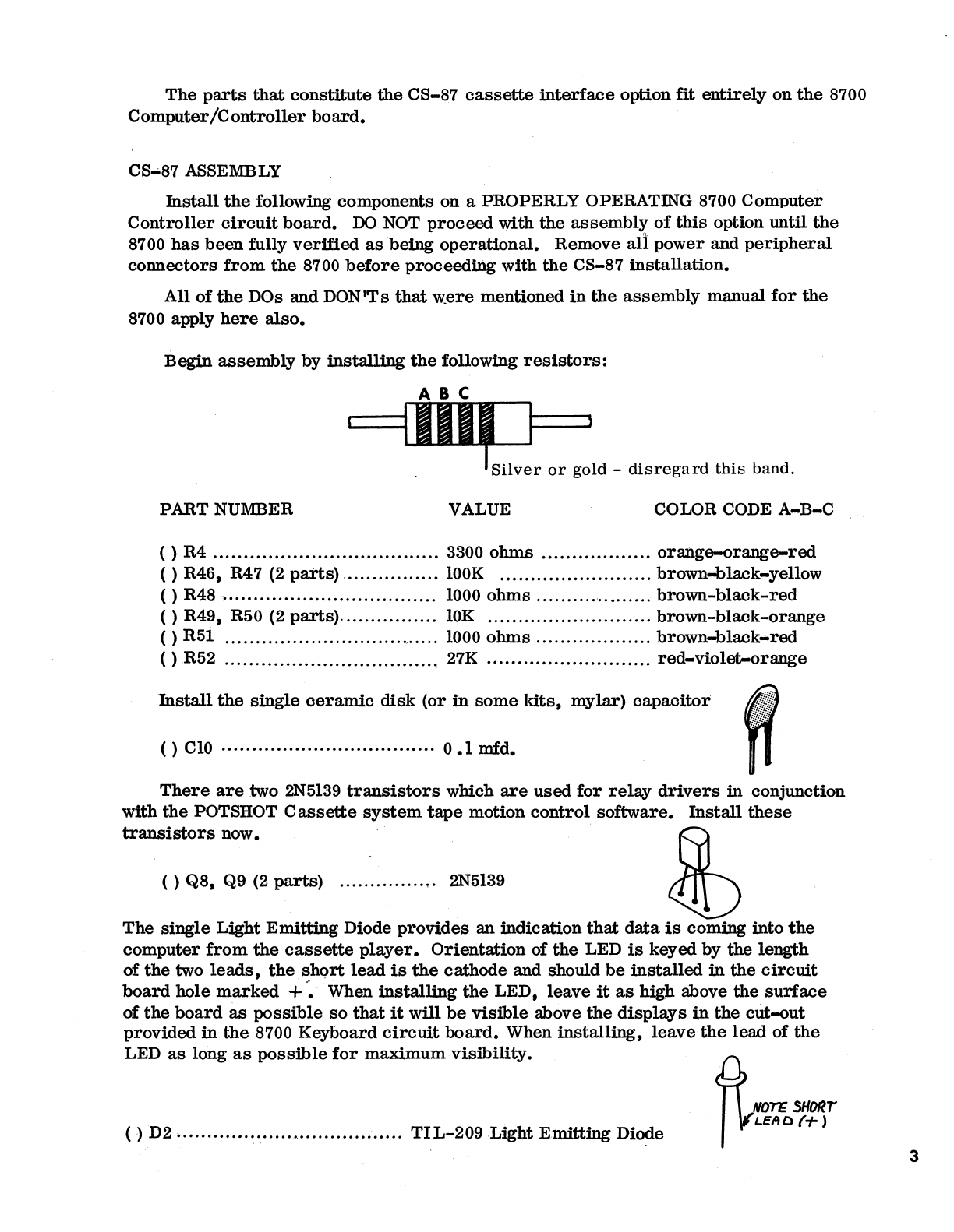
Begin
assembly
by
installing
the
following
resistors:
ABC
1111,
1 1
.Silver
or
gold -
disregard
this
band.
PARTNUMBER
VALUE COLOR CODE
A-B-C
( )
R4
.....
„.
„ „
....
„ „ „
..
„
...
„.
„ „ „ 3300
ohms
„.
„ „ „ „ „ „
...
orange-orange-red
( ) R46, R47 (2 pai'ts) .
„.„.
„.
„ „ „
lOOK
„.
„.
„ „
„.
„ „ „
„.
„.
brown-black-yellow
( ) R48 •„ „ „ „ „ „ „ „
„.
„.
„ „ „ „ „ „ 1000
ohms
„ „ „ „ „ „
.„
„ „
brown-black-red
()
R49, R50 (2
parts).„„„„„„„.
lOK
.„„„„„„„„„„„„„
brown-black-orange
( )
R5i
;„ „ „ „ „ „ „ „ „ „ „ ..„ „
..
„
„.
1000
ohms
„ „ „ „
„.
„.
„
„.
brown-black•red
( ) .R52 „ „ ..„
„.
„
...
„
...
„
.....
„ ..
„,
27K „
„.
„ „
„.„.
„
....
„
„..
recl-violet-orange
Jnstall
the
single
ceramic
disk
(or
in
some
kits,
mylar)
capacitor
() c
10
„ „
„.
„ „ „ „ „ „ „ „
..
„ „ „ „ „ 0
.1
mfd.
There
are
:two
2N5139
transistors
wbich
are
used
for
relay
drivers
in
conjunction
with
the
POTSHOT C
assette
system
tape
motion
control
software.
lnstall
these
transistors
now.
(5)
( )
Q8,
Q9 (2
parts)
„ „ „ „
„.
„...
2N5139
~
The
single
Light
Emitting
Diode
provides
an
indication
that
data
is
coming
into
the
computer
from
the
cassette
player.
Orientation
of
the
LED
is
keyed
by
the
length
of
the
two lea.d.s,
the
sb.Qrt
lead
is
the
cathode
and should
be
installed
in
the
circuit
board
hole
marked
+-.
When
installing
the
LED,
leave
it
as
high
above
the
surface
of
the
board
as
possible
so
that
it
will
be
visible
above
the
displays
in
the
out-out
provided
in
the
8700 Keyboard
circuit
board.
When
installing,
leave
the
lead
of
the
LED
as
long
as
possible
for
ma.ximum
visibility.
()
D2
.„.„„„
..
'.
..
„„
.•
„„„„„„„.„.
TIL-209
Light
Emitting
Diode
4f
UTE
SllOllT
1
~EAO{+)
3