MicMix Audio Dynaflanger 265 User manual

ltlode
| 265
trlYNAFLANGEFI
OPERATINGINSTRUCTIONS

ltlode
I 265
trlYIVAFLANGER'T
OPERATINGINSTRUCTIONS
UNBALANCED
INPUT
INPUT GAIN
ADJUST INPUT
LEVEL OPERATING LEVEL
INOICATORS
BALANCEDINPUT BALANCEDOUTPUT
CVRANGE
I
NOICATORS
CV OUTPUI
NORMAL
MODULATOR CVTRACKING
ulnuar
PEAKOETECTOR
I I
SLOPE
INVERTER
H.F VCO
INVERT
2
Copyright
1978
itlClllX
Audio
Products,Inc.
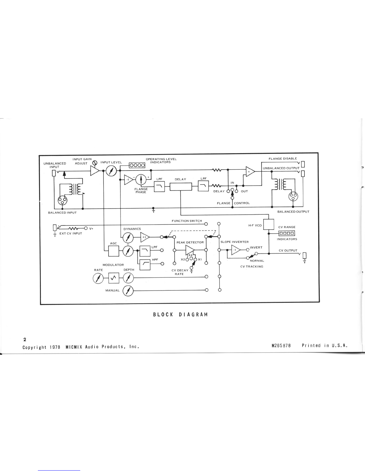
BLOCK DIAGRAM
it265878 Printedin U.S.A,
o
o
o
o
-
o
d
G
o
0
o
@
ut
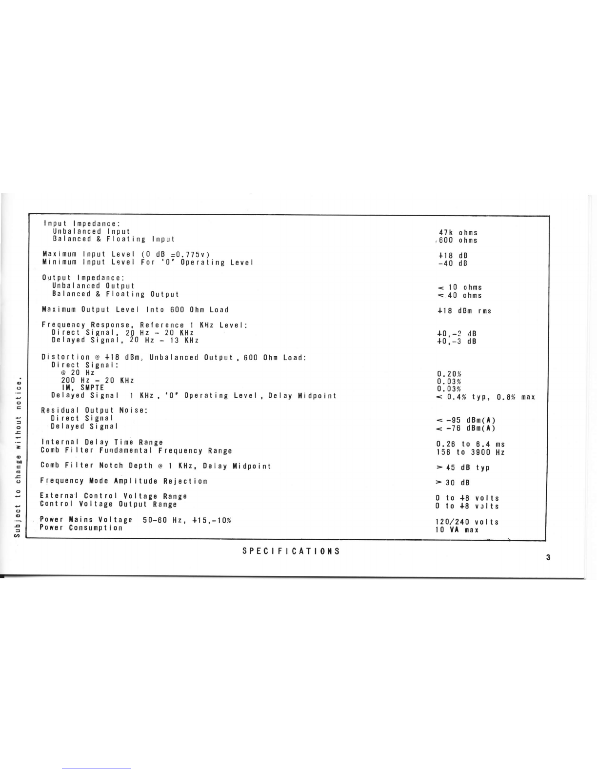
Input lflpedance:
Unbalanced
Input
Balanced
& Floating Input
l{aximumInput Level (0 dB -0.775v)
llinimum
Input Level For '0'0perating Level
0utput lmpedance:
Unbalanr:ed
0utout
Ealanced
& Floating 0utput
llaximum0utput Level Into 600
0hmLoad
Frequency
Response.
Ref
erence I KHzLevel:
Direct Signal, 20 Hz - 20 KHz
0elayed
Signal, 20 Hz
- t3 KHz
Distortion @+18 dBn, Unbalanced0utput.600
0irect Signal:
@
20 Hz
200 Hz
- 20 KHz
IT. STPIE
Dalayed
Signal I (Hz,'0'0perating Level
Residual 0utput Noise:
Direct Signal
0e
layed S
igna
I
internal Delay Tirne
Range
Comb
Filtar Furrdamental
FrequencyRange
Comb
Fi
lter Notch 0epth @
1 l(Hz.0elay tidpoint
Frequency
llodeAmpl
ituda Re.lection
Extarnal Control Voltage Range
Contro
I Vo
I
tage 0ut
put Range
Power
llains Voltage 50-60 Hz, +19,-10%
Powsr
Consumption
0hmLoad:
,0elay llidpoint
47k ohms
.600 o
hms
+t
I dB
-40 dB
< 10 ohms
< 40 ohms
{l I dBmrms
+0,
-? dB
+0,-3 dB
0
.2070
0
.03%
0
.03%
< 0.4%typ, 0.8%
nax
< -95 dBm(A)
< -76 dBm(A)
0.26 to 6.4 ms
156 to 3900Hz
> 45 dB typ
>30 d8
0 to +8 volts
0 to {8 volts
120./210
volts
'|
0 VA max
3
sPECrFrCATt0l{S
DYNAFLANGER
OPERATING
INSTRUCTIONS
INTRODUCTION
Both "phasing" and "flanging" refer to the effects
generated
inan
audiooutputbycombining
two identicalin-
putsignals,except
thatoneof thesignalshasbeenshifted
intime.In
phasing,
oneof thesignals
ismodifiedbypass-
ingitthroughanelectronic
phase-shift
network.Whencom-
binedwiththeoriginalsignal,thechange
in phase
relation-
shipat certain
frequencieswill cause
cancellationsand re-
inforcemenlsof particular
frequenciesattheoutput.
Thesecomb
f
ilter
peaks
andnotchesareoctave
relatedin
a phasing
deviceand the total number is proportionate
to
the numberof filtersin the network.In flanging,the can-
cellationsandreinforcementsare
harmonicallyrelated.
Practicaldelaytimes for audioflangingaregenerally
in
the rangeol t/a
lo 6 milliseconds.Since time (period)
is
equalto 1/f
(frequency),
this correspondsto a fundamental
frequencyrangeof approximately150to 4,000Hz.This re-
lativelynarrow bandwidth is sufficient becauseflanging
createsa harmonicallyrelatedstructure,althoughtheover-
all bandpassof the delayedsignal in a flanger must ap-
proach
thatol the
directsignal.
lf, for example,the delaytime is set lor one millisecond
andthe two signalsare
phase
coherent,there
willbea rein-
forcementof theoutput signalat 1kHz
(1/0.001
= 1,000).A
500 Hz signal,however,
will have undergone
'1800
phase
shift after one millisecond of delay and will theretore
cancel,as will all odd multiplesof 500Hz,
while the even
multipleswillreinforce.
With the developmentof solid statedelaydevices,tape
flanginghas generallygivenway to the more precise
and
moreeasilycontrolledelectronictime delaytypeof equip-
ment. Electronics
havealso allowedthe delaytime to be
4
automatically
varied
or swept backand forth at a pre-set-
table rate, or to be controlled by an externally
applied
voltage,
orto trigger
wheninputsignalamplitudereachesa
pre-set
level.
Whilemore
precise
andeasierto use,electronicflangers
have
sofarbeenashit-or-miss
in
their
applicalion
to a parti-
cular program signal as the original tape flanging tech-
nique.To be truly effective,
the flangingeffect must not
onlybe relatedto program
content,it shouldbe
controlled
by the program
materialautomalically,in accordancewith
theconditionssetbytheoperator
for
thedesiredeffect.
DYNAFLANGER
provides
this capability.In its dynamic
modes,it will respondautomatically
to the frequency
con-
tent of the program
materialin either a high passor low
passfilter mode.lt will also respondautomatically
to the
peak
amplitudes
of the program.
lts responsecantrackthe
frequency
or amplitude
of the inputsignalin eithera nor-
mal or inverse
relationship,
and its control voltage
decay
can be set for fast, medium or slow to best suit the pro-
gram
content.
DYNAFLANGER
alsoprovides
manual
controlcapability
aswellasasweptmodulatorwithvariable
rateanddepth.lt
will acceptan externalcontrolvoltageinput and provides
anoutputof its internally
generated
control
voltage.
Defeat
of the flanging
action is possible
throughuseof the front
panel
switch or by anexternalswitch connectedto theap-
propriate
jack
ontherear
panel.
Simple to operate and extremely versatile,DYNA-
FLANGERunitsare capableof far greater
elfectswhen
used
in pairs,
wilh controlof one beingslavedto theCV
outputof lheother.
Innumerablecombinationsof tracking
reversal,CVdecayrates,CVdynamics
andphasing
canbe
applied
to achieve
effects
rangingfrom
the
very
subtleto
the highly dramatic.One particular
use of a DYNA-
FLANGERis doubling,
not in timebut in pitch,
while
two

units slavedcan also functionas an effective
stereosyn-
thesizer.
POWERINGTHE
UNIT
A voltageselector
switch is accessible
througha cutout
in
thetopcoverof theunit.
WARNING: Verifythatcorreclvollage
has
been
selectedon the internalseleclor
switchBEFORE
applying
lanevoltage
to
theunit.
An IEO-type
connectoris utilized
for power
connections.
Themating
cordfurnishedwith
theunit
is
3-conductorwith
the
following
colors:
Black
-
Line
(High)
White
-
Neutral
(Low)
Green
-
Earth&
ChassisGround
A oower switch and neon indicatorare locatedon the
front
panel.
The
power
switchis
adouble-poletypewiththe
second
pole
operatinga time-delayrelayconnected
to the
output signal.Upon
turn-on,therewill be approximately
3
seconds
delaybeforean output signal appears.This per-
mits
thedelay
line
to settledownandprevents
undesirable
"glitches" from appearingat the output which might dam-
agemonilorspeakers
during
the
initiation
period,
andalso
climinatesany "thump" in the output when the unit is
turnedoff.
SIGNAL
CONNECTIONS
Signal
connectionsmayutilize
eitherthe balanced
(XLR)
ortheunbalanced
(phone
jack)
connectors.
The
unbalanced
input
connectorcontainsa shuntwhich disconnectsthe
balanced input whenevera plug is inserted.Output is
provided on both balancedand unbalanced
connectors
simultaneously.
Balancedinput impedance
is 600 ohms (floating)
and
unbalanced input impedance is 47K ohms. Output
impedancesare low and will readilydrivea 600ohm line
(balanced
or unbalanced.)Fora 5K ohm input impedance,
the 620 ohm resistor across the terminals of the XLR
connector
may
beremoved,
but somedegradationof impe-
dance
vs.frequencywill result
and such practice
is not re-
commended.
XLRconnections
are:
Pin
1
-
Ground,
Pin2 -
Signal
Low,
Pin
3
-
Signal
High.
Phone
iack
connections
areTip
-
Signal
High,Sleeve
-
SignalGround.Phone
jacks
utilizeinsulated
sleevesto provide
single point chassisgroundingin the
unit.
INPUTLEVEL
&CONTROL
DYNAFLANGERwill operatewith nominalinput levels
rangingfrom18dB.aboveto 40
dBbelowareferenceof0dB
= 0.775
volts. The INPUT LEVEL control allows full
attenuationand
provides
upto 6 dB of gain.
An additional

40dBofgain
isavailable,
if required,byadjustment
ofthe
GAINtrimmer
potentiometer
which
isaccessiblethrough
the
front
panel.
For a nominal +4 dBm input signal,
the gain trim
potentiometer
should be set at minimum and the level
control at approximately
75o/"rotation.
With no flanging
effect
(flange
defeated),
thedesign
lossattheoutputisap-
proximalely
0 dB.
Withthe flanging
effect in operation,
the
design gain at the output is approximately
6 dB. These
values provide the optimum performance in terms of
residualnoiseand
distortion.
OPERATING
LEVELINDICATORS
These
indicators
monitorthe peak
signal
levelsentering
thedelay
line
portion
of the unitratherthanthe basic
input
signal.
The INPUT
LEVELcontrolshouldbe adiusted
such
that peakprogram
signals
causethe yellow
("0") indicator
to illuminateat least80% of the time,
andthe red
("+5)
indicatorto illuminateup to 50% of the time,
depending
upon the natureof the transients
present
in the program
material.
6
MODE
SELECTION
Six basic modes of operation
can be selected by the
push-button
switch.
ThreemodEs
provide
direct
(or
indirect)
operatorcontrol while the other three provide
automatic
dynamic
response.
DIRECTCONTROL
Manual
Modulator
External
DYNAMICCONTROL
LowPassFilter
HighPassFilter
EnvelopeFollower
MANUAL
control allowsthe operatorto set or vary
the
delay 'time of the delayed signal from 0.26 to 6.4
milllseconds.
The modulatorcontrols of RATEand DEPTHallow the
operatorto vary
the delaytime of the delayedsignalovera
pre-settable amount (depth) between 0.26 and 6.4
milliseconds,
and to sweepthis amount at a pre-settable
ratebetween0.25and
4 Hz.
The EXTERNALselectionconnects
the unit's control
to
the EXT CV INPUT jack on the rear panel where an
externallyappliedvoltageof 0 to +8 volts will vary the
delaytimeofthedelayed
signal.A pad
shouldbeusedifthe
maximumapplied
voltagewill
exceed8
volts.
LOFILTER
selection
is
alow
pass
filterwhichallows
only
the lowerfrequency
program
signalsto control a flanging
effect,whileHl FILTEBletsthe upper
frequency
signalsdo
thework.
In
the ENVELOPEFOLLOWERmode,flangingactionis
proportionate
to the instantaneous
peak amplitude
envelopeof program
content.
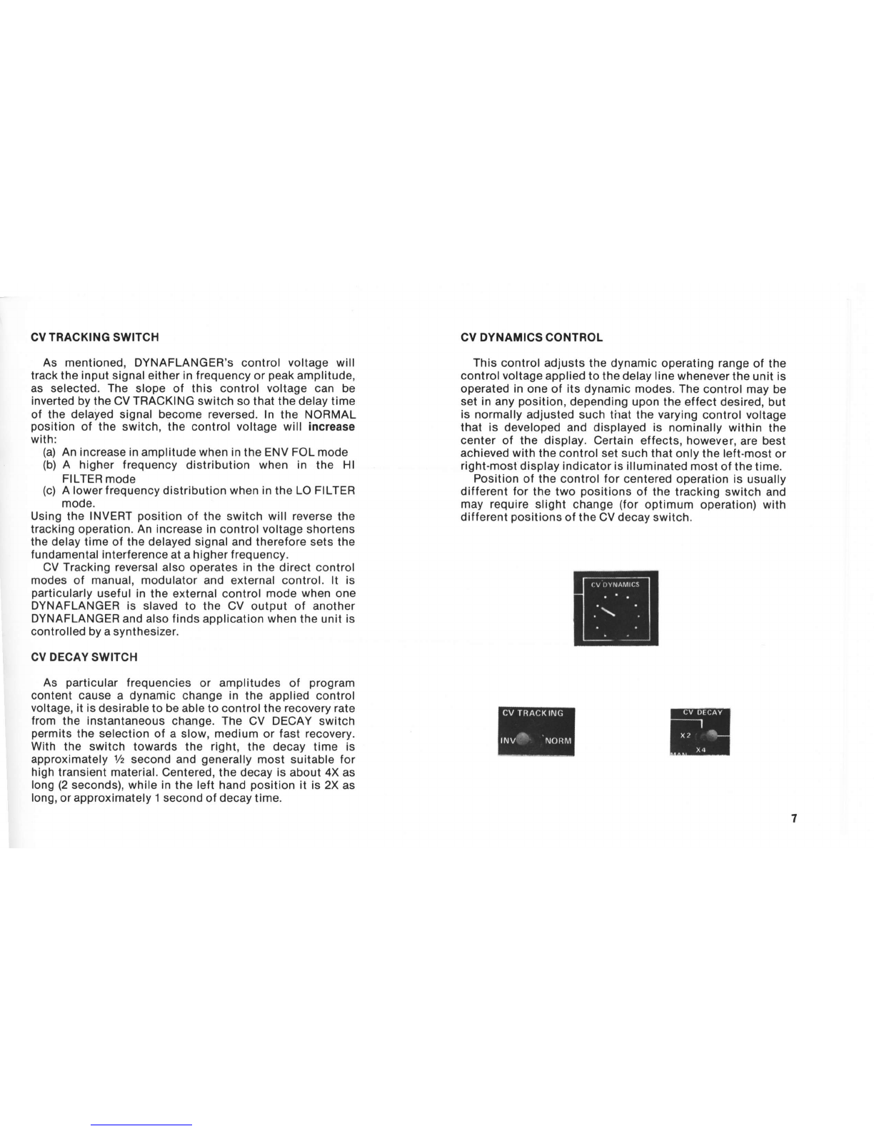
CVTRACKINGSWITCH
As mentioned,DYNAFLANGER's
control
voltagewill
tracklhe
input
signaleitherin
f
requencyor
peak
amplitude,
as selected.The slope
of this controlvoltagecan be
invertedby
theCV
TRACKING
switchsothatthe
delay
time
of thedelayedsignalbecomereversed.In the NORMAL
position
of the switch,the control
voltage
will increase
with:
(a)
An
increaseinamplitudewhenin
the
ENVFOLmode
(b)
A higherfrequency
distribution
when in the Hl
FILTER
mode
(c)
Alowerfrequencydistributionwhenin
the
LOFILTER
mode.
UsingtheINVERT
position
of theswitchwillreverse
the
trackingoperation.
Anincreasein
control
voltage
shortens
thedelaytimeofthedelayedsignalandthereforesetsthe
fundamentalinterferenceatahigherfrequency.
CVTrackingreversalalso
operates
inthe
directcontrol
modesof manual,modulator
andexternalcontrol.lt is
particularly
usefulintheexternalcontrol
modewhenone
DYNAFLANGERis slaved
to the CV outputof another
DYNAFLANGERandalsofindsapplicationwhen
theunit
is
controlledbyasynthesizer.
CVDECAY
SWITCH
As particular
frequencies
or amplitudes
of program
contentcause
a dynamicchange
in the appliedcontrol
voltage,itis
desirabletobeabletocontroltherecoveryrate
from
the instantaneous
change.TheCV DECAYswitch
permits
theselectionof a slow,medium
orfastrecovery.
With the switchtowardsthe right,the decaytime is
approximately
y2
secondand
generally
most
suitable
for
high
transientmaterial.Centered,thedecayisabout4Xas
long
(2
seconds),whilein
the
lefthand
position
it is2X
as
long,orapproximately1second
of
decay
time.
CVDYNAMICSCONTROL
This
controladiusts
thedynamicoperatingrange
otthe
control
voltage
appliedtothedelaylinewhenever
theunitis
operaiedinone
of itsdynamicmodes.
Thecontrol
maybe
set
in
any
position,
dependingupon
theeffectdesired,but
isnormally
adjustedsuchthatthe
varying
controlvoltage
that is developedanddisplayedis nominallywithin
the
centerof the display.Certainetfects,however,
are
best
achievedwiththe
controlsetsuchthatonlytheleft-most
or
right-mostdisplayindicator
is
illuminated
most
ofthetime.
Position
ofthecontrol
tor
centered
operationisusually
different
for
thetwopositions
of thetrackingswitchand
mayrequireslight
change
(foroptimum
operation)with
different
positions
oftheCVdecayswitch.

CVDISPLAY
Therectangularled'sdisplaythe appliedcontrolvoltage
andresultant
delaytimeofthedelayedsignal.
When
theleft
handledis illuminated,thecontrolvoltageis low,thedelay
time is long and the resultant fundamental interference
fiequencyislow.When
theright
hand
ledisilluminated,the
oppositeoccurs.
The display is designed
such that, at the mid-pointof
controlvoltage,none
of the led'sareilluminated.This
point
is used
for calibration,but should be recognizedas it will
occurundernormaloperation,
particularly
manual.
MANUALCONTROL
lnthemanualmode,thedelaytimeofthedelayedsignal
is
determinedbythe
position
ofthiscontrol.
Themodulator
controls,theCVdynamicscontrol
and
the
CVdecayswitch
arenot
operative
in
this
mode,butCVtrackingreversalmay
be utilizedto reversethe slopeof the appliedcontrol
voltage.
MODULATORCONTROLS
When MODULATOR
is selected on the push-button
switch,
the
operatorcan
vary
theRATE
and
DEPTH
at
which
the controlvoltageis appliedto the delayline signal.As
previously mentioned, the depth (delay time) can be
adjusted from 6.4 ms (anti-clockwise
rotation, tracking
normal)to 0.26ms (clockwise
rotation.)Trackinginversion
will reversethese relationships.
The amount of depth
selected
can then be swept automatically
with the RATE
control at ratesbetween0.25and
4 Hz.
FLANGEPHASE
POLARITY
Whenthis control
is in anti-clockwise
rotationfrom
center
position,
polarity
is called
positive(+), and
the
resultant
outputof the
unitisa seriesol notchesor nulls
beginningatapproximately
150Hz
(with
minimumcontrol
voltage
applied).
In
clockwise
rotationtowardthenegative
(-) polarity
markingthe panel,
the resultantoutput
is a
seriesof reinforcementsbeginningat 150 Hz, with
cancellationoccuringat
frequenciesbelowthat.
)
I
J
I
)
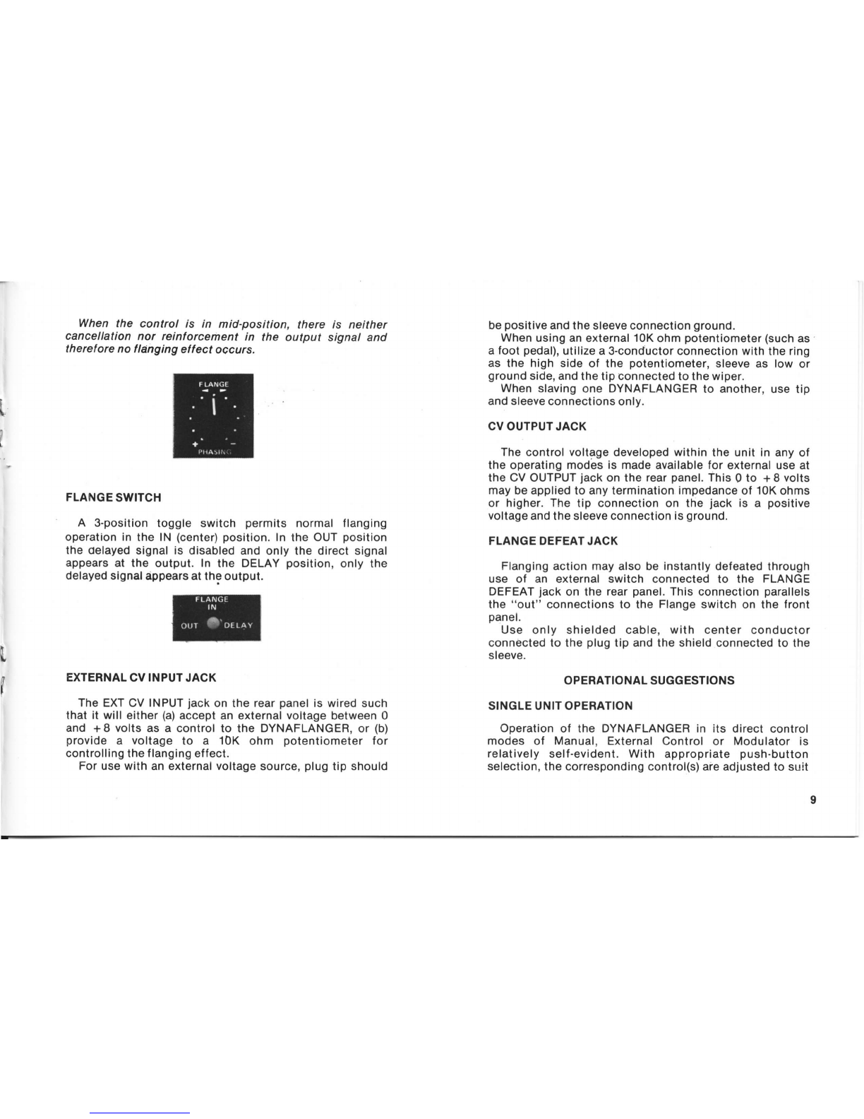
Whenthe control is in mid-position, there
cancellation
nor reinlorcementin the output
therefore
notlanging
eltectoccurs.
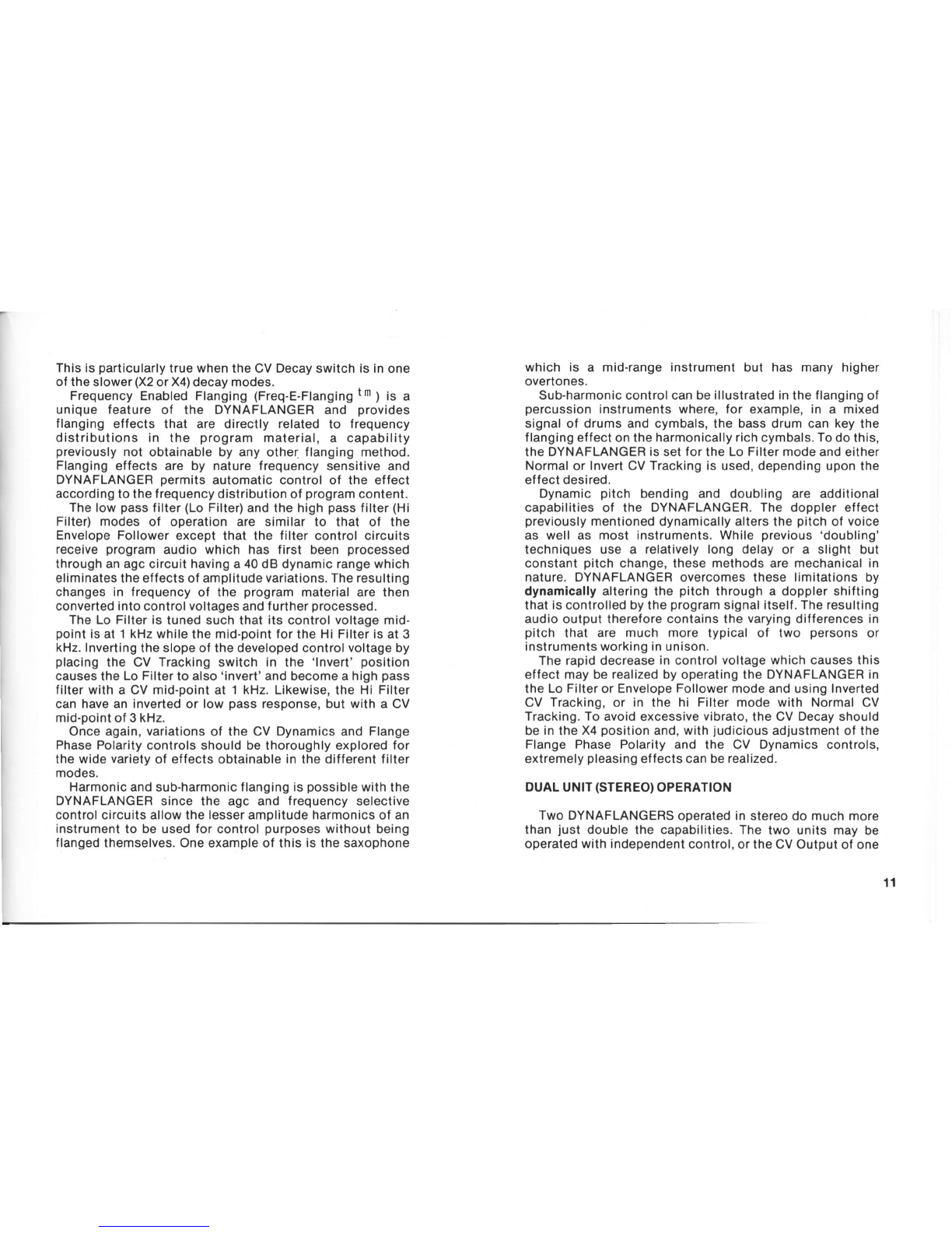
Tru
FLANGE
SWITCH
A 3-position toggle switch permits normal flanging
operationin the lN (center)position.In the OUT position
the oelayed
signal is disabled
and only the direct signal
appears
at the output. In the DELAYposition, only the
delayedsignal
appearsat
theoutput.
EXTERNAL
CVINPUTJACK
The EXT
CV INPUT
jackon the rear
panel
is wiredsuch
that it will either
(a)
acceptan externalvoltagebetween0
and +8 volts as a control to the DYNAFLANGER,
or (b)
provide a voltage to a 10K ohm potentiometer for
controllingtheflangingeffect.
Forusewith an external
voltage
source,
plugtip should
be
positive
andthesleeveconnection
ground.
When
usinganexternal10K
ohm potentiometer
(such
as
a foot pedal),
utilizea 3-conductorconnectionwith thering
as the high side of the potentiometer,
sleeveas low or
ground
side,andthetipconnected
tothe
wiper.
When slavingone DYNAFLANGER
to another,
use tip
andsleeveconnections
only.
CVOUTPUTJACK
The control voltage
developedwithin the unit in any of
the operating
modesis made
available
for externaluseat
the GVOUTPUT
jackon the rear
panel.
This0 to + 8 volts
maybeappliedto anyterminationimpedance
of 10K
ohms
or higher.The tip connection on the jack is a positive
voltage
andthesleeveconnectionis
ground.
FLANGEDEFEATJACK
Flangingaclion mayalso be instantly
defeatedthrough
use of an external switch connected to the FLANGE
DEFEAT
jack on the rearpanel.
This connection
parallels
the "out" connections
to the Flangeswitch on the front
panet.
Use only shielded cable, with center conductor
connectedto the plugtip and the shieldconnected
to the
sleeve.
OPERATIONALSUGG
ESTIONS
SINGLEUNITOPERATION
Operaiionof the DYNAFLANGERin its direct control
modes of Manual, ExternalControl or Modulator is
relatively self
-evident. With appropriate push.button
selection,
the correspondingcontrol(s)areadlusted
to suit
is neither
signal and
I
\
I
ll
L
tl
I

theoperator
for
the
program
materialbeing
processed.
Flange
phasepolarity
maybevariedfromfull
positive
(
+
)
throughthemid-positionnull
to fullnegative
(-) inany
direct
or dynamiccontrolmodewith readilynoticeable
affect.
Dynamic
operation
is controlled
by program
contentin
accordance
withooerator-establishedlimits
anddesires.
Hands-on
experience
is best in learning
what control
settingsare
most
applicablefor
particular
typesof
material.
The
followingtherefore
provides
anexplanation
ofhow
the
DYNAFLANGERfunctionsin its dynamicmodesand
suggests
a few
of themany
possible
set-upsandcontrol
settingsfor
particular
effects.
There
are threebasicmodesof dynamicoperation:
EnvelopeFollower,LowPassFilterandHighPassFilter.
Distinctvariations
for eachof thesebasicmodesare
possible
byuse
of the
2-positionCVTrackingswitchand
the3-positionCV
Decayswitch.Inaddition,theadiustment
capabilitiesoftheCV
Dynamics
control
permits
analmost
infinite
variation
ofthedynamicef
fect.
TheEnvelopeFollower
mode
description
will illustrate
DYNAFLANGERcontrolcapabilities.Incoming
program
audio
is appliedto a peak
detectorwhichestablishesa
control
voltage
proportional
to the instantaneous
peak
amplitude
ofthe
signal.Peaklevelcontrolisusedbecause
it provides
the f
ast dynamicchanges
necessaryf
or
effective
flangin!,whilethe selectableCV decayrate
allowstheoperatorto adjustthis
forthe
various
typesof
program
material.
Shorterdecayratesaremostusefulonpercussion
type
instruments,while
the
longer
(X2
or
X4)decaysareusually
moresuitableonpitch-sensitive
type
instrumentssuchas
acoustic
piano
oracoustic
guitar.
The
fast
decaycan
result
in
adoppler
shiftwhichisveryusableandwillbedescribed
later,but excessiveapplicationon pitch-sensitive
instrumentswoulCnormallybeavoided.
10
As notedearlier,the dynamiccontrolvoltagedeveloped
by the DYNAFLANGER
in the EnvelopeFollowermode is
proportional
to the peak programsignal amplitude,
with
maximum
conlrol
voltagenormallyoccuringat the point
of
maximum amplitude. The CV Tracking switch allows a
reversal in the slope of this control voltage so. that
maximum GV can equal either the highest tundamental
f
langing frequency ('Normal' position) or the lowest
fundamentalflangingfrequency
('lnvert'position).
Notethat DYNAFLANGER'senvelopefollowermodeisa
true following or proporlional system, with attack and
decay of the control voltagebasicallydetermined
by the
program
content itself and not merely
gated on at some
adjustablethreshold
point.
Theamountof controlvoltagedevelopedin the dynamic
modes of envelope
follower,high filter and low filter is
basicallydeterminedby the CV Dynamics
control setting.
The function of this control is somewhat similar to the
depth control of the modulatorsection in that it sets the
range in which the delay line operates under dynamic
conditions.As a result,adjustment
of the CV Dynamics
control can permit only very slight changes in the
differencebetweenthe direct
anddelayedsignalsfor very
subtle or doubling effects,or it can permit wide-ranging
differencesfordramaticorhardflanging
effects.
The CV Dynamicscontrol adjustmentsshould be given
careful attention when first using the DYNAFLANGER
(along
with FlangePhasePolaritysettings)or many
of the
unit's capabilitiesmay initially be overlooked.
In some
instances,it will be found most desireableto set the CV
Dynamicssuchthat the displayedcontrol
voltage
tendsto
becentered
between
the four ledindicators,while in other
applicationsthebest
effect
is
obtained
withasetting
which
ooeratesthe CV indicatorsmoretowardoneendof the led
group or even at one end where there is no apparent
variationin control
voltagebeingapplied
to the delayline.
Thisisparticularly
true
when
theCVDecay
switchis inone
of theslower(X2or X4l
decaymodes.
FrequencyEnabled
Flanging
(Freq-E-Flanging
lm
1
is a
unique feature of the DYNAFLANGERand provides
flanging effects that are directly related to frequency
distributionsin the program material,
a capability
previously
not obtainableby any other flanging method.
Flangingeffects are by nature frequency sensilive and
DYNAFLANGER
permits automatic control of the effect
according
tothe
frequency
distributionof program
content.
Thelowpass
filter
(LoFilter)and the high pass
filter
(Hi
Filter) modes of operation are similar to that of the
EnvelopeFollowerexcept that the filter control circuits
receiveprogram audio which has first been processed
throughanagccircuithavinga 40dB dynamicrangewhich
eliminatestheeffectsofamplitude
variations.
Theresulting
changesin frequencyof lhe program materialare then
converted
into
controlvoltagesandfurther
processed.
The Lo Filteris tunedsuchthat its controlvoltagemid-
ooint
isat 1kHzwhile
the
mid-oointfor
the
HiFilter
isat 3
kHz.Inverting
theslopeof thedevelopedcontrol
voltage
by
placing
the CV Trackingswitch in the 'lnvert'
position
causes
theLo Filterto also'invert'and becomea high
pass
filterwith a CV mid-pointat 1 kHz.Likewise,the Hi Filter
can havean inverted
or low passresponse,but with a CV
mid-pointof3kHz.
Onceagain,
variations
of the CV Dynamicsand Flange
PhasePolaritycontrolsshouldbe thoroughly
exploredfor
the widevariety
of effects
obtainable
in the differentfilter
modes.
Harmonic
andsub-harmonic
flanging
is
possible
withthe
DYNAFLANGERsince the agc and frequency
selective
control
circuitsallowthe
lesser
amplilude
harmonics
of an
instrument
to be usedfor control purposes
without being
flangedthemselves.One
exampleof this is the saxophone
which is a mid-rangeinstrumentbut has many higher
overtones.
Sub-harmoniccontrolcanbe
illustrated
intheflangingof
percussioninstrumentswhere, for example,in a mixed
signalof drums and cymbals,
the bassdrum can key the
flangingeffect
onthe
harmonicallyrichcymbals.To
dothis,
the DYNAFLANGERissetfor the LoFiltermodeandeither
Normal
or Invert
CV
Trackingis used,dependinguponthe
effectdesired.
Dynamicpitch bending and doubling are additional
capabilities
of the DYNAFLANGER.The dopplereffect
previously
mentioneddynamicallyaltersthe
pitch
of voice
as well as most instruments.While previous
'doubling'
techniquesuse a relativelylong delay or a slight but
constant pitch change,
these methodsare mechanicalin
nature. DYNAFLANGER
overcomesthese limitations by
dynamicallyalteringthe pitch
througha dopplershifting
thatiscontrolledbythe
program
signalitself.Theresulting
audiooutput thereforecontainsthe varying
differencesin
pitch that are much more typical of two persons or
instrumentsworking
in
unison.
Therapiddecrease
in control
voltagewhich causesthis
effect maybe realized
by operatingthe DYNAFLANGERin
the LoFilter
or EnvelopeFollowermodeand
using
Inverted
CV Tracking,
or in the hi Filtermode with NormalCV
Tracking.To avoidexcessive
vibrato,
the CV Decayshould
be
in
the
X4
position
and,with
judicious
adjustmentof the
Flange Phase Polarity and the CV Dynamics controls,
extremely
pleasing
effectscanbe
realized.
DUALUNIT
(STEREO)
OPERATION
Two DYNAFLANGERS
operated
in stereodo muchmore
than just doublethe capabilities.The two units may be
operated
withindependent
control,
ortheCVOutput
of one

maybe usedto controlthe otherthrough its CV External
Inputin
a
slavedmode.
Witha pair
of units,
it ispossible
to createanessentially
time-delayed
panning flange effect in which the stereo
image
is dynamically
shiftedwith respect
to frequencyor
amplitude.
Far
superiorto asimpletappeddelay
linestereo
effect,
dualDYNAFLANGERoperation
provides
a dynamic
time differential
of up to 12 milliseconds,
causingthe
apparent
imageto shift in both left and right as well as
inwardandoutwarddirections,
a feature
not possible
with
other audio processing equipment. This wide range of
effects capability in stereo operation is easily
accomplishedbyusing
eitherdifferentoperating
modes
for
thetwo units,
differentialCVTracking,or by offsetting
the
CVDynamicscontrolsand eventhe Flange
PhasePolarity
controls. Using offsets in the controls, a pair of
DYNAFLANGERScanalsoserveas a very
effective
stereo
generator
for
amonauralsignal.
It isfurther
possible
to operatetwo DYNAFLANGERS
in
parallel
to achievea veryinterestingeffect similarto tape
flanging.While
present
technology,
whetherit beanalogor
digital,cannot
produce
delays
inasingleunit
whichclosely
approachzero,it is possible
to use two DYNAFLANGER
unitsto produce
atimedifJerential
of zero.Extremely
short
differential delay times, when used for flanging, can
produce
effectswhich border
<inthe bizarre.
This type of
effect,termed
"Dynamic
Cross
Flanging
tm," allows
the
fundamentalflanginglrequencyto fall in the upper
ranges
of the audio spectrum and, if the delayed signals are
combined out-of-phase,
a complete cancellationoccurs
whenthedif
ferential
delay
approaches
zero.
Dynamic Cross Flanging requires that the two
DYNAFLANGERSbe operated
in the DELAYONLYoutput
mode and the two outputs then be mixed in a console.
DynamicCrossFlanging
isonlyeffectivewhena monaural
12
source is used to feed both DYNAFLANGERS
and the
following simple procedure will allow this complete
dynamiccancellation
tooccur.
Input a common program signal to both
DYNAFLANGERSand adjust the operating levels
accordingly.SettheFlangeswitchto'Delay'onbothunits.
Setthe FlangePhasePolaritycontrolto fullpositive
(+ )
on
oneunitand
full negative
(-) on theother.Connecteach
DYNAFLANGERoutput to a separateconsoleinput and
assigneachof these channels
to a common bus.Set the
console EQcontrols to flat and adjustthe fader
and gain
trimcontrols
for
equal
amplitude.
Select the manual operatingmode on both units and
adjust the Manual
control on each to the control voltage
mid-pointwhereall CV Rangeindicatorsareextinguished.
Adjustthe
gain
trimon oneof thechannelsuntilcomplete
cancellationoccurs. lt may also be necessaryto very
slightlyadjustthedelaytime
(Manual
control)ofoneunitto
achievefull cancellation.
Theflange
notchdepth is nowat
its maximumandanyfurtherlevelchangesshouldnow be
madeat the sendcontrolof the source
goingto the DYNA-
FLANGERStoavoidimbalance.
With the flangenotch established,a numberof effects
are possible. Dynamic Cross Flanging occurs with one
DYNAFLANGERbeing
keptin
the
Manual
modewitha
fixed
delay
time
whilethedelaytime
of
the
other
unitismovingin
relation to it. The zero crossover point is basically
controlled by the position of the Manualcontrol on the
'fixed' unit and may be moved at will. The other
DYNAFLANGERmay be operated in any of its modes,
provided
the Flange
PhasePolaritycontrol remainsin its
initial
position.
lt isalso
possible
to operatebothunitsin
the dynamic, independent
or slavedmodes to provide
a
totallydynamiccontrolledzerocrossover
point which is a
f
unction of frequency, amplitude, or external control

voltage,
dependinguponthe selectedoperating
modes
of
thetwounits.
'Farout' specialeffects are also possible
by operating
two
DYNAFLANGERSin
either
aseries
or
parallel
operation
to further accent the flanging effect. Paralleloperation
allows both units to flange independently
and, when
combined,athird
flangeeffectis
createdbythedif
lerential
time delaybetweenthe unitsas well as from theirown
independentdelays.Seriesoperation
of the two units
resultsinaflangeeffectfromonethatisthenre-flangedby
thesecond.
The ExternalCV Inputnot only allowsslavingof one
DYNAFLANGERto another,but permits synthesizer
interfaceandkeyingcontrolof theflangingeffect,withthe
DYNAFLANGERtrackingswept
f
ilters,ADSR
(attack-decay-
suslain-release)controls and keyboardcontrol voltages.
Note
thatthemaximumexternalcontrolvoltageshould
not
exceed+ 8 voltsd-c.Certainsynthesizers
or other
voltage
sourcesmayhavea higher
outputcapabilityand,
if this
is
the case,a voltage
dividershouldbe utilizedto limit
the
maximuminout
tothe
DYNAFLANGER
to +8volts.
TheExternalCVInput
jack
also
provides
avoltageat the
ringterminalsothatasimple
foot
pedalpotentiometer
can
control the flanging
effect. Informationregarding
connectionsto such a control have been mentioned
previously.
DYNAFLANGER'sCVOutput
voltage
canalsobeusedto
controlasynthesizer
orany
olher
voltage
controllable
(0
to
+ 8 vdc
or less)
device
in relation
to the program
material
thatisbeing
processed
bytheDYNAFLANGER.
From this somewhat lengthy but actually
brief
description
of DYNAFLANGER
capabilities,
it becomes
obviousthat you have
one of the most versatile
effects
devicesavailable,onethatcanaccent
practically
anytype
ol programmaterialin a very subtle or a very dramatic
manner.
MAINTENANCE& REPAIR
Your DYNAFLANGER
does not requireany periodic
maintenanceoradiustment.
All MICMIX
products
arecoveredby a LimitedWarranty
anddetails
of your DYNAFLANGERwarranty
areprovided
below. For warranty service outside the United States,
contacl
your
nearestMICMIX
dealer.
DYNAFLANGER,while
usingstandardtypecomponents,
contains sophisticatedcircuitryand certain internal
adjustmentsare critical to the achievement
of its
perf
ormance
characteristics.
Under no circumstancesshould
any arbitrary"tweaking" be per-
lormed
oninternalcontrols.
Re-calbration
ol a DYNAFLANGER
following certain
typesot repairrequiresspecializedequipmentin orderto
provideoriginal performance
characleristcs.Contact the
Customer
ServiceDepartment
attheFactory
or,outsidethe
UnitedStates,
your
nearestMICMIX
dealer
for information
regardingrepair
of
your
DYNAFLANGER.
A complete
Maintenance
& Calibration
Manual
maybe
purchased
fromthe Factory.
ContacttheCustomerService
Department.
13

LIMITEDWARRANTY
MICMIXAudio Products,Inc. warrants
this product
againstdefectsinmaterials
and
workmanship
undernormal
usageand service
for a periodof one year from date of
delivery
totheoriginal
purchaser.
Any
defective
product
will berepaired,
or replaced
atour
option, without charge if the producl is returned
transportation
prepaid
tothe FactoryServiceDepartment
at
theaddresslistedbelow.A packing
slipshouldaccompany
allshipmentsandincludethesender'snameandaddress,
date
of
purchase,
and
information
describinganydefect.
This warrantydoes not cover damagesresulting from
transportation,accident, alteration,misuse or abuse,
incorrectwiring
by others,or failure
to followoperating
instructions,
nor does the warrantycoverthe cost of any
inconvenience
or any direct, indirect
or consequential
damageby reason
of the fact that such productwas non-
conforming
or
defeclive.
Theforegoingwarrantyis in lieuof all other warranties,
expressed,written or implied, including any warranty
of
merchantability
or fitnessfor purpose,
and
MICMIXAudio
Products,Inc.
neitherassumesnor authorizesany other
persons
to assumefor it anyother
liability
in connection
with
thesaleofits
products.
REPAIRSORALTERATIONSPERFORMED
BY
UNAUTHORIZED
PERSONN
EL
VOIDSTHE
GUARANTEE
MICMIX
Audio
Products,
Inc.
2995
Ladybird
Lane
Dallas,
Texas
75220
14

FTTEI
2995 Ladyblrd
MICMIXAudio
Products,
Inc.
Dallas,TX 75220
Table of contents
Other MicMix Audio Recording Equipment manuals


