BIO-MED DEVICES MVP-10 User manual

BIO-MED DEVICES
MVP-10
NEONATAL/PEDIATRIC
VENTILATOR
INSTRUCTION MANUAL
Catalog #2050
Rev. 042916
BIO-MED DEVICES INC.
61 SOUNDVIEW ROAD, GUILFORD, CT 06437
(800) 224-6633 FAX 203-458-0440
www.biomeddevices.com


TABLE OF CONTENTS
Addendum 1
MAGNETIC RESONANCE IMAGING ENVIRONMENT 1
SYMBOL EXPLANATION 2
UNPACKING 2
STANDARD MVP-10 2
MVP-10 MRI COMPLETE PACKAGE 2
WARRANTY 4
WARNINGS 5
CAUTIONS 6
I. GENERAL 7
A. INTENDED USE 7
B. MODES OF OPERATION 7
C. FEATURES 7
D. PERFORMANCE CHARACTERISTICS 8
II. DESCRIPTION 9
A. PRINCIPLES OF OPERATION 9
B. CONTROLS, INDICATORS, AND CONNECTIONS 12
C. SPECIFICATIONS 12
III. INSTALLATION CONSIDERATIONS 15
A. EQUIPMENT REQUIRED 15
B. SUPPLY GAS 15
C. MOUNTING BRACKET 15
D. PATIENT CIRCUIT 15
E. OPTIONAL EQUIPMENT 15
IV. VENTILATOR SET-UP 17
A. CONNECTION OF GAS SUPPLY 17
B. CONNECTION OF PATIENT CIRCUIT 17
V. SELECTION OF VENTILATION PARAMETERS AND ADJUSTMENT
OF CONTROLS 19
A. TIME-CYCLED OPERATION 19
B. NON-CYCLED OPERATION 23
VI. PRECAUTIONS 30
VII. MAINTENANCE 32
A. NORMAL CARE 32
B. CHECKOUT PROCEDURE 32
C. CALIBRATION 34
D. IF SERVICE IS REQUIRED 35
APPENDIX A 36
AUTHORIZED REPRESENTATIVE IN THE EUROPEAN COMMUNITY 36
APPENDIX B 37
MVP-10 VENTILATOR MR INFORMATION 37

1
Addendum
MAGNETIC RESONANCE IMAGING ENVIRONMENT
WARNING: ONLY AN MVP-10/MRI ORIGINALLY MANUFACTURED BY BIO-MED
DEVICESFORMRIUSEORRECEIVINGANMRICONVERSIONBYBIO-MEDDEVICES
IS TO BE USED IN AN MRIENVIRONMENT. THESE UNITS WILLBEFREE-STANDING
AND DESIGNATED BY AN MR-CONDITIONAL LABEL AND AN “M” AS A SUFFIX TO
THE SERIAL NUMBER.
WHEN USING THE MVP-10/MRI VENTILATOR IN AN MRI ENVIRONMENT, THE
FOLLOWING PRECAUTIONS MUST BE TAKEN:
THE VENTILATOR MUST NOT BE PLACED INSIDE THE MRI BORE (SEE
APPENDIX B).
DONOTUSEANYACCESSORIES,INCLUDINGOXYGENANDAIRCYLINDERS,
REGULATORS, MOUNTING BRACKETS AND SUPPORT STANDS, THAT ARE
MADE OF ANY METAL THAT COULD BE ATTRACTED BY A MAGNET.
2
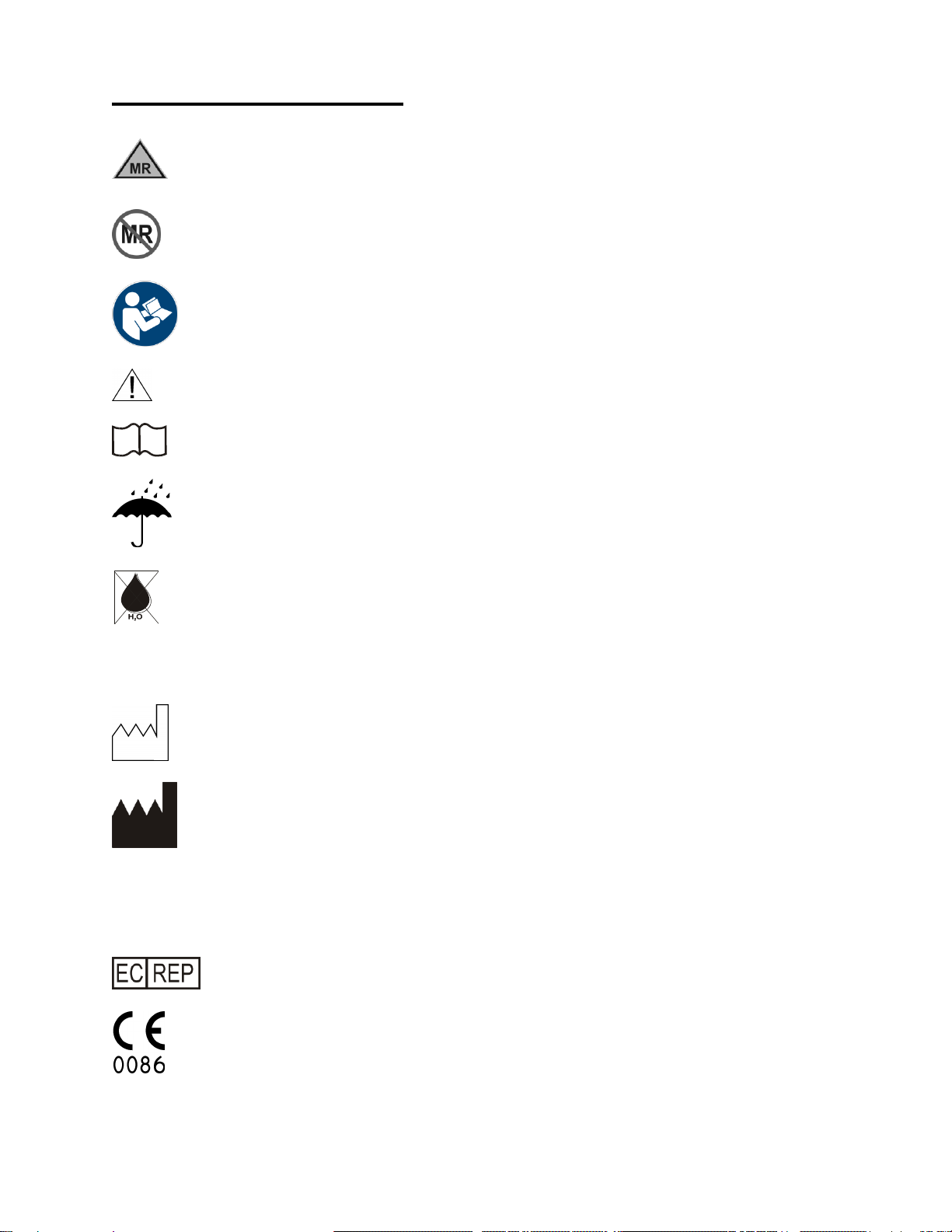
SYMBOL EXPLANATION
MR Conditional
MR Unsafe
Follow Instructions for Use
Caution: Consult accompanying documents
i
Consult Instructions for Use
Product should be kept dry
Warning: Condensed water in air supply can cause malfunction of this device
Rx Only
Caution: Federal law restricts this device to sale by or on the order of a licensed
healthcare practitioner.
Date of Manufacture
Manufacturer
SN
Serial Number
REF
Catalog Number
Authorized Representative in the European Community.
The CE mark displayed on this product signifies that this device is in compliance with the
European Medical Devices Directive (Council Directive 93/42/EEC). As a prerequisite for
the CE mark, Bio-Med Devices operates under an ISO 13485 compliant quality system
(covering the design and manufacture of medical devices). The four-digit code underlying
the CE mark (0086) pertains to Bio-Med's Notified Body, the British Standards Institute,
whose function is to investigate and attest to the validity of CE-mark claims.

3

2
UNPACKING
When received, the instrument should be immediately unpacked and checked to see that
all component parts have been received, and that there is no apparent damage.
If the MVP-10 was shipped directly to you, and damage due to shipmentisfound, notifythe
carrier at once. Only you, the consignee, canmake a claim against the carrier for damage
in shipment.
If you received the equipment from a BMD dealer, return it to him for adjustment.
The following items are shipped as part of the MVP-10 equipment. Check to assure that all
items have been received.
STANDARD MVP-10
MVP-10 Ventilator
Two (2) Patient Circuits, Catalog #2030
Two (2) supply hoses (1/4" ID x 3/8" OD x 10' long) with attached DISS fittings; one
hose for air and one for oxygen.
Bracket (for mounting MVP-10 to column)
Instruction Manual and Warranty Card
Infant Test Lung
MVP-10 MRI COMPLETE PACKAGE
Note: All components are MR-conditional.
MVP-10 MRI Ventilator
Two (2) Patient Circuits, Catalog #2030
Two (2) supply hoses (1/4" ID x 3/8" OD x 10' long) with attached DISS fittings; one
hose for air and one for oxygen.
Heavy Duty MRI Stand
Low Flow Air/O2 MRI Blender
Blender Bracket for 2” pole
Blender Hose Kit (air/O2 supply wye & coupler & 2’ supply hose)
2’ O2 Supply Hose
2’ Air Supply Hose
Cylinder Brackets (upper and lower)
Deluxe MRI O2 E-cylinder Regulator
Deluxe MRI Air E-cylinder Regulator
Instruction Manual and Warranty Card
Infant Test Lung
See the next page for instructions on assembling this package.

3
MVP-10 COMPLETE PACKAGE SETUP INSTRUCTIONS
1. If not already done, assemble the stand per the instructions that came with it.
2. If not already done, install the patient connector (white nylon barb) into the brass tee on the back of the ventilator
per the instruction that came with the barb.
3. With the tilt bracket that is on top of the stand facing you, insertan O2cylinder into therings to the right and an air
cylinder into the rings to the left. If necessary, loosen the locking knob and adjust the upper set of rings higher or
lower to properly support the cylinders. It should be approximately in the position shown above.
4. Install the green, O2regulator onto the O2 cylinder and the yellow air regulator onto the air cylinder. Before finally
tightening the regulators on each cylinder, rotate the regulator body so the pressure gauge window is facing up
and the 50 PSI OUT fitting is facing front as shown above. Rotate the cylinders in their brackets so the regulators
are in the final, desired orientation and tighten the two thumbscrews against the cylinders to hold them in place.
5. Place the ventilator into the tilt bracket at the top of the stand. Its angle may be adjusted, if desired, by loosening
the two front screws on top of the stand, adjusting the bracket and then retightening the two screws.
6. Remove the two screws holding the two halves of the blender bracket togetherand separatethetwo halves. Wrap
the two halves around the pole and loosely secure the bracket to the pole below the ventilator using the two
screws. Be sure the two pins in the bracket are towards the bottom so the blender does not fall through the
bracket when installed. Hold the blenderup in front of, but not engaged with the bracket to aidin where you want
the final position of the bracket and blender to be. Once this is determined, secure the bracket in place by
alternately tightening one screw and then the othersowhendone, theyhavebeenequallytightened, evidencedby
somewhat equal gaps between the front and back halves.
7. Place the blender in the bracket. You may have to temporarily remove the ventilator from its bracket to do this.
8. Install the male-to-male coupler into the O2supply fitting on the bottom of the blender. To this coupler, connect
one end of a 2’ O2 supply hose and then connect the other end to the OUT fitting on the O2 regulator.
9. Connect one end of the 2’ air supply hose to the air input on the blender and then connect the other end to the
OUT fitting on the air regulator.
10. Connect the air/ O2wye to one end of the remaining 2’ supply hose. Connect the wye to the air and O2inputs on
the back of the ventilator and the remaining end of the 2’ hose to the fitting on the left side of the blender as
viewed from the front.
11. The two 10’ supply hoses may be connected to their respective regulator input fittings labeled “50 PSIIN”. These
then are used to connect to air and O2wall sources.

4
WARRANTY
The Model MVP-10 Neonatal Pediatric Ventilator is warranted to be free from defects in
workmanship and material for one (1) year from the date of purchase. To insure that its
performance is maintained, any necessary repair during the warranty period must be
performed by BMD or an authorized agent.
The warranty does not apply to the patient circuit and hoses supplied with the instrument.
Nor does the warranty cover abuse or misuse of the instrument, or damage due to
unauthorized servicing.
If service is required, theinstrumentmust be properlypackedand shipped pre-paid,directly
or through your dealer, to: Bio-Med Devices, Inc.
61 Soundview Road
Guilford, CT 06437
An explanation of the problem should accompany the equipment. Please include your
name and telephone number in the paperwork.
There is no oral orimplied warranty of the instrument'sfitnessfora particularpurpose other
than its intended use.

5
WARNINGS
Whenever the MVP10 is connected to a patient, a skilled operator should be present at all
times at the ventilator or within visual or hearing range of the alarm system used with the
MVP10.
High oxygen concentrations may be hazardous to the patient.
If the gas supplyfails, the patient may breathe atmospheric gas through the failsafe valve.
This is only a temporaryemergencymeasure, whichrequireselevated inspiratoryeffort and
should be corrected immediately.
A patient filter should always be used in the patient breathing circuit to prevent cross
contamination. Breathing through the negative pressure relief valve in a contaminated
environment can be hazardous.
Extreme care should be taken to assure that the patient circuit components are connected
correctly. Improper connection can cause malfunction.
A test lung should be ventilated prior to each use to ensure that all modes are functioning
correctly. An external spirometer should be used to verify correct volumes and flow rates.
Always be certain that the PIP Limit is set correctly and is operative even when volume
limiting, to prevent possibleinadvertent administrationof high pressure.Increasedpressure
can be caused by blocked tubes, changes in patient compliance or resistance, or system
malfunction.
Breathing through the negative pressure relief valve requires a greatly increased work of
breathing and only air isprovided. A situation in which the patient is breathing through this
valve should be rectified immediately in order to prevent possible adverse affects to the
patient.
Clean, dry, regulated gas supplies at 50 5 PSI (345 ±34.5 kPa) must be used at all times
or malfunction may result. Note carefully that the logic (power) gassupplyshould be100%
oxygen at all times to give the greatest accuracy of the control settings and to assure the
most trouble-free operation.
If the ventilator is to beused unattended or without remote monitoring, a high/low pressure
alarm must be used at all times with the user within visual and/or audible range of this
alarm.
A TWO-WAY SAFETY RELIEF VALVE is installed internally. This valve opens when
pressure in the hose delivering gas to the patientrisesabove 70cmH2O10cmH2Oorfalls
below -4 cmH2O. Its purpose is to limit maximum circuit pressure and to allow patient
inspiration in the unlikely event of failure of the gas supply. It is meant to allow
spontaneous breathing for a short time only until the operator can respond to the
disconnect alarm and rectify the supply malfunction. In such a situation, its use in a
contaminated environmentcouldbehazardous. TheSAFETYRELIEFVALVEmustnotbe
removed; and must be maintained with its screened port up and unobstructed.

6
Any HUMIDIFIER used with the MVP-10 must be a "flow-through" type having a low
pressure drop. Use of a humidifier with a "bubbler" tube or pressure jet will render the
SAFETY RELIEF VALVE ineffective.
Do not use in an MRIroom unless the MVP-10 has beenbuilt by Bio-Med Devices for such
an environment. This will be indicated by an MR-conditional label on top of the unit and an
“M” at the end of the serial number.
Do not re-use disposable breathing circuits. Re-use of disposable (single-use) breathing
circuits can result in contamination (patient infection) or circuit degradation (circuit can fall
apart, develop holes, or exhibit polymer decay).
A high / low pressure alarm monitor must be used in conjunction with this ventilator. The
high pressure alarm level should never be set above the lowest relief valve setting.
Do not continue using a ventilator which has been significantly impacted or abused.
Volume-limited ventilators should not be used on unattended patients.
CAUTIONS
The BMD MVP-10 Ventilator is intended for use by qualified clinical personnel only. This
Instruction Manual should be read before using the equipment.
Because this is a CE marked device, it must never be modified without prior expressed
written consent from Bio-Med Devices.
As noted later in the text of this Manual, the MVP-10's time cycle settings are affected by
large changes in barometric pressure, flow rates, and gas composition. They are
repeatable, however, within 5% underconstant conditions. As with any ventilator, periodic
blood gas studies should be made to ensure proper levels of ventilation.
Antistatic or electrically conductive hoses or tubing should not be used.

7
I. GENERAL
A. INTENDED USE
The model MVP-10 Ventilator is for respiratory support of neonatal and pediatric
patients both in hospital and during transport. It is intended primarily for use in all
applications requiring tidal volumes in the range up to 660 milliliters. It may be used
with a wide range of I/E ratios, including inspiratory time greater than expiratory
time.
WARNING: Do not use in an MRI room unless the MVP-10 has been built by Bio-
Med Devices for such an environment. This will be indicated by an MR-conditional
plaque on top of the unit and an “M” at the end of the serial number.
B. MODES OF OPERATION
It is a continuousflow Ventilator which may beused in any of thefollowing operation
modes:
Time cycled, with volume or pressure limitation, with or without Positive End
Expiratory Pressure (PEEP).
-Intermittent Positive Pressure Ventilation (IPPV).
-Intermittent Mandatory Ventilation (IMV).
Continuous Positive Airway Pressure (CPAP).
Continuous Oxygen Administration (COAD) or constant flow.
C. FEATURES
Portable: compact and light weight
May be hand carried or attached to incubator; used without interruption
during transportation; compatible with masks, tents,and endotrachealtubes.
Gas Powered: portable pressurized tank or wall outlet, providing 50 PSI
oxygen or air.
Operable in Hazardous Areas: non-electric, no shock hazard, case
constantly self-purged.
High Reliability: controlled by miniature pneumatic logic elements; fail-safe
maximum pressure limits; negligible frictional wear.
Very low compliance and dead space factors.
Prevention of CO2 build-up by constant flow wash-out.
Readily usable with standard accessory humidifier, oxygen blender, oxygen
analyzer and pressure alarms.

8
D. PERFORMANCE CHARACTERISTICS
Direct control is provided for inspiratory and expiratory times, air and oxygen flow
rates, and maximum pressure and PEEP or CPAP levels within the patient circuit.
Oxygen concentration, respiratory rate, tidal volume, and I/E ratio may also be
controlled.
Oxygen concentration…………... variable, 21% to 100%
Respiratory rate…………………. variable, 0 to 120 breaths/min.
Tidal volume……………………… variable, 0 to over 660 ml.
I/E ratio…………………………… variable
Oxygen concentration is determined by the air and oxygen flow rates indicated by
two front panel meters. Flow rates correspondingto adesired oxygenconcentration
can be determined by use of CHART A. At extremely low flow rates accuracy may
be reduced; for more accuratedetermination an auxiliaryoxygen analyzer shouldbe
used.
Respiratory rate and I/E ratio are determined byINSP. TIME andEXP.TIMEcontrol
settings. These settings are approximate time reference points which are
repeatable within 5%.* For greater accuracy, an external monitoring device maybe
used.
The tidal volume, when operated in a time-cycled mode is the product of total flow
and inspiratory time:
TIDAL VOLUME (ml) = TOTAL FLOW RATE (ml/sec) X INSPIRATORYTIME (sec)
NOTE: Flow rate is not Minute Volume
MINUTE VOLUME = TIDAL VOLUME X RESP. RATE
It should be noted that the PIP and PEEP/CPAP control settings are affected by
flow. When flow is increased, the pressure levels set by these controlswill increase
somewhat. These changes may be noted on the pressure gauge and the settings
readjusted.
*At elevations above sea level, the intervals set by the INSP. TIME and EXP. TIME controls are increased due to lower
barometric pressure. The difference is about 2½% per 1000' of elevation. With an air supply connected to the POWER
OXYGEN inlet fitting, the time intervals are about 10% less than with pure oxygen connected.

9
II. DESCRIPTION
A. PRINCIPLES OF OPERATION
The MVP-10 Ventilator provides continuous flow that may be time-cycled for
automatic ventilation with either volume or pressure limits, and with or without
Positive End Expiratory Pressure (PEEP). It may also be used without time cycling
to provide continuous flow past the patient at ambient pressure, e.g. Continuous
Oxygen Administration (COAD), or at a positive pressure, e.g. Continuous Positive
Airway Pressure (CPAP).
1. Time-Cycled Modes:
A constant flow is provided past the patientWYE. The expiration valve is cycled so
that it is closedfor a pre-set time, (TI) and opened for a pre-set time, (TE). When it is
opened, gas flows past theWYE at ambient pressure and is vented to atmosphere;
when closed, exhaust to atmosphere is prevented and pressure builds upwithin the
circuit, delivering gas to the patient. Gas flow into the system isessentially constant
since the source pressure (50 PSI) is much greater than the maximum possible
circuit pressure (80 cm H2O, or 1.1 PSI). An example of this use is for
administration of Intermittent Positive Pressure Ventilation (IPPV).
a. Volume-limited:
The pressure developed in the patient's airway depends upon the total
system-patient compliance and the tidal volume being administered. When
the PIP control is set at a pressure above the pressure developed in the
circuit, then the automatic ventilation is volume limited, andaconstantflowis
delivered to the patient. In this condition the tidal volume (Vt) is the product
of the total flow rate (VI) and inspiratory time (TI):
Vt = TI x VI
andminute volume (V) is the product of tidal volume and respiratory rate (f):
V = Vt x f
Should the patient compliance become less or resistance increase, then the
developed pressure could increase up to the PIP setting. At that point, the pressure
in the patient circuit becomes limited and constant. Tidal volume is no longer
delivered to the patient; excess gas is vented to atmosphere.
b. Pressure-limited:
With flow rate and inspiratory time set, the pressure developed in the
patient's airway depends upon the system and patient compliances. This
pressure is limited by the setting of the PIP control. While the expiration
valve is closed, pressure within the circuit builds up to the PIP setting. Atthat
point, the valve acts to allow flow past the WYE to atmosphere, while
maintaining the airway pressure at the PIP setting. During the expiratory
time, the valve is opened.

10
c. Intermittent Mandatory Ventilation (IMV):
Respiratory rate is set to allow one or more voluntary breaths between
machine-controlledbreaths. Withsufficientflow,thepatient'sminutevolume
and the voluntary tidal volumes are not necessarily limited by the machine
parameters. The respiratory rate may be set to support the patient, but less
than the anticipated voluntary respiration rate. The lower respiratory rate is
normally set by increasing the Expiratory Time.
d. Positive End Expiratory Pressure (PEEP):
By use of the PEEP/CPAP control, a pressure may be maintained in the
patient's airway during the expiratory time in any of the above time-cycled
modes (i.e. PEEP), or during a non-cycled mode with continuous flow-past
the patient (i.e. CPAP).
Adjustment of this control places a controlled pressure on the diaphragm of
the expiration valve maintaining the patient circuit at this pressure during the
expiratory time.
2. Non-Cycled Modes:
A constant flow is provided past the patient WYE, without cycling the expiration
valve.
a. Continuous Positive Airway Pressure (CPAP):
A pre-set pressure is maintained across the expiration valve. Continuous
flow is provided past the patient WYE, allowing the patient to inhale from this
flow while maintaining the airway at the pre-set constant positive pressure.
b. Continuous Flow, or Constant Oxygen Administration (COAD):
No pressure is maintained across the open expiration valve (PEEP/CPAP
control fully clockwise), and a continuous flow is provided past the patient
WYE, allowing the patient to inhale from the flow at ambient pressure.
Figure 2 is a flow diagram showing the interconnections within the MVP-10.
The expiration valve is controlled by a pneumatic logic circuit which is
comprised of four (4) (early models had three (3)) miniature diaphragm
devices, four (4) adjustable valves, several fixed flow resistances and aflow
accumulator. The diaphragm device is a gas actuated, double-piloted,
spring-offset, three- way valve. The entire logic circuit is isolated from the
patient circuit by the diaphragm of the expiration valve. Gas flowing into the
logic circuit cannot enter the patient circuit, and the exhalation gas cannot
enter the logic circuit.
A 40-micron filter is incorporated in the input of the logic circuit. The
pneumatic switching elements have a rated life of over one-billion switching
operations, at rated supply pressure.
The logic circuit controls the two time intervals for inspiration and expiration
and controls the pressure in the patient circuit.

11
FIGURE 2 - FLOW DIAGRAM
GAS
SUPPLIES
50 PSI
AIR
FITTING
O2
FITTING
AIR FLOW
CONTROL
O2 FLOW
CONTROL
PRESSURE GAUGE
PNEUMATIC LOGIC
CIRCUIT
CYCLE/CPAP
SWITCH
PEEP/CPAP
CONTROL
EXP TIME
CONTROL
MAX PRESSURE
CONTROL
INSP TIME
CONTROL
EXPIRATION VALVE
CONNECTION
GAUGE CONNECTION
PATIENT CONNECTION
ADJUSTABLE
RELIEF VALVE
TWO-WAY
RELIEF VALVE HUMIDIFIER
(OPTIONAL)
PRESSURE ALARM
(OPTIONAL)
WYE
PATIENT
AIRWAY
EXPIRATION
VALVE
EXHAUST
MVP - 10 PATIENT CIRCUIT

12
B. CONTROLS, INDICATORS, AND CONNECTIONS
CONTROLS (Front Panel)
(1) CYCLE/CPAP Switch: Selects non-cycling (CPAP) or time-cycled
(CYCLE) modes of operation.
(2) PEEP/CPAP Control: Sets PEEP level when CYCLE/CPAP switch isset
to CYCLE, or CPAP level when set to CPAP.
(3) EXP. TIME Control: Sets expiratory time in time- cycled modes.
Calibrated in seconds from 0.25 to 2.5 (May be set to 30 seconds forIMV).
(4) INSP. TIME Control: Sets inspiratory time in time- cycled modes.
Calibrated in seconds from 0.2 to 2.0.
(5) PIP Control: Sets maximum pressure limit in patient circuit. Used to
establish a pressure- limited mode.
(6) LPM OXYGEN Control: Sets flow rate of oxygen.
(7) LPM AIR Control: Sets flow rate of air.
INDICATORS (Front Panel)
(8) PRESSURE Gauge: Indicates proximal airway pressure (in cm H2O).
(9) OXYGENFlowmeter: Indicatesoxygenflowintosystem(inliters/minute).
(10) AIR Flowmeter: Indicates airflow into system (in liters/minute).
CONNECTIONS (Rear Panel)
(11) AIR: Connection to pressurized source of clean, dry, oil-free air (50±5
PSI). Mates with female DISS air fitting.
(12) POWER OXYGEN: Connection to pressurized source of 100% Oxygen,
medical grade (50±5 PSI, 345 ±34.5 kPa). When only one gas supply is
used, it must always be connected to POWER OXYGEN connector, since
only this line supplies the logic circuit. This mates with female DISS
oxygen fitting.
(13) GAUGE: Connection to patient WYE (for measurement of pressure in
patient circuit). Connect 1/8" ID tubing.
(14) PATIENT: ConnectiontopatientcircuitatADJUSTABLERELIEFVALVE
and through HUMIDIFIER (if used).
(15) EXP. VALVE: Connection to expiration valve (for control of time-cycling,
and CPAP or PEEP or PIP). Connect 1/8" ID tubing.
CAUTION: Antistatic or electrically conductive hoses or tubing should not be
used.
NOTE: Filtered and dried, regulated gas supplies must be used to ensure
reliable operation.
C. SPECIFICATIONS
Gas Supplies:
Air: Clean, dry, oil-free, 50 5 PSI (345 ±34.5 kPa) pressure
Oxygen: Clean, dry, medical grade, 50 5 PSI (345 ±34.5 kPa) pressure

13
Inspiratory Time: variable 0.2 to 2.0 seconds calibrated*
Expiratory Time: variable 0.25 to 2.5 seconds calibrated*; (Variable to 30 seconds,
uncalibrated)
I/E Ratio: variable 0.2 / 30 to 2.0 / 0.25 (equals 1/150 to 8/1)
Oxygen Flow Rate: variable 0 to 10.0 liters/minute meter calibration accuracy: 3%
full scale
Air Flow Rate: variable 0 to 10.0 liters/minute, meter calibration accuracy: 3% full
scale
Max. Pressure Setting: variable up to 70 10 cm H2O
Pressure Gauge: -20 to +120 cm H20; 3% full-scale accuracy (at ATPD- ambient
temperature & pressure dry)
Fail-Safe Pressure Limitations:
TWO-WAYSAFETYRELIEFVALVE(installedinternally):opensatpressuresabove
70 10 cm H2O or below –4 1 cm H2O
ADJUSTABLE RELIEF VALVE (installed at PATIENT connection): user adjustable
to open between a maximum pressure of 80 cm H2O 10 cmH2O when turned fully
clockwise to a minimum of 10 cmH2O 5 cmH2O when turned fully
counterclockwise.
PEEP/CPAP Range: variable up to 18 3 cm H2O at flow of 6
liters/minute
Breathing Circuit Insp Resistance: 0.03 cm H2O / lpm, at 5 lpm flow(model 2030)
Breathing Circuit Exp Resistance: 0.06 cm H2O / lpm, at 5 lpm flow (model 2030)
Dead Space: 0.5 ml maximum
Consumption of gas by Logic Circuits: approximately 4 liters/minute at 50 breaths
per minute
Weight: 2.3 kg. (5 lbs. 2 oz.)
Physical Dimensions: 20 x 23 x 7.4 cm (8 x 9 x 3 in.)
Storage Temperature: 32° to 122°F (0°to 50°C)
Operating Temperature: 14° to 122°F (-10°to 50°C)
NOTE: Two safety valves are provided to protect the patient from:
asphyxiation due to failure, disconnection or depletion of the gas supply
excessive pressure due to blockage or failureof theexpiration valveor hose.

14
The TWO-WAY SAFETY RELIEF VALVE is installed internally. It vents pressures
above 70 cm H2O 10 cm H2O. It also opens at negative pressures below -4 cm
H2O to allow patient inspiration. (If protection at a lower negative pressure is
desired, another more sensitive valve should be added.)
The ADJUSTABLE RELIEF VALVE is installed externally and may be adjusted to
vent pressures between 70 cm H2O 10 cmH2O and 10 cm H2O 5 cmH2O.
*INSP. TIME and EXP. TIME control settings are calibrated at sea level and 20o
C., ATPD, using USP oxygen. Large changes of barometric pressure or altitude
changes, or use of diluted oxygen will affect time calibration; hence, the settings
should be regarded as reference points rather than precise time indicators.
However, time settings are repeatable within 5%. Approach time settings in a
clockwise direction.

15
III. INSTALLATION CONSIDERATIONS
A. EQUIPMENT REQUIRED
All equipment required for use of the MVP-10 has been supplied with the
instrument, except for the gas supply. No special tools are needed.
It will be convenient to have available a test lung when setting the
ventilator parameters before connecting to a patient. If Bio-Med Devices
Infant Test Lung (BMD #1021) is not available, a simple finger cot may be
attached to the patient WYE or the WYE may be occluded.
B. SUPPLY GAS
The supply gas isnormally a pressurized tank(s) or wall source of medical
or therapy grade oxygen and/or air. The pressurized tanksshouldbefitted
with regulators adjusted to 50 5 PSI (345 ±34.5 kPa).
No flow restrictingdevice (e.g. flowmeter, throttling valve) can be placed in
the supply line. A flow restricting device interferes with the operation of
the pneumatic logic and may render the time-cycling inoperative.
The MVP-10 will operate with a supply pressure outside of the 50 5 PSI
(345 ±34.5 kPa) range, but accuracy of settings may be impaired. In no
case should a supplypressure less than 35 PSI (242 kPa) or over 100 PSI
(690 kPa) be connected to the MVP-10 as it will cause malfunction of the
ventilator.
The operating time that may be expected from common tank sizes with
different flow rates is given in Table B.
C. MOUNTING BRACKET
The supplied mounting bracket may be installed on a column.
D. PATIENT CIRCUIT
The patient circuit supplied with the MVP-10 incorporates approximate
3-foot lengths of tubing between the MVP-10 and (1) thepatientWYE and
(2) the expiration valve.
WARNING: Always use a bacterial filter.
WARNING: Do not re-use disposable breathing circuits
E. OPTIONAL EQUIPMENT
Other standard equipment which may be used with the MVP-10 at the
option of the user include:
Oxygen Blender --connected in the supply line to the POWER OXYGEN
connection,orbothPOWEROXYGENandAIRconnectorsusingBMD"Y"
Table of contents
Other BIO-MED DEVICES Medical Equipment manuals


Popular Medical Equipment manuals by other brands


cetoni
cetoni BASE 120 quick start guide

LABORIE
LABORIE Solar Blue Service & installation manual

Hitachi
Hitachi S3ESEL instruction manual

Centre Light Solutions
Centre Light Solutions Strialite 1011 Instructions for use

Bestcare
Bestcare 33232 manual

Graham Field
Graham Field Hausted HSS500 Operation instructions


