BIO-MED DEVICES IC-2A User manual

BIO-MED DEVICES
IC-2A
ADULT INTENSIVE CARE VENTILATOR
SERVICE MANUAL
CATALOG #8011A
PRICE $35.00
REV. 122606
BIO-MED DEVICES, INC.
61 SOUNDVIEW ROAD, GUILFORD, CT 06437 (203) 458-0202
www.biomeddevices.com

TABLE OF CONTENTS
WARRANTY ................................................................................................................... 1
WARNING, CAUTIONS, AND NOTES ........................................................................... 3
WARNINGS................................................................................................................. 3
CAUTIONS .................................................................................................................. 4
NOTES ........................................................................................................................ 4
I. DESCRIPTION......................................................................................................... 8
INTRODUCING THE IC-2A VENTILATOR.................................................................. 8
Controls, Indicators and Connectors............................................................................ 8
Modes of Operation ..................................................................................................... 9
SPECIFICATIONS AND LIMITATIONS....................................................................... 9
II. FUNCTIONAL DESCRIPTION .............................................................................. 11
OPERATING MODES ............................................................................................... 11
LOGIC GATE............................................................................................................. 15
III. INSTALLATION AND OPERATION .................................................................. 17
INSTALLATION ......................................................................................................... 17
IC-2A VENTILATOR SET-UP.................................................................................... 19
IC-2A FINAL CHECKOUT ......................................................................................... 19
OPERATING PROCEDURE...................................................................................... 23
IV. MAINTENANCE INSTRUCTIONS ..................................................................... 29
GENERAL MAINTENANCE ...................................................................................... 29
PREVENTIVE MAINTENANCE................................................................................. 29
V. TESTING AND CALIBRATION ............................................................................. 31
INITIAL LOGIC PRESSURE TESTS ......................................................................... 31
FAIL-SAFE CUTOFF VALVE CALIBRATION............................................................ 32
DEMAND CIRCUIT CALIBRATION........................................................................... 33
MAXIMUM PRESSURE CALIBRATION.................................................................... 35
PEEP/CPAP CALIBRATION ..................................................................................... 36
TIMING CALIBRATION ............................................................................................. 37
FLOW RATE CALIBRATION..................................................................................... 38
PRESSURE GAUGE CALIBRATION ........................................................................ 39
VI. PARTS LISTS .................................................................................................... 40

1
WARRANTY
BIO-MED DEVICES, INC. expressly warrants to the PURCHASER, this Ventilator to be
free from defects in material and workmanship for a period of one (1) year from the date
of purchase. BIO-MED DEVICES, INC. will repair or, at its option, replace any part or
all of this Ventilator which fails to conform to this warranty at no cost to the purchaser
FOR MATERIALS AND LABOR. The warranty does not apply to the patient circuit and
hoses supplied with the instrument nor does the warranty cover abuse or misuse of the
instrument, or damage due to unauthorized servicing.
BIO-MED DEVICES, INC. will pay any shipping charges required in repairing or
replacing any part or all of this Ventilator within three (3) months from the date of
purchase. Thereafter, shipping charges will be paid by the PURCHASER.
THIS WARRANTY IS EXPRESSLY MADE IN LIEU OF THE WARRANTIES OF
MERCHANTABILITY AND FITNESS FOR A PARTICULAR PURPOSE AND ALL
OTHER WARRANTIES EXPRESSED OR IMPLIED.
This warranty shall become null and void if the Ventilator is opened, otherwise tampered
with, or if repairs are attempted by the PURCHASER, or if the Ventilator is operated by
anyone other than trained and duly qualified medical personnel, or if the “Warranty
Registration Card” is not returned within four (4) weeks of the date of purchase to:
BIO- MED DEVICES, INC.
61 Soundview Road
Guilford, CT 06473
Tel: (203) 458-0202
Fax: (203) 458-0440

2
HOW TO USE THIS MANUAL
This manual is intended to provide an easily useable source of reference that will assist
you in operating and maintaining the BIO-MED DEVICES’ IC-2A Ventilator. This
manual is configured in six sections, each of which will support a general understanding
of the IC-2A Ventilator and provide specific maintenance and service instructions. A
complete Table of Contents, List of Illustrations, and List of Tables are included to help
you locate any item of information or procedure in the manual.

3
WARNING, CAUTIONS AND NOTES
SAFETY PRECAUTIONS
This system presents no hazardous when operated properly. However, the following
safety rules should be observed when operating the system:
• Read this manual carefully and follow all recommended procedures.
• Always turn off the equipment prior to performing any maintenance.
FOR YOUR INFORMATION
WARNING - Signifies a procedure or condition that could cause bodily injury if
performed improperly.
CAUTION- Signifies a procedure or condition that could damage the equipment if
performed improperly.
NOTE- Signifies a procedure or condition that requires your special attention.
WARNINGS
• No flow-restricting device (e.g., flowmeter, throttling valve) should be placed in
the supply line. A flow-restricting device interferes with the operation of the
pneumatic logic and may render the time cycling inoperative which can endanger
the health of the patient.
• In no case should a supply pressure less than 35 or over 80 psi be connected to
the IC-2A Ventilator as it will cause malfunction of the ventilator which will
endanger the health of the patient.
• To ensure the health of the patient, pressure alarms must always be used
whenever the IC-2A Ventilator is used unattended.
• No device should ever be connected to the exhalation valve line. Malfunction
may result which could endanger the health of the patient.
• The supplies must be regulated 50 psi sources without flow restricting devices
(e.g., flowmeter, needle valve, etc.). This ensures proper operation and safety of
the patient.
• Whenever the IC-2A Ventilator is turned off, disconnect the patient before turning
the Ventilator back on, in order to avoid erroneous breaths and possible harm to
the patient.
• It is essential, with the triggered demand flow of the IC-2A, that the inspiratory
effort be properly adjusted to assure that the patient can obtain gas.
• Bio-Med Devices cannot be held responsible for any failure to adhere to the
recommendations set forth in this manual.
• Because this is a CE marked device, it must never be modified without prior
expressed written consent from Bio-Med Devices.

4
CAUTIONS
• Hose fittings should be hand-tightened to avoid damage to fittings.
• The gas supply should be clean and dry.
• Never connect a water supply to these fittings.
• Do not attempt to repair the demand valve. Its assembly is highly critical and
must be performed at the factory.
NOTES
• In the SIMV mode, it is essential that the INSPIRATORY EFFORT control be set
so that the patient can trigger the machine at all times.
• The pressurized tanks should be fitted with regulators adjusted to 50 ±5 psi.
• Any intensive care ventilator circuit may be used with the IC-2A Ventilator
including a configuration using both inspiratory and expiratory hoses. Any
exhalation valve may be used. It should be noted that the IC-2A is supplied with
a patient circuit (part number 8002A). The maximum pressure limit and
maximum PEEP pressure are calibrated using this exhalation valve. If another
valve is used, there may be a difference in the maximum pressure limit and
maximum PEEP pressure attainable, depending on the area ratios of the
exhalation valve used.
• The IC-2A Ventilator does not have an internal oxygen blender.
• During IPPV an assist control breath will cause response of both the CYCLE and
DEMAND indicators. A control cycle will activate only the CYCLE indicator.
• In the SIMV mode, it is unnecessary to add an external constant flow source due
to the triggered demand flow system. It is necessary, however, that the
INSPIRATORY EFFORT control be properly adjusted at all times to assure
proper operation.
• The MAX. PRESSURE control must be turned off (fully clockwise) in the CPAP
mode.
• Do not over-tighten the supply fittings with a wrench, as they could be damaged.
• Do not use the logic supply regulator to decrease the logic supply pressure.
Auto-cycling is not to be confused with the regular timed cycling controlled by the
inspiratory and expiratory settings. Auto-cycling can be detected by a very short
or non-existent expiratory time and also by the activation of the DEMAND
indicator at the beginning of an inspiratory cycle without a vacuum being applied
to the patient circuit.

5
FIG. 1-1 IC-2A Ventilator

6
BIO−MED DEVICES, INC.
GAUGE
PRESSUREMAX. PRESSURE
PATIENT
HOSE
GUILFORD, CT U.S.A.
100% O
EXHALATION
2
VALVE
SUPPLY
PATIENT GAS
SUPPLY
LOGIC GAS
CAUTION:
THE CIRCUIT WILL NOT
PRESSURIZE WITH THIS
KNOB AT THE FULL CW
POSITION.
50±5 PSI
345±34.5 kPa
30 LPM MAX. FLOW 82 LPM MAX. FLOW
345±34.5 kPa
50±5 PSI
AIR/OXYGEN
WARNING:
CLEAN, DRY 50±5 PSI REGULATED SOURCES OF MEDICAL GRADE OXYGEN & AIR
MUST BE USED OR MALFUNCTION CAN RESULT. OXYGEN CONCENTRATION OF
POWER SUPPLY GAS AND/OR ALTITUDE AFFECT TIMING ACCURACY. CONSU LT
THE INSTRUCTION MANUAL FOR CORRECTION FACTORS.
CAUTION:
FEDERAL LAW RESTRICTS THIS DEVICE TO SALE BY OR ON THE ORDER OF A
PHYSICIAN.
BEFORE OPERATING THIS INSTRUMENT, READ THE INSTRUCTION
MANUAL THOROUGHLY. PARTICULAR ATTENTION SHO ULD BE GIVEN
TO THE USE OF THE DEMAND MODE.
REF
SN
DATE OF MFR.
I
N
C
R
E
A
S
E
!
0086
FIG. 1-2 IC-2A Ventilator (Rear View)
7
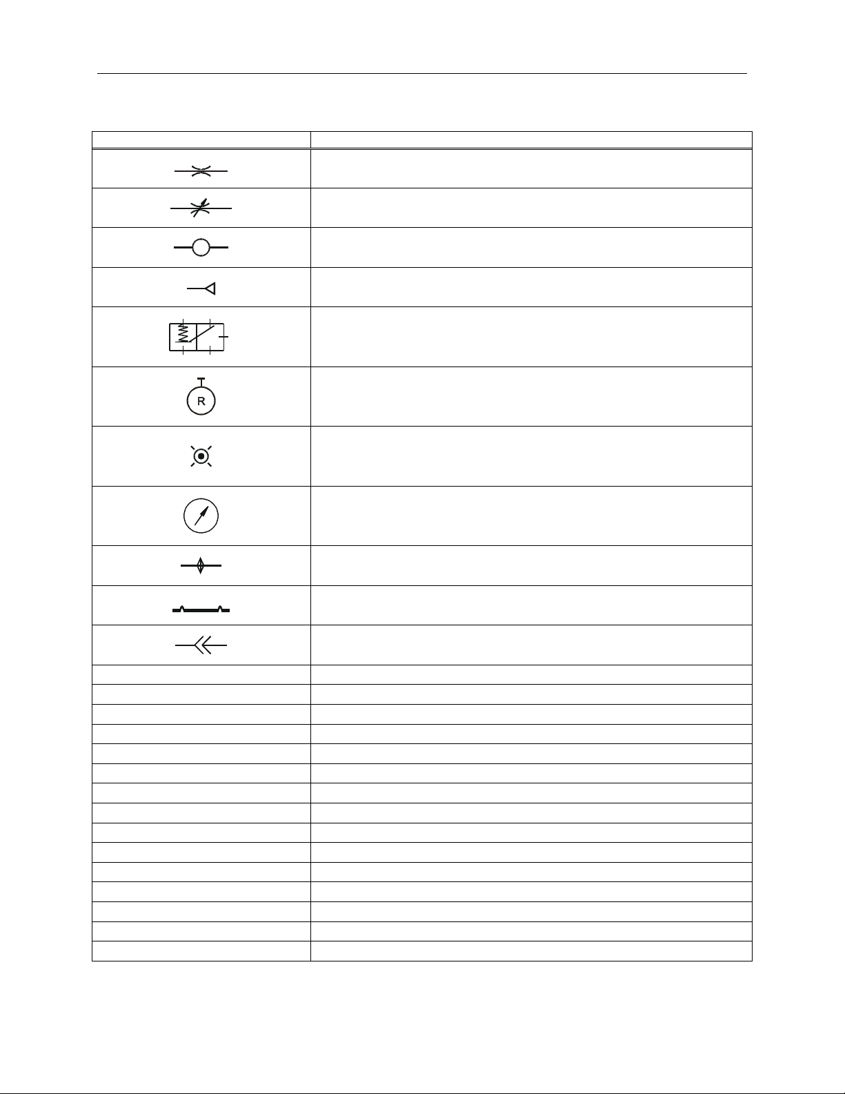
SYMBOLS AND ABBREVIATIONS
Special symbols and abbreviations are used in this manual and are listed here to
provide an easy reference for maintenance personnel.
SYMBOL/ABBREVIATION DEFINITION
Orifice, Resistor, or Restrictor
Variable Orifice, Variable Resistor, Variable Restrictor, or
Needle Valve
Volume Capacitor
Regulated Gas Supply
13
5
42
Logic Gate
Pressure Regulator
Indicator
Pressure Gauge
Filter
Diaphragm
Removable Connector
BK Black
BL Blue
BN Brown
CL Clear
GR Green
OR Orange
RD Red
VI Violet
WH White
YL Yellow
CPAP Continuous Positive Airway Pressure
IMV Intermittent Mandatory Ventilation
IPPV Intermittent Positive Pressure Ventilation
PEEP Positive End Expiratory Pressure
SIMV Synchronized Intermittent Mandatory Ventilation

8
I. DESCRIPTION
INTRODUCING THE IC-2A VENTILATOR
The IC-2A Ventilator (Figure 1-1) is a highly sophisticated, precision, pneumatic, life
support device, built to rigid specifications.
The IC-2A Ventilator is designed for respiratory support of adult patients both in a
health-care facility and during transport. It can be operated within volume or pressure
limits and has a wide range of inspiratory/expiratory time ratios (I/E). Its compact
lightweight design permits hand-carrying or attachment to a stand thus facilitating
uninterrupted support during transport.
The IC-2A Ventilator is compatible with masks and endotracheal and tracheotomy
tubes. It is gas-powered using either a portable pressurized tank or wall outlet providing
50 psi oxygen or air. It is non-electric, presents no shock hazard and features a
constantly self-purging case. Miniature pneumatic logic control elements produce high
reliability due to negligible frictional wear. The IC-2A Ventilator is compatible with
standard accessories: humidifier, oxygen blender, oxygen analyzer, pressure alarm
and patient circuit.
Controls, Indicators and Connectors
a. Front Panel – Table 1-1 lists the IC-2A Ventilator front panel controls and
indicators and their functions. Refer to Figure 1-1.
b. Top and Back Panel Controls and Connectors – Table 1-2 lists the IC-2A
Ventilator top and back panel controls and connectors and their functions.
Refer to Figure 1-2.
Table 1-1. IC-2A Ventilator Front Panel Controls and Indicators
Control or Indicator Function
CYCLE/MANUAL CPAP switch Two-position toggle switch for selecting non-cycling
(Manual CPAP) or time-cycled (CYCLE) modes of
operation
INSPIRATORY TIME control Rotary control for setting inspiratory time in time-
cycled modes; calibrated from .4 to 2 seconds.
EXPIRATORY TIME control Rotary control for setting expiratory time in time-
cycled modes; calibrated from .5 to 4 seconds and
may be set to 45 seconds or more in IMV range.
FLOW RATE control Rotary control for setting flow rate; calibrated from
20 to 75 lpm.
INSPIRATORY EFFORT control Rotary control for adjusting patient trigger
sensitivity
PEEP/CPAP control Rotary control for setting PEEP level when
CYCLE/MANUAL CPAP switch is set to CYCLE or
for setting CPAP level when CYCLE/MANUAL
CPAP switch is set to MANUAL CPAP

9
NORMAL/SIMV switch Two-position toggle switch for selecting normal
time-cycled mode (NORMAL) or SIMV mode
(SIMV)
OFF/ON switch Rotary switch for controlling main power to the
fluidic logic
MANUAL button Momentary action push button for manually
controlling inspirations
Pressure Gauge Analog gauge indicates proximal airway pressure;
calibrated from –10 to +120 cmH20
CYCLE indicator Activates to indicate any time-cycled inspiratory
period
DEMAND indicator Activates to indicate any cycle initiated by patient
breathing effort or backup timer
Table 1-2. IC-2A Ventilator – Top and Back Panel Controls and Connectors
Control or Indicator Function
Max. Pressure Control Rotary control for setting upper pressure limit for each cycle
Logic Gas Supply
100% O2 connector
A DISS oxygen fitting for connecting to source of clean, dry,
50±5 psi oxygen in order to power logic
PATIENT GAS SUPPLY
Connector
DISS, oxygen fitting for connection to source of clean, dry,
50±5 psi supply of patient breathing gas mixture
PATIENT HOSE
Connector
22mm (15mm inside) connector for attaching main patient
hose
EXHALATION VALVE
Connector
Powers the exhalation valve
PRESSURE GAUGE
Connector
Connects to pressure line T-adapter to provide proximal
airway pressure
Modes of Operation
The IC-2A Ventilator operates in the following modes:
a. Time Cycled, either volume or pressure limited, with or without Positive End
Expiratory Pressure (PEEP).
1. Intermittent Positive Pressure Ventilation (IPPV)
2. Synchronized Intermittent Mandatory Ventilation (SIMV)
b. Continuous Positive Airway Pressure (CPAP)
c. Manual
SPECIFICATIONS AND LIMITATIONS
Table 1-3 lists the specifications and limitations of the IC-2A Ventilator.

10
Table 1-3. IC-2A Specifications and Limitations
Specification/Limitation Range
Logic Oxygen Clean, dry, medical grade 50 ±5 psi oxygen
Patient Supply Clean, dry, oil-free, 50 ±5 psi patient breathing gas
mixture
Inspiratory Time (Calibrated*) 0.4 to 2.0 seconds
Expiratory Time (Calibrated*) 0.5 to 4.0 seconds (variable to 45 seconds or more,
uncalibrated, in the IMV range)
*INSPIRATORY and EXPIRATORY TIME controls are calibrated at sea level and 20°C using USP
oxygen. Changes in barometric pressure, altitude changes, or use of diluted oxygen will affect time
calibration.
Table 1-3. IC-2A Specifications and Limitations (continues)
Specification/Limitation Range
Rate 1-1/3 to 66 bpm
SIMV Backup Rate 4-2/3 to 6-3/4 bpm
I/E Ratio Infinitely Adjustable
Flow Rate (Calibrated) 0 to 75 lpm
Tidal Volume 0 to >3000 ml
PEEP/CPAP 0 to 25 ±5 cmH2O
System Pressure Gauge -10 to +120 cmH2O; ±3% full scale accuracy
Visual Indicators Cycle; Demand
Two-Way Relief Valve Internally installed valve opens above 120 ±20 cmH2O or
below -4±1 cmH2O
Adjustable Maximum
Pressure Valve
0 to 120 cmH2O
Inspiratory Effort
Sensitivity Range
-0.5 to –10.0 cmH2O
Logic Gas Consumption 12 LPM (approx.); varies with control settings; higher
pressure increases consumption
Dimensions 3-3/8” X 6-1/8” X 10-1/4”
(8.57 X 15.56 X 26.14 cm)
Weight 9 lbs approx. (4.1 kg)
Storage Temperature: 32° to 122°F (0°to 50°C)
Operating Temperature: 14° to 122°F (10°to 50°C)

11
II. FUNCTIONAL DESCRIPTION
INTRODUCTION
Figure 2-1 presents a schematic view of the IC-2A Ventilator. Figure 2-2 presents the
logic system. Refer to the list of symbols and abbreviations at the front of the manual.
OPERATING MODES
Intermittent Positive Pressure Ventilation (IPPV)
In the IPPV mode the IC-2A Ventilator acts as a controller or assist/controller. The
following control switch settings are required:
Switch Setting
CYCLE/MANUAL
CPAP
CYCLE
NORMAL/SIMV NORMAL
A pilot valve, operated by the timing signal from the fluid logic, opens for the time set by
the INSPIRATORY TIME control. This allows the gas to flow at a rate set by the FLOW
RATE control. The exhalation valve pressurizes, closing the exhalation port and thus
ensuring that all gas is directed to the patient.
Since the gas supply is a high pressure source and the pressure reached in the patient
is relatively low, the flow rate remains constant and independent of changes in patient
pressure.
a. Volume Limited. The pressure developed in the system depends on the total
compliance and the column of gas delivered. If the adjustable pressure limit
is set higher than the pressure that is reached, then no gas is dumped to
atmosphere and the ventilator is volume limited. In this mode the tidal volume
(VT) is the product of inspiratory time (TI) and flow rate (VI),
VT=TIX VI
In this mode the pressure limit is normally set to 10cm H2O above the pressure attained.
It then acts as an upper-level fail-safe. If patient resistance or compliance causes a
significant increase in pressure, the pressure will be limited at the preset level. When
this occurs the ventilator is no longer volume limited since some gas is dumped to
atmosphere and therefore the tidal volume is unknown.
b. Pressure Limited. Whenever the pressure reached within the patient circuit is
equal to the maximum pressure limit established using the MAX PRESSURE
control on the rear panel, the excess gas is dumped to atmosphere and the
unit is operating in a pressure-limited mode. The Ventilator may be used
continuously in the pressure-limited mode by setting the maximum pressure
and adjusting the inspiratory time and flow rate to give a large enough volume
of gas per breath to ensure that the preset pressure level is reached on each
cycle. When the pressure limit is reached, it is held until the end of
inspiration, thus producing a plateau-type pressure waveform.

12
Fig. 2-1 IC-2A Schematic Diagram
LEGEND
4 Pressure Gauge Line Connector
5 Pressure Gauge
11 Flow Rate Control Valve (panel control)
12 OFF/ON Control Valve (panel control)
13 Patient Hose Connector
15 Logic Gas Supply 100% O2 Connector
16 Exhalation Valve Line Connector
17 Patient Gas Supply Connector
22 Two-way Relief Valve
23 Logic Supply Filter
31 Pilot Line Variable Resistor
32 Pilot Valve
33 Fail-safe Cutoff Valve
35 Patient Supply Regulator
36 Logic Supply Regulator
42 Pressure Gauge Variable resistor
51 Patient Circuit Manifold

13
Fig. 2-2 IC-2A System Logic Diagram
LEGEND
1 CYCLE/MANUAL CPAP Toggle Valve (panel switch)
2 MANUAL Button
3 CYCLE Indicator
4 Inspiratory Time Needle Valve (panel control)
6 Demand Indicator
7 PEEP/CPAP Needle Valve (panel control)
8 NORMAL/SIMV Toggle Valve (panel switch)
9 Expiratory Time Needle Valve (panel control)
10 Demand (inspiratory effort) Valve (panel control)
16 Exhalation Valve Line
19 Max. Pressure Needle Valve (panel control)
24 Inspiratory Time Variable Resistor
25 Expiratory Time Variable Resistor
27 Fail-safe Variable Resistor
28 PEEP/CPAP Variable Resistor
29 Maximum Pressure Variable Resistor
31 Pilot Line Variable Resistor
41 Demand Valve Variable Resistor
43 Inspiratory Time Capacitor
47 Expiratory Time Capacitor
52 Feedback Resistor
53 Backup Timer Variable Resistor
54 Delay Line (with Delay Capacitor)
55 Backup Timer Capacitor

14
The lowest rate attainable in the IPPV mode is established by the backup timer which is
6 breaths/min.
Synchronized Intermittent Mandatory Ventilation (SIMV)
The IC-2A Ventilator provides a unique, triggered, demand-flow system for the addition
of a constant flow source. It eliminates the need for a check valve flowmeter, bag etc.
The EXPIRATORY TIME control is set in the IMV range allowing the patient one or
more spontaneous breaths between the machine assisted breaths.
NOTE: In the SIMV mode it is essential that the INSPIRATORY
EFFORT control be set so that the patient can trigger the machine
at all times.
When the NORMAL/SIMV switch is set, in the SIMV position, while the ventilator cycles
with each inspiratory effort, the pressure builds up in the patient circuit only after the end
of the expiratory time. This is achieved by pressurizing the exhalation valve only after
patient-triggered breath at the end of the expiratory time (assisted breath). At the end of
the expiratory time the machine waits for the next inspiratory effort and, therefore, when
the assisted breath is provided it is synchronized to the patient’s breathing effort. In the
SIMV mode, in the event no patient inspiratory effort is sensed for a period of ten
seconds, a backup time provides a backup breath. Every time an inspiratory effort is
sensed, whether for a spontaneous or an assisted breath, the backup timer is reset.
The interval between assisted breaths may still be set to the maximum expiratory time
of at least 45 seconds.
Each time the machine is cycled it provides gas flow to the patient even when the
exhalation valve is unpressurized. If the inspiratory time and flow rate are set in a way
that provides more gas than needed by the patient, the excess passes to atmosphere.
Should that patient require more gas during a spontaneous breath than is provided, and
if a negative pressure is still being generated (following the termination of the inspiratory
period), another inspiratory period (and as many more as necessary) will be initiated,
thus providing as much gas as required. The patient may exhale at any time during
spontaneous breathing since the exhalation valve is unpressurized. It is, however,
desirable to set the flow rate and inspiratory time to give a tidal volume as close to the
spontaneous tidal volume as possible. With this triggered demand flow system, it is
only necessary to trigger the unit initially. The IC-2A then provides a bolus of gas equal
to the inspiratory time multiplied by the flow rate. Unlike other systems it is not
necessary to maintain a constant negative pressure of several cmH2O during each
spontaneous breath. This eliminates the oscillations observed in other systems at low
flow rates and makes possible the use of normal bubble-type humidifier with the bubbler
in place. Note that during the spontaneous breaths, even though the exhalation valve is
not pressurized, there may be a buildup of 3 to 5 cmH2O pressure depending on flow
rate set. This is due to slight resistance of the exhalation valve at high flow rates.
Positive End Expiratory Pressure (PEEP)
The PEEP/CPAP control applies a constant pressure to the exhalation valve which may
be adjusted to give a pressure in the patient circuit from 0 to 25 cmH2O.

15
The PEEP/CPAP control is operative in all modes of operation, The INSPIRATORY
EFFORT control may be set to compensate for the PEEP/CPAP pressure level in the
patient circuit. Whenever the PEEP/CPAP level is changed, the INSPIRATORY
EFFORT control should be readjusted.
Continuous Positive Airway Pressure (CPAP)
When the CYCLE/MAUAL CPAP switch is placed in the MANUAL CPAP position, the
function of the IC-2A Ventilator is very similar to the SIMV mode. In the CPAP mode,
and inspiratory effort triggers the flow if a volume of gas equal to inspiratory time
multiplied by flow rate. However, in this mode the high pressure is not applied
intermittently to the exhalation valve. Only the PEEP/CPAP control is operative. The
PEEP/CPAP control may be turned fully clockwise thus applying zero pressure to the
exhalation valve. In this way the ventilator may be used to administer, on demand, gas
of a preset oxygen concentration at ambient pressure. In both the SIMV and CPAP
modes there may be a momentary fluctuation of a few cmH2O pressure demanding on
the flow rate, inspiratory time, system compliance, and gauge response.
In this mode, turn the EXPIRATORY TIME control to maximum (fully clockwise) and
place the NORMAL/SIMV switch in the SIMV position. This prevents false cycling and
helps to reduce gas consumption. It is also advisable, for added safety, that the MAX.
PRESSURE control be turned fully clockwise when using the CPAP mode,
Manual Mode
The manual mode can be used for hyperventilating before suctioning, sighing the
patient, or synchronizing with chest compressions for cardiopulmonary resuscitation.
The MANUAL button is inoperative until CYCLE/MANUAL CPAP switch is switched to
the MANUAL CPAP position. The inspiration time is set with the INSPIRATORY TIME
control. Press the MANUAL button long enough to each cycle to set the inspiratory timer
and then release the button. The inspiratory period then lasts as long as the time set
with the INSPIRATORY TIME control. The tidal volume is then equal to the inspiratory
time multiplied by flow rate (volume limited).
If the MANUAL button is held in for a time greater than the preset inspiratory time, then
inspiration lasts during the entire time that the MANUAL button is pressed. In this case
the volume delivered is unknown. The Pressure Gauge may be observed as an
indicator of degree of ventilation. By using the PEEP/CPAP control it is possible to
ventilate manually with PEEP. The MAX. PRESSURE control may also be used in
manual mode to pressure limit each breath.
LOGIC GATE
The Logic Gate contains a floating assembly comprised of two diaphragms connected
by a pair of precision shoulder pins. Switching is accomplished as each diaphragm
covers and uncovers its associated nozzle. This process causes the assembly to move
0.032 inches. There are no sliding parts in the Logic Gate ensuring long life and
trouble-free operation.

16
The five Logic Gate ports are generally used as follows:
Ports 1 and 2 Switching Signals
Port 3 Output Signal
Ports 4 and 5 Supply or Exhaust
Pressure to Ports 1 and 2 actuate a diaphragm assembly allowing either Port 4 or 5 to
connect with Port 3. With no input on either Port 1 or 2, Ports 5 and 3 are
interconnected. An input to Port 1 switches the diaphragm assembly causing Port 5 to
close and Port 4 to open resulting in a connection between Ports 4 and 3. Equal
pressures on both Ports 1 and 2 allow the spring to keep the diaphragm assembly in a
position where Ports 5 and 3 are connected.
Figure 2-3 illustrates the physical aspects of the Logic Gate in a cutaway view and also
provides a functional view.
1534 215
3
4
2
Fig. 2-3 Logic Gate, Cutaway & Schematic Views

17
III. INSTALLATION AND OPERATION
INSTALLATION
Unpacking
When received, the instrument should be immediately unpacked and checked to see
that all component parts have been received, and that there is no apparent damage.
If the IC-2A was shipped directly to you and damage due to shipment is found, notify the
carrier at once. Only you, the consignee, can make a claim against the carrier for
damage in shipment.
If you received the equipment from a Bio-Med Devices dealer, return it to the dealer for
adjustment.
The following items are shipped as part of the IC-2A equipment. Check to assure that
all items have been received.
• IC-2A Intensive Care Ventilator
• 2 complete disposable Patient Circuits, BMD part #8002A
• 1 10 ft. supply hose with female DISS oxygen fittings, BMD #1010
• 1 high pressure oxygen wye, BMD part #8005
• 2 supply elbow adapters; male to female DISS oxygen
• Mounting bracket
• Instruction manual and warranty card
• Test lung, BMD part #1020
Equipment Required
All equipment required for use with the IC-2A Ventilator is supplied with the instrument,
except for the gas supply. No special tools are needed.
It is convenient to have a test lung (part number 1020) available when setting the
ventilator parameters.
Supply Gas
The supply gas is normally from pressurized tanks(s) or a wall source of medical or
therapy grade oxygen and/or air.
NOTE: The pressurized tanks should be fitted with regulators adjusted to
50
±
5 psi.

18
WARNING: No flow restricting device (e.g. flowmeter, throttling
valve) should be placed in the supply line. A flow-restricting device
interferes with the operation of the pneumatic logic and may render
the time-cycling inoperative which can endanger the health of the
patient.
The IC-2A will operate with a supply pressure outside of the 50 ±5 psi range, but the
accuracy of the settings may be impaired.
WARNING: In no case should a supply pressure less than 35 or over
80 pi be connected to the IC-2A Ventilator as it will cause
malfunction of the ventilator which will endanger the health of the
patient.
Mounting Bracket
The supply mounting bracket may be installed on any column up to 1-1/2 inches in
diameter.
Ancillary Equipment
Other standard equipment which may be used with the IC-2A Ventilator at the option of
the user includes:
a. Oxygen Blender. Any oxygen blender that provides sufficient flow rates at
constant pressure may be used. Models with supply disconnect alarms are
recommended. The oxygen blender connects to the PATIENT GAS SUPPLY
connector.
b. Humidifier. Any adult intensive care humidifier intended for use with a
ventilator may be used. It is connected in-line in the main patient hose. Due
to the unique triggered demand flow system of the IC-2A Ventilator, a bubble
tower, if present in the humidifier used, may be left in place without adversely
affecting operation.
c. Pressure alarms. A high-low pressure alarm may be connected to the
pressure gauge line or main patient hose.
WARNING: To ensure the health of the patient, pressure alarms must
always be used whenever the IC-2A Ventilator is used unattended.
d. Rate – I/E Ratio Monitor. This monitor may be connected, if desired, to
simplify use of the IC-2A Ventilator by supplying readout of rate and I/E ratio.
It connects in the same way as the high-low pressure alarm.
e. Spirometer. Any spirometer may be used to verify the tidal volume
administered by the IC-2A Ventilator.
WARNING: No device should ever be connected to exhalation valve
line. Malfunction may result which could endanger the health of the
patient.
Other manuals for IC-2A
1
This manual suits for next models
1
Table of contents
Other BIO-MED DEVICES Medical Equipment manuals


Popular Medical Equipment manuals by other brands


elektron eye technology
elektron eye technology Henson 9000 manual

Dräger
Dräger Cato Instructions for use

Fluke Biomedical
Fluke Biomedical medTester 5000C Operators Operator's manual

Happy Electronics
Happy Electronics STRESSLOCATOR user guide

Activ8rlives
Activ8rlives PulseOximeter2 manual

DT Research
DT Research DT590BU Basic operation guide