MicroTransponder Vivistim Paired VNS System User manual

26-0002-0005/0 (en) (2022) 1
Vivistim® Paired VNS™System
Non-implantable Device Manual for
Healthcare Professionals
Wireless Transmitter: Model 2100
Stroke Application and Programming
Software (SAPS): Model 4001
NOTE: This page identifies the parts included in this Healthcare Professional’s Manual. The information
contained herein is not intended to serve as a substitute for a complete and thorough understanding of
the material presented in all of the manuals for the Vivistim® Paired VNS™System and its component
parts, nor does this represent full disclosure of all pertinent information concerning use of this product,
potential safety complications, or efficacy outcomes. Copies of all Vivistim® Paired VNS™System manuals
are included with the system for full disclosure; copies are also available from MicroTransponder, Inc.
This manual contains information that shall not be made available to patients.
Released Version 0
26-0002-0005 © 2022 MicroTransponder, Inc., Austin, TX. All rights reserved.
MicroTransponder, Paired VNS, Vivistim are trademarks of MicroTransponder, Inc.
PAT. www.microtransponder.com/patents
Rx Only

26-0002-0005/0 (en) (2022) 2
Vivistim® Paired VNS™ System
Quick Start Guide for Therapists
NOTE: Read this manual in its entirety before seeing your first patient.
WARNING: The IPG serial number is the only permanent unique patient identifier
detected by the software. Always check the IPG serial number and the patient’s physical
ID card before saving or over-writing a “Patient ID” in the software to avoid inadvertently
misidentifying a patient.
Therapist Trigger Mode
enables the therapist to
trigger stimulation
using the push button trigger.
Magnet Mode
enables the patient to
trigger stimulation
using a magnet
swipe.
To treat a patient:
1. Connect and Program the IPG. (p. 17)
2. Start and Deliver Treatment. (p. 20)
3. Implement Magnet Mode Before Sending Patient for At-home Therapy. (p. 34)
4. If the patient needs an MRI, read and follow “IPG Settings for MRI Procedures”. (p. 46)
This is the END of the Quick Start Guide.
Passwords: Contact your sales representative.

26-0002-0005/0 (en) (2022) 3
TABLE OF CONTENTS
1DEVICE DESCRIPTION.................................................................................................7
1.1 Intended Use / Indication..........................................................................................8
1.2 SAPS Warnings.......................................................................................................9
1.3 SAPS Package Contents .........................................................................................9
1.4 WT Package Contents.............................................................................................9
2GETTING STARTED...................................................................................................10
2.1 Stroke Application & Programming Software (SAPS) Hardware Setup...................10
2.2 How to Use the Stroke Application & Programming Software (SAPS)....................11
3USING THE SOFTWARE (SAPS) ................................................................................13
3.1 Buttons Versus Tabs..............................................................................................14
3.2 Parameter Text Color.............................................................................................15
3.3 Overview of SAPS Menus (Tabs) Used for Therapy...............................................15
3.3.1 Program Implant Overview........................................................................15
3.3.2 VNS Pairing Therapy Overview.................................................................15
3.3.3 Patient Log File Overview .........................................................................16
4PROGRAMMING THE IMPLANT ....................................................................................17
4.1 Connecting to a Specific IPG .................................................................................17
4.2 Patient Information (Optional) ................................................................................20
4.3 Implant Settings .....................................................................................................20
4.4 Therapy Modes......................................................................................................23
4.4.1 Stim Test Mode.........................................................................................23
4.4.2 Therapist Trigger Mode.............................................................................25
4.5 Impedance.............................................................................................................26
5DELIVERING PAIRED VNS™......................................................................................29
5.1 Therapist triggered therapy....................................................................................29
5.1.1 Select VNS Pairing Therapy Menu............................................................29
5.1.2 Select Task...............................................................................................29
5.1.3 Start Task..................................................................................................30
5.1.4 Deliver Stimulation....................................................................................31
5.1.5 End Task...................................................................................................33
5.2 Magnet Mode.........................................................................................................34
6STOPPING STIMULATION...........................................................................................36
6.1 Magnet Mode.........................................................................................................36
6.2 Therapist Trigger Mode..........................................................................................36
6.3 Resetting the IPG / Safe Mode...............................................................................36
7SENDING THE PATIENT HOME....................................................................................39
7.1 Things to Review with the Patient ..........................................................................39
7.2 Magnet Mode.........................................................................................................40
8PATIENT LOG FILE ...................................................................................................43

26-0002-0005/0 (en) (2022) 4
9INTENTIONALLY BLANK.............................................................................................45
10 IPG SETTINGS FOR MRI PROCEDURES......................................................................46
11 MAINTENANCE,HANDLING,AND STORAGE.................................................................47
12 PRECAUTIONS,WARNINGS,CONTRAINDICATIONS,AND HAZARDS................................48
13 TROUBLESHOOTING..................................................................................................50
13.1 General Recommendations....................................................................................50
13.1.1 Non-responsive Laptop.............................................................................50
13.1.2 Other Hardware Issues .............................................................................50
13.2 Troubleshooting at Patient Follow-up Visits ............................................................50
13.2.1 Telemetry Lost in Therapy Visits...............................................................50
13.2.2 Unable to Initiate Communication..............................................................51
14 DEVICE LIFETIME......................................................................................................51
14.1 IPG Lifetime, Removal, and Replacement..............................................................51
14.1.1 Signs of End of Life for the Vivistim®System.............................................51
14.1.2 Replacement Based on Battery Status Indicators......................................51
15 DEVICE DISPOSAL....................................................................................................52
16 VIVISTIM®SYSTEM DEVICES......................................................................................53
16.1 Conventions...........................................................................................................53
16.2 Communication Signals..........................................................................................53
16.3 Wireless Transmitter..............................................................................................53
16.4 Stroke Application & Programming Software (SAPS).............................................54
16.5 Other Applicable MicroTransponder®Products ......................................................54
16.6 Applicable Commercial Devices for Use with MicroTransponder IPG.....................54
17 GUIDANCE AND MANUFACTURER’S DECLARATION—ELECTROMAGNETIC IMMUNITY ......55
18 INFORMATION AND SUPPORT.....................................................................................59
19 GLOSSARY ..............................................................................................................60
19.1 Definitions..............................................................................................................60
19.2 Symbols.................................................................................................................61

26-0002-0005/0 (en) (2022) 5
LIST OF FIGURES
Figure 1.1: (A) Device Placement, (B) In-office Set-up.......................................................................7
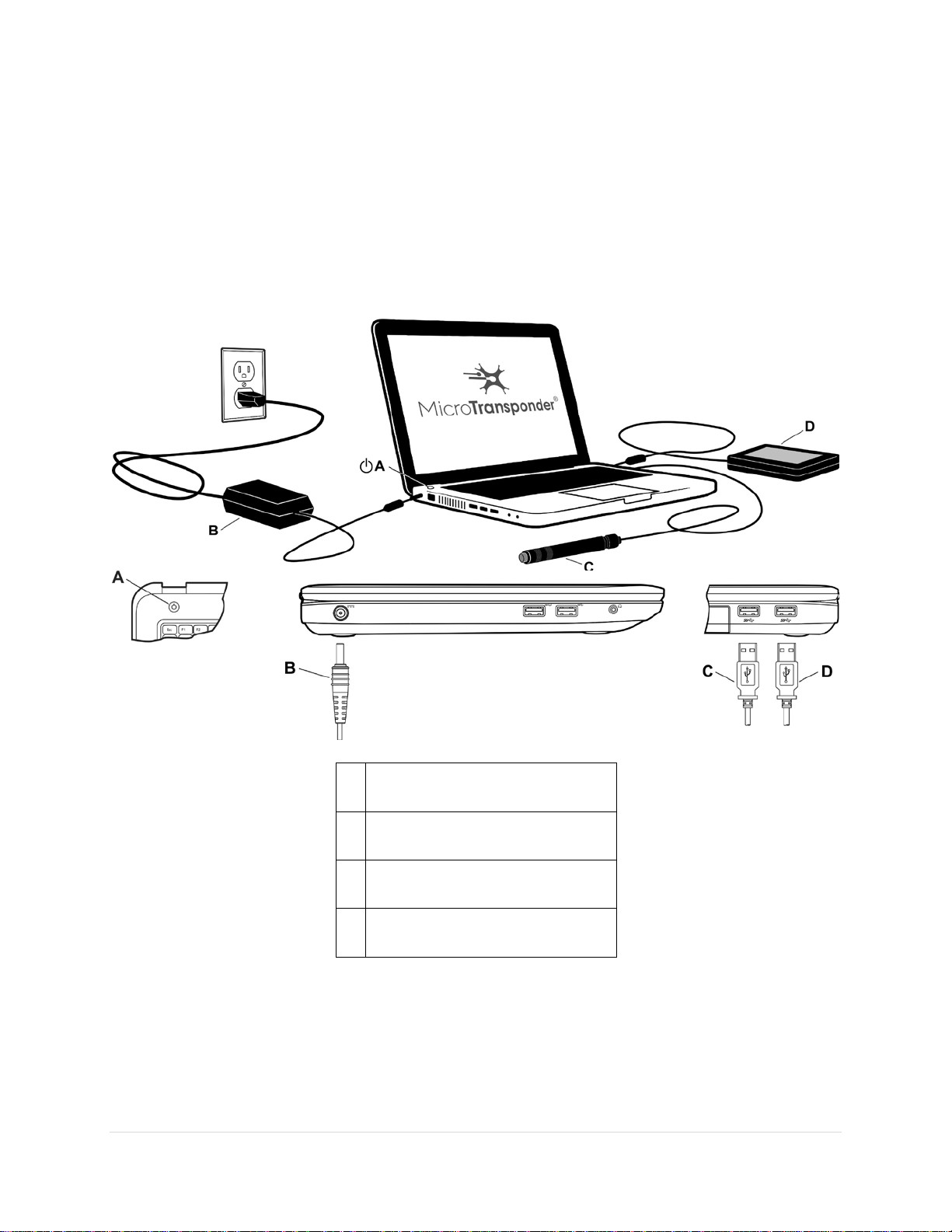
Figure 2.1: SAPS Hardware Set-up Overview..................................................................................10
Figure 2.22: Startup Menu Screen—Welcome Menu .......................................................................11
Figure 3.1: Log In.............................................................................................................................13
Figure 3.2: Startup Menu Screen—Physician Mode.........................................................................14
Figure 3.3: Buttons Versus Tabs......................................................................................................14
Figure 3.4: Blue Text Indicates Settings Have Not Been Saved.......................................................15
Figure 4.1: Program Implant.............................................................................................................17
Figure 4.2: Disconnect .....................................................................................................................17
Figure 4.3: Blank Serial #.................................................................................................................17
Figure 4.4: Interrogate Button on Screen .........................................................................................18
Figure 4.5: Contact Implant..............................................................................................................18
Figure 4.6: Select Button..................................................................................................................18
Figure 4.7: Serial # and Battery Status.............................................................................................19
Figure 4.8: Time Button....................................................................................................................19
Figure 4.9: Time19
Figure 4.10: Patient ID .....................................................................................................................20
Figure 4.11: Implant Setting Parameters..........................................................................................21
Figure 4.12: Amplitude.....................................................................................................................21
Figure 4.13: Frequency....................................................................................................................22
Figure 4.14: Train Duration ..............................................................................................................22
Figure 4.15: Pulse Width..................................................................................................................23
Figure 4.16: Stim Test Mode............................................................................................................24
Figure 4.17: Implant Settings............................................................................................................24
Figure 4.18: Therapist Trigger Mode................................................................................................25
Figure 4.19: Implant Settings............................................................................................................26
Figure 4.20: Lead Impedance Check................................................................................................27
Figure 4.21: High Lead Impedance Notification................................................................................27
Figure 4.22: Low Lead Impedance Notification.................................................................................28
Figure 4.23: Lead Impedance Displayed..........................................................................................28
Figure 6.1: Reset Button ..................................................................................................................37
Figure 6.2: Password Prompt...........................................................................................................37
Figure 6.3: Accept Reset..................................................................................................................38
Figure 7.1: Magnet Mode.................................................................................................................40
Figure 7.2: Magnet Mode Session History........................................................................................41
Figure 7.3: Magnet Mode Prompt.....................................................................................................41
Figure 8.1: Patient Log File—Read Statistics...................................................................................43
Figure 8.2: Patient Log File—Export Log..........................................................................................44
Figure 10.1: IPG Settings for MRI Procedures .................................................................................46
Figure 13.1: Telemetry Lost .............................................................................................................50
Figure 16.1: Wireless Transmitter ....................................................................................................53

26-0002-0005/0 (en) (2022) 6
LIST OF TABLES
Table 16.1: Characteristics of the Wireless Transmitter....................................................................54
Table 17.1: Guidance and Manufacturer’s Declaration—Electromagnetic Emissions.......................55
Table 17.2: Guidance and Manufacturer’s Declaration—ESD and Power Fluctuations ....................56
Table 17.3: Guidance and Manufacturer’s Declaration—Radiated Electromagnetic Fields...............57
Table 17.4: Recommended Separation Distance Between Portable and Mobile RF Communication
Equipment and the Wireless Transmitter.......................................................................58

26-0002-0005/0 (en) (2022) 7
1 DEVICE DESCRIPTION
The non-implantable components of the MicroTransponder®Vivistim®Paired VNS™System
(Vivistim®System) include the Stroke Application & Programming Software (SAPS) and
Wireless Transmitter (WT). The SAPS and the WT enable the clinician to set Paired VNS™
parameters, initiate a therapy session, and test and modify the implanted device and its
settings. The complete device system (the Vivistim®System) is shown in Figure 1.1.
A
B
Figure 1.1: (A) Device Placement, (B) In-office Set-up
The Vivistim®System, when used as intended, provides a drug-free way to treat upper extremity
motor deficits associated with a stroke by pairing rehabilitation movements with Vagus Nerve
Stimulation. The Lead electrodes are attached to the left vagus nerve in the neck. The Lead is
tunneled from the neck to the chest, where it is connected to the Implantable Pulse Generator
(IPG), and the IPG is placed subcutaneously (or sub-muscularly) in the pectoral region. The
SAPS is delivered to the clinician preloaded onto a commercially available laptop. The SAPS,
via the WT, allows the clinician to program the output settings of the IPG (e.g., amplitude,
frequency, pulse width) and read the status and history of the IPG. The SAPS also stores the
number of stimulations, task performed, and IPG status that occur for each rehabilitation activity
for future review by the clinician.

26-0002-0005/0 (en) (2022) 8
The SAPS and WT allow the implanted components (the IPG and Lead) to stimulate the vagus
nerve while a rehabilitation movement occurs. The therapist initiates the stimulation using a
USB push button or mouse click, so as to synchronize the stimulation with an appropriate
timepoint during rehabilitation movements. When directed by a physician and with appropriate
programming to the IPG, the patient can initiate at-home use by swiping a magnet over the IPG
implant site. Swiping activates the IPG to deliver stimulation for ~ 30 minutes1while
rehabilitation movements are performed at home. At-home use does not require the use of
SAPS or the WT. In addition, the magnet provided to the patient to initiate home therapy also
has a safety feature; if the patient desires to stop stimulation, holding the magnet over the
device stops stimulation for as long as it is held over the device.
The physician or therapist is responsible for training the patient on use of the magnet and
providing the Microtransponder®Vivistim®Paired VNS™System Manual for Patients. The
Microtransponder®Vivistim® Paired VNS™System Quick Start Guide for Patients is
located in the Microtransponder®Vivistim®Paired VNS™System Manual for Patients, and an
additional copy is on the last page of this manual.
Software capabilities include:
• Use of SAPS with the WT by a rehabilitation therapist or neurologist or other physician to
interrogate and program an IPG’s parameters and assess IPG function
• Use of SAPS with the WT by a rehabilitation therapist or neurologist or other physician to
initiate a therapy session during rehabilitation at the clinic
• Use of SAPS without the WT to display the operating histories of all the IPGs interrogated
with the laptop
• Use of screen displays that provide prompts and messages to aid in interrogating and
programming
Other User Manuals:
• Microtransponder®Vivistim®Paired VNS™System Manual for Patients
• Microtransponder®Vivistim®Paired VNS™System Implantable Device Manual for
Healthcare Professionals
1.1 Intended Use / Indication
The MicroTransponder®Vivistim®Paired VNS™System is intended to be used to stimulate the
vagus nerve during rehabilitation therapy to reduce upper extremity motor deficits and improve
motor function in chronic ischemic stroke patients with moderate to severe arm impairment.
SAPS is intended for use only with the MicroTransponder Implantable Pulse Generator (IPG)
and MicroTransponder Wireless Transmitter.
1The clinician is responsible for establishing the duration of stimulation according to clinical best practices.

26-0002-0005/0 (en) (2022) 9
1.2 SAPS Warnings
NOTE: The SAPS system, as described herein, should only be used with equipment described
in this manual. SAPS should not be used with medical device equipment other than the
Vivistim®System.
WARNING: Do not modify this equipment without authorization of MicroTransponder.
WARNING: The use of any software other than that specified herein will violate safety,
effectiveness, and design controls of the programmable devices, and such use may result
in an increased risk to users and patients.
1.3 SAPS Package Contents
The SAPS package contains the following:
• Software (installed on commercially available laptop)
• Documentation
1.4 WT Package Contents
The WT package contains the following:
• 1 Wireless Transmitter
• Documentation

26-0002-0005/0 (en) (2022) 10
2 GETTING STARTED
2.1 Stroke Application & Programming Software (SAPS) Hardware Setup
Figure 2.1: indicates the proper setup:
1. Connect the power cord to the power port on the laptop and connect the other end to the
wall outlet.
2. Connect the WT to a USB port on the laptop.
3. (Optional) Connect the push button to a USB port on the laptop.
A Power Button
B Power Cord
C Push Button
D Wireless Transmitter
Figure 2.1: SAPS Hardware Set-up Overview

26-0002-0005/0 (en) (2022) 11
2.2 How to Use the Stroke Application & Programming Software (SAPS)
The SAPS has been pre-installed on the commercially available laptop provided.
1. Position the laptop within 1 m of the IPG implanted in the patient’s left chest.
2. Turn the laptop on (Typically the ON button is directly below the laptop screen on the front
left, as shown above in Figure 2.1:, although it may also be on the front right or side of the
computer; press down).
3. The laptop will power up in the “microtransponder” login state. Log into the computer
using the password provided.
CAUTION: If the laptop does not automatically launch the SAPS, then please reboot your
computer and re-launch SAPS (see Section 13 Troubleshooting ). If this does not
correct the issue or you have additional problems, please contact MicroTransponder per
Section 18: Information and Support.
.
4. The SAPS loaded onto the laptop will then launch to the Startup Menu Screen (Welcome
menu) (see Figure 2.22). Before proceeding to the next section, ensure that you have
arrived at this Startup Menu Screen.
Figure 2.22: Startup Menu Screen—Welcome Menu
CAUTION: If the computer does not display the Startup Menu Screen, see Section 12:
Precautions, Warnings, Contraindications, and Hazards and Section 13:
Troubleshooting before proceeding.
For proper operation and communication, the USB plug of the WT must be plugged into a USB
port of the laptop. The WT should be positioned within 1 m of the implanted IPG for proper
communication. The Interface indicator on the SAPS user interface screen will be green in color

26-0002-0005/0 (en) (2022) 13
3 USING THE SOFTWARE (SAPS)
Unless a Log In has been performed by entering the appropriate password, the only buttons
enabled in the Welcome menu are the Patient Log File and VNS Pairing Therapy buttons
(see Figure 2.22). These buttons allow the physician or therapist to assign a task and perform a
therapy session. To access the rest of the program features, the Log In button must be selected
(see Figure 3.1).
Figure 3.1: Log In
To log in and access all other SAPS screens, select the Log In button (upper right menu bar,
4th button from the right) and type the password provided into the pop-up shown in Figure 3.1.
At this point the program is “unlocked,” and all menus in the program are available (see Figure
3.2).

26-0002-0005/0 (en) (2022) 14
Figure 3.2: Startup Menu Screen—Physician Mode
Notice that the orange Log In button has toggled to Log Out (circled in Figure 3.2) so that, if
desired, the user may select the Log Out button and once again remove access to the
additional SAPS screens.
After a period of 15 minutes, the Log In will time out, and you will need to log back in to
continue the session.
3.1 Buttons Versus Tabs
Within the SAPS, there are two types of clickable elements: buttons and tabs (see Figure 3.3).
Figure 3.3: Buttons Versus Tabs

26-0002-0005/0 (en) (2022) 15
The buttons on the Welcome screen initiate functions such as programming the implant,
accessing VNS Pairing Therapy, or accessing the Patient Log File. For example, the Program
Implant button sends a signal from the WT to the IPG to update the IPG settings with those
currently saved in the SAPS.
The tabs at the top of any screen allow the physician to manage the settings of each function.
For example, the Program Implant tab allows the physician to review and edit the IPG settings.
3.2 Parameter Text Color
When changing parameters for therapy, blue text indicates settings that have not been saved to
the IPG (i.e., the Download to IPG button has not been pressed), and black text indicates
settings that have been saved to the IPG. In Figure 3.4 below, Frequency, Train Duration,
Pulse Width, Train Period, and Magnet Mode have been saved to the IPG, while Amplitude
has not.
Figure 3.4: Blue Text Indicates Settings Have Not Been Saved
3.3 Overview of SAPS Menus (Tabs) Used for Therapy
Each tab at the top of the SAPS screen corresponds to a particular capability of the system,
denoted by the tab’s name.
NOTE: See Figure 3.3 for the location of the menus and the corresponding buttons used to
access the menus described in this section.
CAUTION: New parameters and therapy modes are not input into the IPG and remain
blue in color until the Test function or the Download Settings to IPG function is used.
Always verify that the intended parameters and therapy modes are programmed into the
IPG. The suggested method of doing so is by interrogating the IPG and comparing the
displayed values to those intended to be programmed. Properly programmed parameters
and therapy modes display black in color.
3.3.1 Program Implant Overview
The first tab, Program Implant, is used by the physician or therapist to set the patient
information, stimulation settings, and therapy mode(s) and allows for impedance checks during
implant and follow-up visits. See Section 4: Programming the Implant for more detail.
3.3.2 VNS Pairing Therapy Overview
The second tab, VNS Pairing Therapy, is used to actually deliver therapy and assign the
correlating rehabilitation task. It allows the therapist to either:

26-0002-0005/0 (en) (2022) 16
• trigger the delivery of stimulation so that stimulation can be synchronized with a specific
rehabilitation movement using the On-Demand Mode (see Section 5.1: Therapist
triggered therapy for more detail), or
3.3.3 Patient Log File Overview
The third tab, Patient Log File, allows the physician or therapist to review on the computer
screen or print out specific saved settings that were utilized during the rehabilitation session. For
example, the therapist can review each stimulation usage for a given task. See Section 8
Patient Log File for more detail.

26-0002-0005/0 (en) (2022) 17
4 PROGRAMMING THE IMPLANT
The Program Implant menu (see Figure 4.1) allows the user to set the patient information, test
and set stimulation parameters, set therapy mode(s), and check impedance during implant and
follow-up visits.
Figure 4.1: Program Implant
4.1 Connecting to a Specific IPG
Perform these six steps before therapy for each patient to connect to their specific IPG.
1. Select the Disconnect button to disconnect any IPG that is connected to SAPS that is
different from your patient’s IPG Serial # (see Figure 4.2). Select “Continue” when
prompted to confirm.
Figure 4.2: Disconnect
2. Verify there is no Serial # displayed in SAPS; you will see 3 dashes next to “Serial” if this
is the case (see Figure 4.3).
Figure 4.3: Blank Serial #

26-0002-0005/0 (en) (2022) 18
3. Select Contact Implant to allow the SAPS to find the patient’s IPG (see Figure 4.4 and
Figure 4.5).
Figure 4.4: Interrogate Button on Screen
Figure 4.5: Contact Implant
4. A pop-up menu will appear. Select the IPG whose Serial # matches the one on the
patient’s Patient Identification Card by clicking on their specific IPG and then pressing the
Select button (circled in Figure 4.6).
Figure 4.6: Select Button

26-0002-0005/0 (en) (2022) 19
5. Verify that the selected IPG’s Serial # is displayed to the right of “Serial”, and check the
IPG battery’s status, as indicated by the symbol to the right of “Implant Battery” (see
Figure 4.7). A green circle indicates an adequately full battery. “ERI” or “EOL” displayed in
place of the green circle indicates that the IPG’s battery is close to its end of life. You may
want to verify the Lead impedance. See Section 4.5: Impedance.
Figure 4.7: Serial # and Battery Status
6. You may also want to verify that the IPG date and time are synched with the computer.
See the steps below.
a. Press the Time button (circled in Figure 4.8:).
Figure 4.8: Time Button
b. A window appears showing the Current Device Time and Current PC Time (see Figure
4.9). Generally, the Set with PC Time button on the right-hand side is used to
synchronize time. Each button can be used as described here:
oThe Get Time button to view the current IPG time
oThe Set Time button to manually set the IPG time
oThe Set with PC Time button to set the IPG time to the current PC time
Figure 4.9: Time

26-0002-0005/0 (en) (2022) 20
4.2 Patient Information (Optional)
The user may enter a patient identification, such as the patient’s initials or medical record
number, into the SAPS if the user chooses. If the user does not provide a patient identification,
the IPG’s unique serial number can be used.
1. Enter the patient identification into the Patient ID field, as shown in Figure 4.10.
2. Program this Patient ID to the IPG by selecting the Download Settings to IPG button,
located in the center of the screen (see Figure 4.1).
This is only required to be performed once. SAPS will recognize the programmed Patient ID
each time the IPG is interrogated. The IPG retains this information indefinitely.
Figure 4.10: Patient ID
4.3 Implant Settings
To enable each of the therapy modes, the button next to the desired Therapy Mode is selected
and turned on.
1. Turn on your desired Therapy Mode to adjust the Implant Settings.
2. Each of the implant setting parameters available in the Implant Settings menu has a box
next to the setting (see Figure 4.11). Select the box to display all available parameters in a
drop-down box.
3. Select the appropriate value for each parameter, and program the parameters into the IPG
using the Download Settings to IPG function. Examples of parameters are shown in
Figure 4.12 through Figure 4.15.
4. Once you choose new implant settings, always verify that the implant setting parameters
chosen are tolerable for the patient using the Stim Test Mode function. See Section
4.4.1:Stim Test Mode.
Once the values programmed via the Test function or the Download Settings to IPG function
are input into the IPG, all subsequent therapy sessions will be performed at these parameters.
The user can modify the parameters at any time by selecting new parameters and programming
them into the IPG.
This manual suits for next models
1
Table of contents
Popular Medical Equipment manuals by other brands

Chattanooga
Chattanooga VitalStim Plus quick start guide

Leisegang
Leisegang 1E light Installation and operating instructions

Future Mobility Healthcare
Future Mobility Healthcare PRISM Supreme Installation and operating instructions

Siemens
Siemens Sonoline G20 Maintenance Instruction

LUMENIS
LUMENIS Array LaserLink Operator's manual

Welch Allyn
Welch Allyn 49500 Service manual