BIO UV UV3205HO Manual

UV_SN-GB.doc Copyright BIO-UV - 29/09/2008
Marque, Modèles et Brevets déposés - Produits exclusifs Page 1
REACTORS IN THE UV MULTILAMP RANGE
WITHOUT CLEANING
(Picture UV 4205 HO)
INSTALLATION AND MAINTENANCE
MANUAL

UV_SN-GB.doc Copyright BIO-UV - 29/09/2008
Marque, Modèles et Brevets déposés - Produits exclusifs Page 2
UVPS subsidiary of the BIO-UV
COMPLIANCE CERTIFICATE
CERTIFICATE OF CONFORMITY
BIO-UV and this subsidiary, hereby declares that the following products
UV multilamp range
comply to the following standards:
NF EN 60598-1 + A11 (2001)
CEM : EN55015 (Ed.00) + A1 (Ed.01)
Number and year of EC stamp:
CG-03-006 dated 29/01/2003
LS-03-51003/NL dated 20/02/03
Benoît GILLMANN
Chairman and Managing Director of BIO-UV
Société BIO-UV SA
ZAC La Petite Camargue
34400 LUNEL France
Hotline: + 33 (0)890 71 03 70 (0,15€/min)

UV_SN-GB.doc Copyright BIO-UV - 29/09/2008
Marque, Modèles et Brevets déposés - Produits exclusifs Page 3
We thank you for choosing a BIO-UV reactor.
Our equipment has been designed to give you reliable and safe operation for many years to come.
The BIO-UV reactors have been designed for speed and ease of installation.
Their design also makes them easy to maintain..
Read these instructions carefully in order to optimise the operation of your reactor.
CONTENTS : pages
A. TECHNICAL CHARACTERISTICS ...............................................................................................4
B. MAINTENANCE FILE ......................................................................................................................5
C. WARNINGS AND SAFETY ..............................................................................................................6
D. STARTING UP ....................................................................................................................................8
E. MANUAL OF THE MONITEUR (Option) ......................................................................................9
F. CHANGING UV LAMP AND QUARTZ SLEEVE.......................................................................10
G. ELECTRICAL UNIT........................................................................................................................12
H. BLOWN UP VIEW............................................................................................................................13
ANNEX 1: Clearance dimensions – Blown up view – Designation
ANNEX 2: Electrical diagrams

UV_SN-GB.doc Copyright BIO-UV - 29/09/2008
Marque, Modèles et Brevets déposés - Produits exclusifs Page 4
A. TECHNICAL CHARACTERISTICS
UV HO RANGE 3205 HO 4205 HO 5205 HO 6205 HO 6273 HO
REACTOR
Material Stainless steel 316L
Finish Mirror polish
Maximum service pressure 3Bars
Weight (kg) (1) 25 37
Øand body length (mm) 204 x 830 273 x 830
Overall length (mm) (1) 980 1010
Volume (litres) 26 49
Connection type Stainless steel 316 L male collar
Standard Connection 2 ½ inches
ELECTRICAL UNIT
Type ABS
Dimensions (mm) 400 x 300 x 180 500 x 400 x 200
Weight (kg) 6 8 9
Power supply Single-phase 240V
Power supply wiring 3G1,5mm²
Differential protection 30 mA
Thermo magnetic protection 6 A
Circuit breaker tripping curve Curve C
Fuse -
On / Off switch Yes
Power on indicator light -
UV lamp indicator light Yes
Display (1) Electro-mechanic hour counter
Protection index IP 54
UV-C LAMP
Number of lamps 34566
Electrical power 261 W 348 W 435 W 522 W 522 W
Unit UV-C power 28 W 28 W 28 W 28 W 28 W
Total UV-C power 84 W 112 W 140 W 168 W 168 W
Average lifetime 13 000 h 13 000 h 13 000 h 13 000 h 13 000 h
(1) Caution, with a cleaning system these values change.
UV_SN-GB.doc Copyright BIO-UV - 29/09/2008
Marque, Modèles et Brevets déposés - Produits exclusifs Page 5
B. MAINTENANCE FILE
CAUTION:
This sheet must be kept up to date.
It provides a record of the reactor’s operating cycle.
Date Action By
UV_SN-GB.doc Copyright BIO-UV - 29/09/2008
Marque, Modèles et Brevets déposés - Produits exclusifs Page 6
C. WARNINGS AND SAFETY
BIO-UV reactors are ready to install, no works is required inside the reactor.
Read all the instructions in this manual before switching on the BIO-UV appliance.
INSTALLATION
RECOMMANDATIONS
The reactor must be installed:
-in a technical room, protected from light and rain,
-after the filter(s),
-in a dry zone, ambient humidity must be < 80%.
The installation zone temperature must be within 0°C and 40°C.
Keep any sources of hydrochloric acid vapours away from the installation.
The electrical unit should be positioned:
-so that it is protected from water,
-at eye level.
The air vent of fan must not be obstructed.
The cable length between the UV reactor and its electrical unit must not be modified.
Make sure you choose a position where the lamp can be taken out:the AVAILABLE HEIGHT
should be double the total height of the appliance.
MThe equipment must always be filled with water when operating and the
air must be bled out of it.
We recommend the presence of a by-pass.
MBefore accessing the connection terminals, ensure that all supply circuits
are disconnected.
MThe reactor installation as a whole must be protected with a suitably adapted
circuit breaker.
(See A. Technical characteristics)
MCheck that cable complies with legislation and the required power level.
(See A. Technical characteristics)
MIf, for installation reasons, the power supply cables connecting the cabinet to
the reactor have to be shortened, take care to fully crimp the new end fittings
at each end of the cables.

UV_SN-GB.doc Copyright BIO-UV - 29/09/2008
Marque, Modèles et Brevets déposés - Produits exclusifs Page 7
USE AND MAINTENANCE
MAllow the ultraviolet lamp to cool for at least 30 minutes before handling.
MNever look at the ultraviolet lamps when lit. This may cause severe injuries
or burns and may even lead to loss of eyesight.
MDo not touch the ultraviolet lamp with bare hands, as these would leave
impurities that shorten the life of the lamp. If you do touch it: clean with alcohol
or white vinegar.
MNever unscrew the quartz tube sealing nut when the reactor is on load as the
quartz tube could be blown out of the reactor with force and injure you.
MDo not use the reactor if the power supply wire is worn or damaged.In this
case it should be replaced.
MIf the connecting cable between the reactor and the electrical cabinet is
damaged, it must be replaced by a special cable available as a spare part.
MEven when stopped, power is present in the electrical unit so make sure
that the main power supply upstream of the electrical cabinet is switched off
before carrying out any work on the equipment.
MTo avoid electric short-circuits, do not place the electric wires or the reactor in
the pool water or in any other maintenance or cleaning fluid.
MDo not restart the system until the electric unit, the covers exterior elements of
the reactor are correctly back in place.
MDo not use the BIO-UV reactor for any other use than that for which it was
designed.

UV_SN-GB.doc Copyright BIO-UV - 29/09/2008
Marque, Modèles et Brevets déposés - Produits exclusifs Page 8
D. STARTING UP
1 Check that the reactor BIO-UV is properly mounted on your installation.
2Start your installation to fill the pipes with water.
3
Purge the air of the reactor:
-close the valve upstream of the reactor,
-unscrew the drain plug on the top of the body reactor,
- open the valve upstream of the reactor slowly and close it when the water is
forced out through the drain plug,
- re-tighten the drain plug and open the valve upstream of the reactor.
4Check the water tightness of the unit.
5Check that the electrical connection of the UV unit is compliant.
Check that the top of the reactor is correctly positioned.
6Set the ON/OFF UV unit switch to the ON position and check that the lamps
are working properly: the indicator light for each lamp should be lit.
7 Check that the hour counter is running.

UV_SN-GB.doc Copyright BIO-UV - 29/09/2008
Marque, Modèles et Brevets déposés - Produits exclusifs Page 9
E. MANUAL OF THE MONITEUR (Option)
Your UV equipment is fitted with a UV monitor and a UV-C radiation measurement cell.
This monitor will indicate the gradual reduction in the intensity of the lamps throughout their lifetime but
may also provide a warning of dirt being deposited in the quartz sleeve or on the UV-C radiation
measurement cell.
OPERATION
1. Switch on the lighted switch on the front of the electrical unit..
2. The UV C lamps will heat up to their maximum output level in 2 to 5 minutes (depending on the
temperature of the liquid being treated).
3. You now need to calibrate the cell in its liquid environment:
CALIBRATION of the UV-C ray measurement cell
(Do it at each change of lamp and cleaning of sensor)
1. Open the front of the electrical unit.
2. Take a small screwdriver.
3. Turn gently the small screw at the back of the monitor (next to a green LED) clockwise
until the LED light green.
Calibration should result in a green fixed LED on the front and back face
of the UV Monitor.
UV MONITOR
UV INTENSITY
< 50 % 50…70 % > 70 %
Main Pre OK
Alarm alarm

UV_SN-GB.doc Copyright BIO-UV - 29/09/2008
Marque, Modèles et Brevets déposés - Produits exclusifs Page 10
F. CHANGING UV LAMP AND QUARTZ SLEEVE
When a lamp is defective, we recommend to change all lamps and to keep those still valid for the next
repairs.
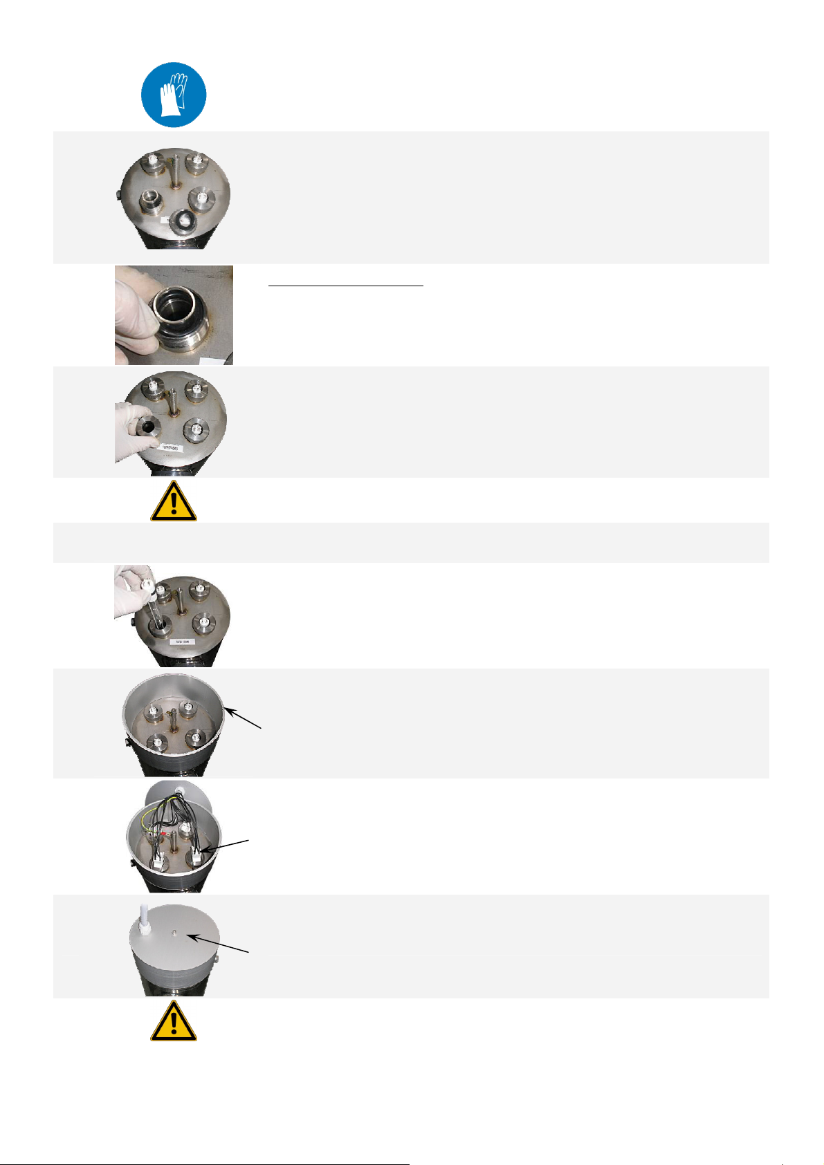
1SWITCH OFF the reactor CUT the POWER source and EMPTY IT.
2 Unscrew and remove the cover.
3 Unplug each connector of lamp and the ground plug if necessary.
4 Remove the support from the cover.
5 Make sure that the UV lamp is cooled before handle it.
6
Take out the UV lamp (if necessary use the connector) and place it on a clean
and soft surface.
Carry out this operation CAREFULLY taking care not to place your
fingers outside the cap.
7
Undo the stainless steel nut
Remove the flat washer.
8
Gently remove the quartz sleeve:
Insert a thumb or finger in the sleeve and withdraw it until the seal comes
free from its housing.
9Take hold of the quartz sleeve and extract it fully making sure that you keep
it correctly aligned with the axis.
UV_SN-GB.doc Copyright BIO-UV - 29/09/2008
Marque, Modèles et Brevets déposés - Produits exclusifs Page 11
10 Clean the quartz sleeve with acid or white vinegar or replace it if necessary.
11
With a finger inside the sleeve, insert the quartz sleeve into the equipment up
to its housing at the bottom of the reactor.
The quartz should protrude slightly, itshould not be dropped right to the
bottom.
If the quartz is correctly positioned in the base, when you press it, it feels
flexible (pneumatic effect).
12
Change the quartz seals:
(Put a new seal at each change of lamp)
Mlubricate the seal using food grade grease,
Mposition it around the sleeve,
Mpush it fully home in its housing using your nail (do not use tools).
13
Replace the flat washer.
Re-tighten the nut by hand, tightening it normally.
14 Put the installation back in pressure before the reassembly of lamps and
check that there is no leakage in the quartz sleeve.
15 Take hold of the new lamp taking care not to place your fingers outside the cap.
(if you do, clean the lamp with a soft cloth and some methylated spirits).
16 Fully engage the lamp in the quartz sleeve.
17 Refit the support from the cover.
18
Reconnect each lamp connector. (Do not force the connector into place:
There is a specific connection direction) and clip the connector onto the
stainless steel nuts.
Reconnect the grounding terminal lug.
19 Refit the cover.
20 Check the calibration of the UV-C ray measurement cell.
(See chapter MANUAL OF THE MONITOR).

UV_SN-GB.doc Copyright BIO-UV - 29/09/2008
Marque, Modèles et Brevets déposés - Produits exclusifs Page 12
G.ELECTRICAL UNIT
Electrical unit without monitor:
References and quantities by reactor
n° Designation Tag 3205 HO Qty 4205 HO Qty 5205 HO Qty 6205 HO Qty 6273 HO Qty
1Differential circuit breaker DELE003555 1 ELE003555 1 ELE003555 1 ELE003555 1 ELE003555 1
2On / Off switch CELE000271 1 ELE000271 1 ELE000271 1 ELE000271 1 ELE000271 1
3Orange light HELE002652 3 ELE002652 4 ELE002652 5 ELE002652 6 ELE002652 6
4Hour counter CELE000026 1 ELE000026 1 ELE000026 1 ELE000026 1 ELE000026 1
5Ballast BBAL000026 3BAL000026 4BAL000026 5BAL000026 6BAL000026 6
6Fan M- - - - ELE001087 1 ELE001087 1 ELE001087 1
Electrical unit with monitor Pro8:
References and quantities by reactor
n° Designation Tag 3205 HO Qty 4205 HO Qty 5205 HO Qty 6205 HO Qty 6273 HO Qty
1Differential circuit breaker DELE003555 1ELE003555 1ELE003555 1ELE003555 1ELE003555 1
2On / Off switch CELE000271 1ELE000271 1ELE000271 1ELE000271 1ELE000271 1
3Orange light HELE002652 3ELE002652 4ELE002652 5ELE002652 6ELE002652 6
4Hour counter CELE000026 1ELE000026 1ELE000026 1ELE000026 1ELE000026 1
5Monitor Pro8 ELE000619 1ELE000619 1ELE000619 1ELE000619 1ELE000619 1
6Ballast BBAL000026 3BAL000026 4BAL000026 5BAL000026 6BAL000026 6
7Fan M- - - - ELE001087 1ELE001087 1ELE001087 1
1
2
4
3
5
1
2
4
3
5
6
UV_SN-GB.doc Copyright BIO-UV - 29/09/2008
Marque, Modèles et Brevets déposés - Produits exclusifs Page 13
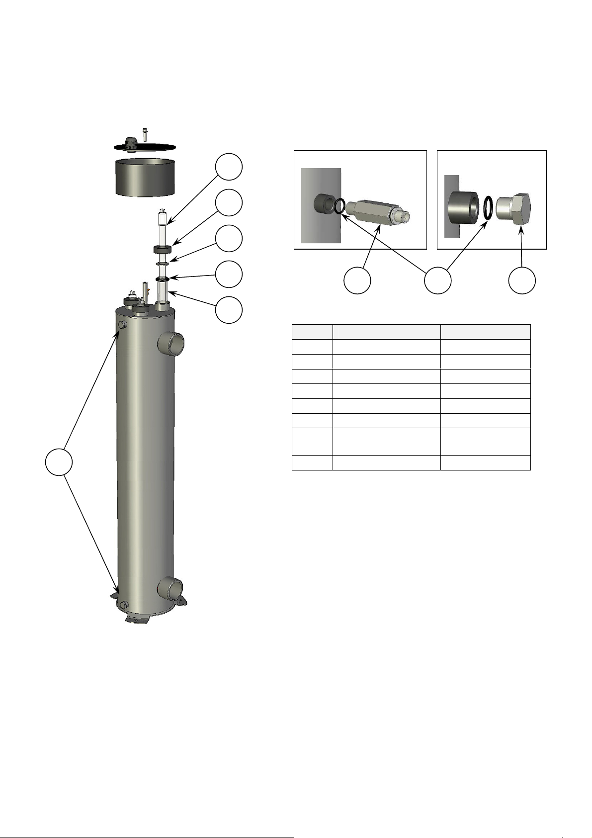
H.BLOWN UP VIEW
N° Designation Reference
1Lamp LPE000005
2Nut USI000018
3Flat washer PIE000659
4Seal JTS000100
5Quartz sleeve QUA000018
6Drain plug ACC000410
7UV Sensor ELE000489
or ELE002114*
8Seal JTS000230
*Only for UV units with a monitor MIII
UV Sensor: Drain plug
7
6
8
4
3
2
1
6
5
UV_SN-GB.doc Copyright BIO-UV - 29/09/2008
Marque, Modèles et Brevets déposés - Produits exclusifs Page 14
WARRANTIES
Units in the BIO-UV range are guaranteed subject to the following conditions:
-5years for the stainless steel reactor (materials and welding) except in the event of use in a highly
corrosive environment (brackish or very salty, e.g.: seawater).
-2 years for all other components excepting the UV lamp (consumable).
Electrical components are not guaranteed against overvoltage and lightening damage.
Caution: the quartz tube and the lamp are not guaranteed against breakage.
-Faulty parts must be returned to BIO-UV, with details of the unit type and serial number, for
exchange after technical evaluation.
-Shipping costs will be shared between the retailer and BIO-UV.
-The guarantee runs from the day of installation: this date must be notified to BIO-UV by
returning the guarantee validation form by post or fax.
Caution: If the guarantee validation form is not returned within one month
following purchase of the unit, BIO-UV will use the month and year of manufacture
of the unit as the guarantee start date.
-If the instructions for installation and use are not followed, BIO-UV cannot accept
responsibility and the guarantees will be considered null and void.
How to contact the BIO-UV Team.
Société BIO-UV SA
ZAC La Petite Camargue
34400 LUNEL France
Hotline: + 33 (0)890 71 03 70 (0,15€/min)

UV_SN-GB.doc Copyright BIO-UV - 29/09/2008
Marque, Modèles et Brevets déposés - Produits exclusifs Page 15
ANNEX 1
Clearance dimensions
Blown up view
Designation
UV_SN-GB.doc Copyright BIO-UV - 29/09/2008
Marque, Modèles et Brevets déposés - Produits exclusifs Page 16
ANNEX 2
Electrical diagrams
Table of contents


