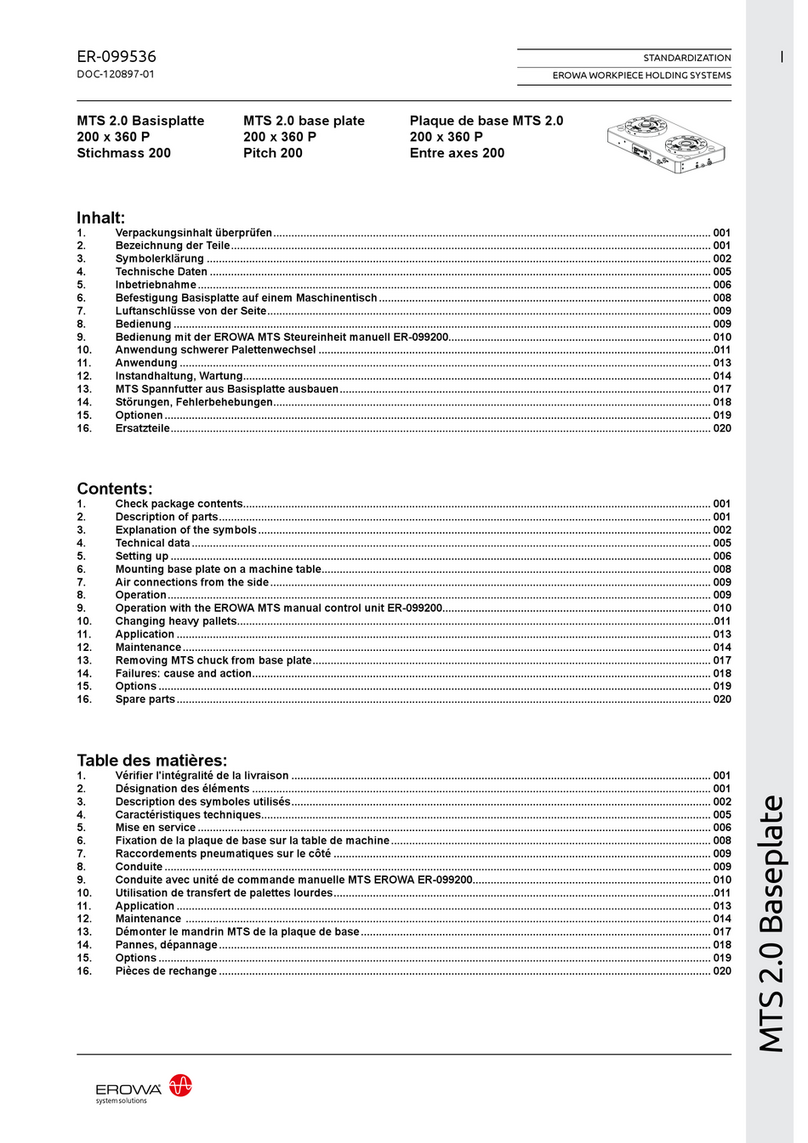
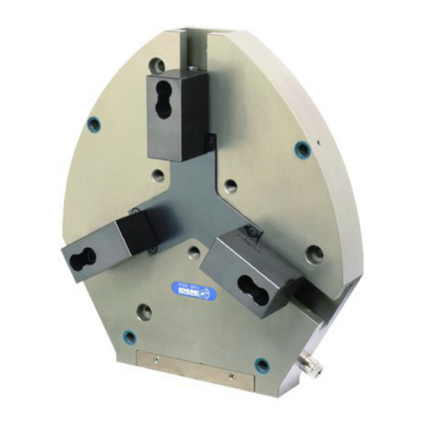
erowa ER-103311 User manual

MTS 2.0 Baseplate
ER-103311 I
STANDARDIZATION
EROWA WORKPIECE HOLDING SYSTEMS
DOC-109457-01
MTS 2.0 Basisplatte
360x560 P
Stichmass 200
Inhalt:
1. Verpackungsinhalt überprüfen ................................................................................................................................................. 001
2. Bezeichnung der Teile ............................................................................................................................................................... 001
3. Symbolerklärung ....................................................................................................................................................................... 002
4. Technische Daten ...................................................................................................................................................................... 005
5. Inbetriebnahme .......................................................................................................................................................................... 006
6. Befestigung Basisplatte auf einem Maschinentisch .............................................................................................................. 008
7. Luftanschlüsse von der Seite ................................................................................................................................................... 009
8. Bedienung .................................................................................................................................................................................. 009
9. Bedienung mit der EROWA MTS Steureinheit manuell ER-099200........................................................................................011
10. Anwendung schwerer Palettenwechsel .................................................................................................................................. 012
11. Anwendung ................................................................................................................................................................................014
12. Instandhaltung, Wartung........................................................................................................................................................... 015
13. MTS Spannfutter aus Basisplatte ausbauen ........................................................................................................................... 018
14. Störungen, Fehlerbehebungen ................................................................................................................................................. 019
15. Optionen ..................................................................................................................................................................................... 020
16. Ersatzteile ................................................................................................................................................................................... 021
MTS 2.0 Baseplate
360x560 P
Pitch 200
Contents:
1. Check package contents ........................................................................................................................................................... 001
2. Description of parts ................................................................................................................................................................... 001
3. Explanation of the symbols ...................................................................................................................................................... 002
4. Technical data ............................................................................................................................................................................ 005
5. Setting up ................................................................................................................................................................................... 006
6. Mounting base plate on a machine table ................................................................................................................................. 008
7. Air connections from the side .................................................................................................................................................. 009
8. Operation .................................................................................................................................................................................... 009
9. Operation with the EROWA MTS manual control unit ER-099200..........................................................................................011
10. Changing heavy pallets ............................................................................................................................................................. 012
11. Application ................................................................................................................................................................................. 014
12. Maintenance ............................................................................................................................................................................... 015
13. Removing MTS chuck from base plate .................................................................................................................................... 018
14. Failures: cause and action ........................................................................................................................................................ 019
15. Options ....................................................................................................................................................................................... 020
16. Spare parts ................................................................................................................................................................................. 021
MTS 2.0 Plaque de base
360x560 P
Entre axes 200
Table des matières:
1. Vérifier l'intégralité de la livraison ........................................................................................................................................... 001
2. Désignation des éléments ........................................................................................................................................................ 001
3. Description des symboles utilisés ........................................................................................................................................... 002
4. Caractéristiques techniques ..................................................................................................................................................... 005
5. Mise en service .......................................................................................................................................................................... 006
6. Fixation de la plaque de base sur la table de machine .......................................................................................................... 008
7. Raccordements pneumatiques sur le côté ............................................................................................................................. 009
8. Conduite ..................................................................................................................................................................................... 009
9. Conduite avec unité de commande manuelle MTS EROWA ER-099200................................................................................011
10. Utilisation de transfert de palettes lourdes ............................................................................................................................. 012
11. Application ................................................................................................................................................................................. 014
12. Maintenance .............................................................................................................................................................................. 015
13. Démonter le mandrin MTS de la plaque de base .................................................................................................................... 018
14. Pannes, dépannage ................................................................................................................................................................... 019
15. Options ....................................................................................................................................................................................... 020
16. Pièces de rechange ................................................................................................................................................................... 021

MTS 2.0 Baseplate
ER-103311 001
STANDARDIZATION
EROWA WORKPIECE HOLDING SYSTEMS
DOC-109457-01
P2
13
6
P3
4
P4P6
25
Sicherheit, Garantie, Haftung
und Serviceadressen siehe Bei-
lage A.
1. Verpackungsinhalt über-
prüfen
2. Bezeichnung der Teile
1) MTS 2.0 Integral Chuck
M-P (6 x)
Anwendung (bestimmungsge-
mässe Verwendung)
EROWA Spannfutter werden ver-
wendet um Werkstückträger und
Werkstückspanner zu halten.
P2) Pneumatikanschluss
G1/8", Öffnen/Schliessen
1 x Basisplatte
2 x Einschraubanschluss 8mm
1 x Einschraubanschluss 4mm
4 x Zapfen
4 x O-Ring Ø17x1.5mm
2) Zentrierkonus
3) Z-Auflagen
4) Montagebohrungen
ø 13.5/20 (10 x)
5) Bohrung zur Bestimmung
des Plattenmittelpunktes
ø 32 H7
6) Gewinde M10 (4 x)
P3) wird nur bei automatischen
Futtern / Basisplatten ver-
wendet
P4) Pneumatik Nachspannen
max. 6 bar
P6) Pneumatik Offenkontrolle
max. 6 bar
MTS 2.0 Basisplatte
360 x 560 P
Stichmass 200
For safety, guarantee, liability
and service addresses, see Ap-
pendix A.
1. Check package contents
2. Description of parts
1) MTS 2.0 Integral Chuck
M-P (6 x)
1 x Baseplate
Application (intended purpose)
EROWA chucks are used to hold
workpiece carriers and work-
piece clamping systems.
P2) Pneumatic connection
G1/8", Open/Close
2 x Threaded connections 8 mm
1 x Threaded connection 4 mm
4 x Spigot
4 x O-ring Ø17x1.5mm
2) Centering cones
3) Z-Support
4) Mounting boreholes
ø 13.5/20 (10 x)
5) Reference borehole for de-
termining center of plate
ø 32 H7
6) Threaded hole M10 (4 x)
P3) used only with automatic
chucks / baseplates
P4) Pneumatic connection
Re-clamping max. 6 bar
P6) Pneumatic connection
Open check max. 6 bar
MTS 2.0 base plate
360 x 560 P
Pitch 200
Sécurité, garantie, responsabi -
lités et adresses de service :
voir annexe A.
1. Vérifier l'intégralité de la
livraison
2. Désignation des éléments
1) MTS 2.0 Integral Chuck
M-P (6 x)
1 x Plaque de base
Utilisation (conformément à sa
destination)
Les mandrins EROWA sont
utilisés pour maintenir le porte-
pièce et le dispositif de serrage
de pièce.
P2) Connexion pneumatique
G1/8", Ouvrir / Fermer
2 x Connection filetée 8mm
1 x Connection filetée 4mm
4 x Tige
4 x Joint torique Ø17x1.5mm
2) Cônes de centrage
3) Support - Z
4) Perçages de fixation
ø 13.5/20 (10 x)
5) Percage pour determiner le
centre de la plaque :
ø 32 H7
6) Perçage fileté M10 (4 x)
P3) seulement utilisé avec
mandrin ou plaque de base
automatique
P4) Connexion pneumatique
Reserrage max. 6 bar
P6) Connexion pneumatique
Contrôle "ouvert" max. 6 bar
Plaque de base MTS 2.0
360x 560 P
Entre axes 200

MTS 2.0 Baseplate
ER-103311 002
STANDARDIZATION
EROWA WORKPIECE HOLDING SYSTEMS
DOC-109457-01
Steht für eine unmittelbar dro-
hende Gefahr, die zu schwe-
ren, irreversiblen Körperverlet-
zungen oder zum Tod führt.
Steht für eine möglicherweise
gefährliche Situation, die zu
schweren Körperverletzungen
führen kann.
Steht für eine möglicherweise
gefährliche Situation, die zu
leichten Körperverletzungen
führen kann.
Steht für eine möglicherweise
schädliche Situation, bei der das
Produkt oder eine Sache in sei-
ner Umgebung beschädigt wer-
den könnte.
Steht für Anwendungshinweise
und andere nützliche Informati-
onen.
Symbolerklärung
Das EROWA Produkt wurde
nach den allgemein anerkannten
Regeln der Technik und dem ak-
tuellen Stand von Wissenschaft
und Technik gefertigt. Dennoch
gehen von Maschinen Risiken
aus, die sich konstruktiv nicht
vermeiden lassen. Um dem mit
dem EROWA Produkt arbei-
tenden Personal ausreichend
Sicherheit zu gewährleisten,
werden zusätzlich Sicherheits-
hinweise gegeben. Nur wenn
diese beachtet werden, ist hin-
reichende Sicherheit beim Um-
gang mit dem EROWA Produkt
gewährleistet. Bestimmte Text-
stellen sind besonders hervor-
gehoben. Die so gekennzeich-
neten Stellen haben folgende
Bedeutung:
GEFAHR
WARNUNG
VORSICHT
HINWEIS
WICHTIG
Highlights an immediate thread
of danger that will cause seri-
ous, irreversible physical injury
or death.
Highlights a possible dangerous
situation that could cause seri-
ous physical injury.
Highlights a possible dangerous
situation that could cause minor
physical injury.
Highlights a possible harmful
situation in which the product or
an object in the vicinity could be
damaged.
Highlights information on usage
and other useful information.
Explanation of the symbols
The EROWA Product has been
manufactured according to the
generally recognized rules of
technology and the state of the
art of science and technology.
Even so, machines involve risks
which cannot be avoided by
means of design and construc-
tion. In order to provide person-
nel working with the EROWA
Product with adequate safety,
additional precautions are pro-
vided. Adequate safety at work
with the EROWA Product can
only be ensured if these precau-
tions are being followed. Certain
passages have been marked in
a particular way. The passages
marked in this manner have the
following meaning:
DANGER
WARNING
CAUTION
NOTICE
IMPORTANT
3. Symbolerklärung 3. Explanation of the sym-
bols
Signale un danger qui vous
menace directement et qui pro-
voque de graves blessures cor-
porelles ou la mort.
Signale une situation potentiel-
lement dangereuse susceptible
de provoquer de graves bles-
sures corporelles.
Signale une situation potentiel-
lement dangereuse susceptible
de provoquer des blessures cor-
porelles légères.
Signale une situation potentiel-
lement néfaste dans laquelle le
produit ou un objet placé à proxi-
mité de lui risque d’être endom-
magé.
Signale des consignes d’utili-
sation et d’autres informations
utiles.
Description des symboles
utilisés
Le Produit EROWA a été conçu
en fonction des règles tech-
niques généralement admises
et de l’état actuel des connais-
sances scientifiques et tech-
niques. Il n’en reste pas moins
que toute machine présente
nécessairement des risques qui
ne peuvent pas être entièrement
éliminés par la seule approche
conceptuelle. D’où la prescrip-
tion de consignes de sécurité
spécifiques pour assurer une
sécurité maximale au personnel
travaillant sur le Produit ERO-
WA. Seule l’observation de ces
consignes de sécurité permet
d’assurer une sécurité suffisante
aux personnes dans leurs rap-
ports avec le Produit EROWA.
Certains passages ont été mis
en évidence. Ils ont les significa-
tions suivantes :
DANGER
AVERTISSEMENT
ATTENTION
INDICATION
IMPORTANT
3. Description des symboles
utilisés

MTS 2.0 Baseplate
ER-103311 003
STANDARDIZATION
EROWA WORKPIECE HOLDING SYSTEMS
DOC-109457-01
WARNUNG
Unsachgemässe Bedienung,
fehlerhafte Manipulation oder
fehlerhaftes Material (herun-
terfallen von Teilen, Lärm) kön-
nen zu schweren Körperverlet-
zungen führen.
Der Bediener ist aufgefordert
die vorhandene persönliche
Schutzausrüstung (z.B. Schutz-
brille, Schutzschuhe und Gehör-
schutz) korrekt zu tragen.
GEFAHR
Unvorhersehbare Fehlfunkti-
onen oder fehlerhaftes Material
des Produkts (wegfliegen von
Teilen), können zu schweren
und irreversiblen Körperverlet-
zungen führen.
Die vorhandenen Schutzeinrich-
tungen sind gemäss der Betrieb-
sanleitung (Werkzeugmaschine)
korrekt und konsequent anzu-
wenden.
Schutzeinrichtungen
Persönliche Schutzausrüstung
HINWEIS
Die Auswahl und die Prüfung
über den Einsatz der einzelnen
Schutzausrüstungsgegenstän-
de hat durch den Betreiber zu
erfolgen.
WARNUNG
Maximaler Reinigungsdruck be-
achten.
Zu starkes Abblasen und Lärm
mit der Druckluft vermeiden,
Gehörschutz tragen.
Gegen Augenverletzungen gut
sitzende Schutzbrille tragen
(auch Drittpersonen). Gefähr-
dung durch Versprühen von
Flüssigkeit und wegfliegenden
Spänen, etc.
Müssen Teile beim Abblasen in
der Hand gehalten werden, sind
geeignete Handschuhe zu tragen.
Arbeiten mit Druckluft
WARNING
Improper operation, erroneous
manipulation or faulty material
(falling parts, noise) can lead to
serious personal injury.
The operator is requested to
properly wear the existing per-
sonal protective equipment
(e.g., goggles, protective shoes,
and hearing protection).
DANGER
Unforeseeable malfunctions or
faulty material of the product
(parts being thrown out) can
cause severe and irreversible
injury.
The existing protection devices
must be used properly and con-
sistently according to the operat-
ing instructions (machine tool).
NOTICE
The operating company is re-
sponsible for the selection and
verification of use of the individ-
ual protection equipment.
Protection devices
Personal protective equipment
WARNING
Be sure to observe the maxi-
mum cleaning pressure.
Avoid excessive blowing and
noise with compressed air, wear
hearing protection.
To avoid eye injuries, wear
properly fitting safety glasses
(including third parties). Risk of
spraying liquid and projection of
chips, etc.
If you must hold any parts in
your hand while blowing them
off, wear suitable gloves.
Working with compressed air
AVERTISSEMENT
Toute utilisation non conforme,
manipulation erronée ou ma-
tériau défectueux (chutes de
pièces, bruit) peut entraîner de
lourdes blessures corporelles.
L’opérateur est prié de porter
correctement les équipements
de protection individuelle ex-
istants (lunettes de sécurité,
chaussures de sécurité, protec-
tion auditive, etc.).
DANGER
Des dysfonctionnements im-
prévisibles ou un matériau dé-
fectueux dans le produit (pièces
qui s’échappent) peuvent en-
traîner des blessures corpo-
relles lourdes et irrémédiables.
Les dispositifs de protection ex-
istants doivent donc être utilisés
systématiquement et conformé-
ment aux instructions de service
(de la machine-outil).
Équipement de protection
individuelle
INDICATION
L’exploitant est responsable de
la sélection et du contrôle des
différents équipements de pro-
tection individuelle.
Dispositifs de protection
AVERTISSEMENT
Observer la pression de netto-
yage maximale.
Éviter un nettoyage par souffla-
ge et bruit à trop forte pression,
porter une protection auditive.
Porter des lunettes de sécurité
bien ajuster pour éviter toute
blessure des yeux (tierces per-
sonnes également). Risque de
pulvérisation de liquides et de
projection de copeaux, etc.
Si le nettoyage exige de tenir
des pièces à la main, porter des
gants appropriés.
Travailler avec de l’air comprimé

MTS 2.0 Baseplate
ER-103311 004
STANDARDIZATION
EROWA WORKPIECE HOLDING SYSTEMS
DOC-109457-01
2
WARNUNG
HINWEIS
HINWEIS
Fette und Pasten mit Fest-
schmierstoffen dürfen nicht ver-
wendet werden. Sie können im
Zentrierkonus (2) zu unlösbaren
Verbindungen führen.
Versuchen Sie nie ein MTS
Spannfutter zu zerlegen ohne
über die notwendige Ausbildung
und das richtige Hilfsmaterial zu
verfügen. MTS Spannfutter ste-
hen unter hoher FEDERSPAN-
NUNG.
An MTS Spannfuttern dürfen
keinerlei Veränderungen, wie
z.B. Bohrungen, Überschleifen,
vorgenommen werden.
Auch dürfen keine beliebigen
Federn oder O-Ringe eingesetzt
werden.
Never attempt to disassemble
an MTS chuck without having
the necessary training and ac-
cessories to do so. MTS chucks
are subjected to high spring ten-
sion at all times.
Do not use any masses or
pastes containing solid lubri-
cants. They may cause the
chucking spigot to be stuck in
the centering taper (2).
WARNING
NOTICE
NOTICE
No mechanical adaptions, such
as additional holes or re-grind-
ing surfaces, are allowed on any
MTS chucks.
Never attempt to insert arbitrary
springs or O-rings than speci-
fied.
AVERTISSEMENT
Ne jamais tenter de démonter
un mandrin MTS sans avoir la
formation et les accessoires
nécessaires pour le faire. Man-
drins MTS sont soumis à la ten-
sion du ressort haute en tout
temps.
INDICATION
INDICATION
L’utilisation de graisses ou de
pâtes contenant des lubrifiants
solides est prohibée car risquant
de provoquer des phénomènes
de métallisation dans le cône de
centrage (2).
Aucune adaptation mécanique,
(trous supplémentaires ou rec-
tification supplémentaire) sont
admis avec les mandrins MTS.
N'essayez jamais d'insérer
d'autres sources où joints to-
rique que celles spécifiées.

MTS 2.0 Baseplate
ER-103311 005
STANDARDIZATION
EROWA WORKPIECE HOLDING SYSTEMS
DOC-109457-01
360 x 560 x 55 mm
75 kg
< 0.003 mm
2 x 180°
6 x 9'000 N (Tol ±10%)
6 x 20'000 N (Tol ±10%)
6 - 10 bar
6 bar max.
ø 13.5 / 20 10x
63 / 100 mm
ø 32 H7
4 4
5
4
4. Technische Daten
Dimensionen Basisplatte:
Gewicht:
Repetiergenauigkeit:
Indexierung:
Spannkraft ohne Verwendung
der Nachspannung:
Spannkraft mit Nachspannung
max. 6 bar:
Druckluft:
Gespannt: drucklos
Nachspannen:
Montagebohrungen für T-Nuten-
distanz 63/100 (4):
Bohrung zur Bestimmung des
Plattenmittelpunktes (5):
Material Basisplatte:
Stahl ungehärtet
Automatisierbar: nein
4. Technical data
Dimensions Baseplate:
Weight:
Repeating accuracy:
Indexing:
Clamping power without using
reclamping:
Clamping power with reclam-
ping at max. 6 bar:
Compressed air:
Locked: pressureless
Re-clamping:
Mounting boreholes for T-Slotdi-
stance 63/100 (4):
Borehole for determining center
of plate (5):
Material Baseplate:
Steel unhardened
Automatable: no
4. Caractéristiques tech-
niques
Dimensions Plaque de Base :
Poids :
Positionnement :
Indexage :
Force de serrage sans utilisation
du resserrage :
Force de serrage avec resserra-
ge de max. 6 bar :
Air comprimé :
Bridage : Dépressurisé
Re-serrage :
Perçages pour montage sur ta-
ble à reinures 63/100 (4) :
Perçage pour déterminer le cen-
tre de la plaque (5) :
Materiel de la plaque de base :
Acier non trempé
Automatisation : non

MTS 2.0 Baseplate
ER-103311 006
STANDARDIZATION
EROWA WORKPIECE HOLDING SYSTEMS
DOC-109457-01
A
B
0.005 mm
2
5. Inbetriebnahme
Der Zentrierkonus (2) muss
beim Einsetzen von MTS Zen-
trier- und Ausgleichszapfen im-
mer mit einem leichten Oel- oder
Fettfilm versehen sein.
Fette und Pasten mit Fest-
schmierstoffen dürfen nicht ver-
wendet werden. Sie können im
Zentrierkonus (2) zu unlösbaren
Verbindungen führen.
Falls das Montagelochbild nicht
auf die Maschine passt, müssen
weitere Bohrungen angebracht
werden.
Bestehende Bohrungen nicht
beschädigen.
Alle vorhandenen Bohrungen
sind auf Seite 5 vermasst.
(Bild A)
Gewünschtes Bohrbild in die
MTS Basisplatte anbringen,
unter Berücksichtigung der vor-
handenen Bohrungen.
(Bild B)
Montagefläche kontrollieren,
falls nötig bearbeiten.
Montagefläche und Auflageflä-
chen der MTS Basisplatte sau-
ber reinigen.
HINWEIS
HINWEIS
MTS Basisplatte auf der Monta-
gefläche platzieren.
5. Setting up
Make sure the centering cone
(2) is always coated in a slight
film of light oil or grease.
Do not use any masses or
pastes containing solid lubri-
cants. They may cause the
chucking spigot to be stuck in
the centering taper (2).
If the mounting hole pattern
does not fit the machine, addi-
tional holes must be drilled.
Existing holes are not to be
damaged.
The position of all existing holes
may be checked on page 5.
(Diagram A)
Drill desired borehole pattern
into the MTS Base plate, taking
into account existing boreholes.
(Diagram B)
Check contact surface, machine
if necessary.
Thoroughly clean the contact
surfaces of both the MTS Base
plate and the machine table.
NOTICE
NOTICE
Place MTS Base plate on de-
sired surface.
5. Mise en service
Assurez-vous que le cône de
centrage (2) est toujours recou-
vert d'une légère couche d'huile
ou de la graisse.
L’utilisation de graisses ou de
pâtes contenant des lubrifiants
solides est prohibée car risquant
de provoquer des phénomènes
de métallisation dans le cône de
centrage (2).
(figure A)
Appliquer la configuration de
perçage souhaitée sur la plaque
de base MTS en tenant compte
des perçages existants.
(figure B)
Contrôler la surface de mon-
tage, la rectifier le cas échéant.
Nettoyer soigneusement la sur-
face de montage, ainsi que les
surfaces d’appui de la plaque de
base MTS.
INDICATION
INDICATION
Si le motif de trous de montage
ne convient pas à la machine,
des perçages supplémentaires
doivent être perçés.
Ne pas endommager trous exis-
tants.
La position de perçages exis-
tantes peut être vérifié à page 5.
Placer la plaque de base MTS
sur la surface de montage.

MTS 2.0 Baseplate
ER-103311 007
STANDARDIZATION
EROWA WORKPIECE HOLDING SYSTEMS
DOC-109457-01
C
D
E
5
7
8
7
2
2
(Bild C)
Schrauben M12 (7) (im Liefer-
umfang nicht enthalten!) einset-
zen, aber noch nicht festziehen.
(Bild D)
Mit einer Messuhr (8) die Zent-
rierkonen (2) abfahren und die
MTS Basisplatte in der Winkel-
lage ausrichten.
Befestigungschrauben (7) fest-
ziehen.
(Bild E)
Aufnehmen des Zentrums in der
Bohrung ø 32 H7 (5).
Das ermittelte Zentrum ent-
spricht dem Systemnullpunkt
der MTS Basisplatte.
Es besteht auch die Möglichkeit,
einen Zentrierkonus (2) als Null-
punkt zu wählen.
Inbetriebnahme
(Diagram C)
Insert M12 bolts (7) (not sup-
plied!), but do not tighten yet.
(Diagram D)
Move alignment gauge (8) along
the centering cones (2) and
align the angular position of the
MTS Base plate.
Tighten attachment bolts (7).
(Diagram E)
Determine the center in the
borehole ø 32 H7 (5).
The center determined in this
way corresponds to the system
datum point of the MTS Base
plate.
There is a possibility of choos-
ing a centering taper (2) as the
datum point.
Setting up
(figure C)
Insérer des vis M12 (7) (ne fai-
sant pas partie de la livraison),
mais ne pas encore les serrer.
(figure D)
Avec un comparateur (8), palper
les cônes de centrage (2) et pro-
céder au positionnement angu-
laire de la plaque de base MTS.
Serrer les vis de serrage (7).
(figure E)
Détermination de l’axe du per-
çage ø 32 H7 (5).
Le centre ainsi déterminé cor-
respond au zéro de référence du
système constitué par la plaque
de base MTS.
Il est également possible de
choisir un cône de centrage (2)
comme zéro de référence.
Mise en service

MTS 2.0 Baseplate
ER-103311 008
STANDARDIZATION
EROWA WORKPIECE HOLDING SYSTEMS
DOC-109457-01
F
Die vorhandenen Befestigungs-
bohrungen passen auf Maschi-
nen-Tische mit T-Nuten Abstand
63 mm und/oder 100 mm.
Werden andere Bohrungs-Ab-
stände benötigt, können ent-
sprechende Bohrungen (für M12
Zylinderschrauben) zusätzlich
angefertigt werden.
HINWEIS
Die vorhandenen Querbohrun-
gen dürfen nicht durchbohrt
werden.
Nicht verwendete Bohrungen
können mit den Stopfen
ER-005922 inklusive O-Ringen
ER-000859 (Option) abgedeckt
werden.
(Bild F)
6. Befestigung Basisplatte
auf einem Maschinentisch
The existing mounting holes fit on
machine tables with a T-slot spac-
ing of 63 mm and/or 100 mm.
If other borehole spacings are
required, corresponding holes
(for M12 socket head bolts) can
be drilled in addition.
NOTICE
The existing cross-boreholes
must not be drilled through.
Unused boreholes can be cov-
ered with plugs ER-005922
including O-rings ER-000859
(option).
(Diagram F)
6. Mounting base plate on a
machine table
Les trous de fixation existants
sont adaptés à des tables de
machine à rainures en T avec
une distance de 63 mm et/ou
100 mm.
Si des distances différentes entre
les trous sont nécessaires, il est
possible de réaliser des perçages
supplémentaires en conséquence
(pour des vis à tête cylindrique
M12).
INDICATION
Les perçages transversaux
existants ne doivent pas être
transpercés.
Les perçages non utilisés
peuvent être obturés avec les
bouchons ER-005922 et joints
toriques ER-000859 (option).
(figure F)
6. Fixation de la plaque
de base sur la table de
machine

MTS 2.0 Baseplate
ER-103311 009
STANDARDIZATION
EROWA WORKPIECE HOLDING SYSTEMS
DOC-109457-01
P2 P4
P3 P6
7. Luftanschlüsse von der
Seite
Gewinde-Anschluss G1/8".
8. Bedienung
Mit Pressluft Pistole
ÖFFNEN:
P2 mit min. 6 bar beaufschla-
gen & Palette einsetzen.
SCHLIESSEN:
P2 entlüften > P4 mit max. 6 bar
beaufschlagen (Nachspannen).
Thread connection G1/8”.
7. Air connections from the
side
8. Operation
With pneumatic air jet
OPEN:
P2 use with min. 6 bar pressur-
ize & place pallet.
CLOSE:
Bleed P2 > apply max. 6 bar to
P4 (Re-clamping).
7. Raccordements pneuma-
tiques sur le côté
Raccord fileté G1/8".
8. Conduite
Avec pistolet d'air comprimé
OUVRIR:
Pressurisez P2 avec 6 bar min.
et placez la palette.
SERRER:
Purgez P2 > appliquez min. 6 bar
à P4 (Reserrage).

MTS 2.0 Baseplate
ER-103311 010
STANDARDIZATION
EROWA WORKPIECE HOLDING SYSTEMS
DOC-109457-01
IN 1P2P6P4IN 2
P3 6 - 10 barOpenOpen
Control
Reclamping
3 - 7 bar
Signal
Open Control
Cleaning
D2
Sealing Air
D1
Cleaning
P4
P6
P2
Mit pneumatischer Steuerein-
heit
Die ab Werk montierten Stop-
fen auf den Anschlüssen P2 bis
P6 durch die beigelegten An-
schraubanschlüsse ersetzen.
WICHTIG
Das korrekte Anschliessen der
Steuereinheit ER-099200 ist in
der betreffenden Anleitung be-
schrieben.
Die Schlauchverbindungen von
der Steuereinheit zur Basisplat-
te herstellen.
With pneumatic control unit
Replace the preinstalled plugs
on the ports P2 to P6 by the en-
closed screw on connections.
IMPORTANT
The correct installation for the
control unit ER-099200 is de-
scribed in its operating manual.
Attach hose connections from
control unit to the base plate.
Avec commande pneuma-
tique
Remettez les bouchons préins-
tallés sur les ports P2 à P6 par
les connexions filetées.
IMPORTANT
L'installation correcte de l'unité
de commande ER-099200 est
décrite dans son manuel d'utili-
sation.
Montez connections tuyau de
l'unité de contrôle à la plaque de
base.

MTS 2.0 Baseplate
ER-103311 011
STANDARDIZATION
EROWA WORKPIECE HOLDING SYSTEMS
DOC-109457-01
IN 1P2P6P4IN 2
P3 6 - 10 barOpenOpen
Control
Reclamping
3 - 7 bar
Signal
Open Control
Cleaning
D2
Sealing Air
D1
Cleaning
9. Bedienung mit der
EROWA MTS Steureinheit
manuell ER-099200
Das korrekte Anschliessen der
Steuereinheit ER-099200 ist in
der betreffenden Anleitung be-
schrieben.
IN 1 = Drucklufteinspeisung
für folgende Funktionen:
Öffnen
Nachspannen
Offenkontrolle
IN 2 = Drucklufteinspeisung für
folgende Funktion:
Reinigung
P2 = Spannfutter öffnen
P3 = Spannfutter Reinigung
(P3 nur bei automati-
schen Spannfuttern an-
zuwenden!)
P4 = Spannfutter nachspan-
nen
P6 = Offen Kontrolle
D1 = Drossel für Einstellung
Druckluft Reinigung
D2 = Drossel für Sperrluft
(Überdruck)
Sig. = Signalausgabe für kun-
denspezifische Anzeige
WICHTIG
Sollen die MTS Spannfutter
über die CNC Maschine oder
über den Roboter angesteu-
ert werden, so verlangen Sie
die spezifische Dokumentation
"CIMM Chuck Implementation
for machine Manufacturer" bei
EROWA.
Maximal 8 MTS Spannfutter
können gleichzeitig angesteuert
werden.
The correct installation for the
control unit ER-099200 is de-
scribed in its operating manual.
9. Operation with the
EROWA MTS manual con-
trol unit ER-099200
IMPORTANT
If the MTS chucks need to be
controlled via the CNC machine
or the Robot, please obtain the
manual "CIMM Chuck Imple-
mentation for machine Manu-
facturer" for this integration at
EROWA.
Max. 8 MTS chucks may be con-
trolled parallel.
IN 1 = Compressed air for
the following functions:
Opening
Reclamping
Open check
IN 2 = Compressed air for
the following function:
Cleaning
P2 = Opening the chuck
P3 = Cleaning the chuck
(P3 only apply whith au-
tomatic chucks!)
P4 = Reclamping the chuck
P6 = Open check
D1 = Throttle for setting
compressed air cleaning
D2 = Throttle for barrier air
(overpressure)
Sig. = Signal output for
custom display
9. Conduite avec unité de
commande manuelle MTS
EROWA ER-099200
L'installation correcte de l'unité
de commande ER-099200 est
décrite dans son manuel d'utili-
sation.
IMPORTANT
Si les mandrins MTS doivent
être contrôlés par la machine
CNC ou le robot, s'il vous plaît
obtenir le manuel "CIMM Chuck
Implementation for machine Ma-
nufacturer" de cette intégration à
EROWA.
Le maximum de mandrins MTS
contrôlé en parallèl est 8.
IN 1 = Alimentation
pneumatique pour les
fonctions suivantes :
Ouverture
Resserrage
Contrôle d’ouverture
IN 2 = Alimentation
pneumatique pour les
fonctions suivantes :
Nettoyage
P2 = Ouverture du mandrin
P3 = Nettoyage du mandrin
(P3 seulement appliquer
avec mandrins automa-
tique !)
P4 = Resserrage du mandrin
P6 = Contrôle d’ouverture
D1 =
Régulateur de débit
nettoyage à l’air comprimé
D2 = Régulateur de débit air
de barrage (surpression)
Sig. = Sortie de signal pour
affichage personnalisé

MTS 2.0 Baseplate
ER-103311 012
STANDARDIZATION
EROWA WORKPIECE HOLDING SYSTEMS
DOC-109457-01
910 11
12
13 14
10. Anwendung schwerer
Palettenwechsel
WICHTIG
Beim Bewegen von schweren
Paletten und Werkstückträgern
empfehlen wir die dafür entwi-
ckelten EROWA Geräte einzu-
setzen. Wenden Sie sich bei
Fragen hierzu an Ihren EROWA
Berater.
Vorzentrierung
In der Palette (9) werden Vor-
zentrierungsbüchsen (10) ange-
bracht. Auf der Basisplatte (12)
werden Vorzentrierungszapfen
(13) befestigt. Danach kann die
Palette sicher eingesetzt werden.
Beschädigungen am Spannfut-
ter (14) oder an den Spannzap-
fen (11) werden verhindert.
Beim Wechseln von grossen /
schweren Paletten mit Decken-
kran oder EROWA Lift empfeh-
len wir mit Vorzentrierung, Opti-
on ER-118706, zu arbeiten.
HINWEIS
Für technische Detailberatung
kontaktieren Sie EROWA.
IMPORTANT
When moving heavy pallets and
workpiece carriers, we recom-
mend using the EROWA de-
vices specially designed for this
purpose. For more information,
please contact your EROWA
consultant.
Precentering
The pallets (9) will be fitted with
bushings with centering holes
(10). The base plate (12) will be
fitted with pre-centering bolts
(13). Thereafter, the pallet (9)
can be used safely.
Damage to either chucks (14)
or chucking spigots (11) will be
prevented.
If handling large / heavy pallets
with overhead cranes or ERO-
WA Lift, the use of pre-centering,
option ER-118706, is recommen-
ded.
10. Changing heavy pallets
NOTICE
For more specific technical ques-
tions, please contact EROWA.
10. Utilisation de transfert de
palettes lourdes
IMPORTANT
Pour le déplacement de porte-
pièces et de palettes lourdes,
il est recommandé d’utiliser les
dispositifs EROWA conçus à
cette fin. Consultez votre con-
seiller EROWA pour toute ques-
tion à ce sujet.
Pré-centrage
Des douilles avec des trous de
centrage (10) sont apposées sur
la palette (9). Les plaques de
base (12) sont munis de boulons
de pré-centrage (13). Ensuite, la
palette (9) peut être utilisée, cela
d'assurer un fonctionnement sûr.
Dégâts aux mandrins (14) ou
tiges de préhension (11) seront
empêchés.
Pour la manipulation de grandes
palettes avec des ponts roulants
ou le EROWA Lift, l'utilisation de
pré-centrage, option ER-118706,
est recommandé.
INDICATION
Pour des renseignements tech-
niques plus spécifiques, veuillez
contacter EROWA s.v.p.

MTS 2.0 Baseplate
ER-103311 013
STANDARDIZATION
EROWA WORKPIECE HOLDING SYSTEMS
DOC-109457-01
max. 0.5°
HINWEIS
Beim Palettenwechsel darf die
maximale Schräglage von 0.5°
nicht überschritten werden.
Wird der Wert übertroffen, so
können Beschädigungen an
Spannfutter oder Spannzapfen
auftreten.
Einfahrtoleranz
NOTICE
While changing a pallet, is must
not be tilted more than 0.5°.
Otherwise the chucks or the
spigots may be damaged.
Tolerance during pallet change
INDICATION
Pendant le changement d'une
palette, l'inclination ne peut pas
surpasser 0,5 °.
Sinon, c'est possible d'endom-
mager les mandrins ou les tiges
de préhension.
Tolérance pendant changement
de palettes

MTS 2.0 Baseplate
ER-103311 014
STANDARDIZATION
EROWA WORKPIECE HOLDING SYSTEMS
DOC-109457-01
ER-070064 ER-070064
15
11. Anwendung
MTS Spannfutter unter Flüs-
sigkeit
Werden MTS Spannfutter unter
Flüssigkeit getaucht, so kann
diese von oben und von unten
eindringen. Durch die Bohrun-
gen/Ausblasbohrungen wird das
Gehäuse geflutet.
Die Funktion des Spannfutters
ist nicht mehr gewährleistet.
HINWEIS
Funktionsfehler und Ausfälle
des gesamten MTS Nullpunkt-
spannsystems treten auf, wenn
nicht abgedichtete Spannfutter
im GETAUCHTEN Zustand ge-
öffnet oder geschlossen werden.
Einsetzen der Abdichtungen
ER-067563
Die Dichtung funktioniert nur,
wenn das Spannfutter geschlos-
sen und Paletten mit Spannzap-
fen eingesetzt sind.
Spannfutter dürfen ohne einge-
setzte Palette nicht in Flüssig-
keit getaucht und in geflutetem
Zustand nicht betätigt werden
(öffen/schliessen).
Jedes MTS Spannfutter, wel-
ches nicht belegt ist, muss
durch eine Dichtungspalette
ER-070064 abgedeckt werden.
Die Vorgaben zum Einbau sind
der, den Dichtungen (15) beige-
legten Anleitung zu entnehmen.
HINWEIS
HINWEIS
NOTICE
There will be substantial mal-
functions if submerged MTS
chucks are opened and locked
without the appropriate sealings.
The rubber seal is only effec-
tive when the chuck is closed
and a pallet with a chucking
spigot has been inserted. The
chucks must therefore not be
immersed in liquid without a pal-
let, nor must they be activated
(opened/closed) when they are
immersed.
Every MTS chuck that is not
used must be sealed with a seal-
ing pallet ER-070064.
If MTS chucks are submerged,
fluid may penetrate from above
and below. The casing may be
flooded through the boreholes/
cleaning boreholes.
The functionality of the chuck is
no longer ensured.
Application of the sealings
ER-067563
Submerged MTS chucks
11. Application
Please follow the the installation
guide included with the sealings
(15).
NOTICE
NOTICE
INDICATION
Il y aura des dysfonctionne-
ments importants si mandrins
MTS submergées sont ouvertes
et fermées sans précautions d'
étanchéité appropriés.
Le joint en caoutchouc n’assure
l’étanchéité que lorsque le man-
drin de serrage est fermé et que
la palette est utilisée avec la tige
de préhension. Les mandrins de
serrage ne doivent donc pas être
plongés dans du liquide sans
palette insérée et ne doivent pas
être actionnés (ouverts/fermés)
à l’état noyé.
Chaque mandrin MTS inutilisé
doit être couvert par une palette
d’étanchéité ER-070064.
Si les mandrins MTS sont im-
mergées, le fluide peut pénétrer
par dessus et par dessous. Le
boîtier peut être noyé par les
trous / trous de forage de net-
toyage.
La fonctionnalité du mandrin
n'est plus assurée.
Application des joints d' étan-
chéité ER-067563
Mandrins MTS submergées
11. Application
S'il vous plaît suivez le guide
d'installation fourni avec les
joints d'étanchéité (15).
INDICATION
INDICATION

MTS 2.0 Baseplate
ER-103311 015
STANDARDIZATION
EROWA WORKPIECE HOLDING SYSTEMS
DOC-109457-01
250'000 x
3 Jahre / Years / Ans
1 Jahr / Year / An
12. Instandhaltung, Wartung
Wartungsintervalle
Anzahl Zyklen
(öffnen/schliessen)
Zeit seit letzter Wartung
Die Wartungsintervalle müssen
eingehalten werden, um ein si-
cheres Spannen gewährleisten
zu können.
HINWEIS
Die jährliche Überprüfung der
Spannkraft kann durch den
EROWA Kundendienst ausge-
führt werden.
HINWEIS
Überprüfung der Spannkraft
Wird einer der folgenden Werte
erreicht, so müssen die MTS
Spannfutter komplett überholt
werden. Diese Wartung findet im
EROWA Werk statt, oder kann
duch speziell geschultes Fach-
personal ausgeführt werden. Ein
entsprechendes Angebot erfolgt
über die Verkaufsgesellschaft.
12. Maintenance
Maintenance intervals
Number of cycles
(open/close)
Time past since previous
maintenance
The maintenance intervals must
be adhered to in order to ensure
safe clamping.
NOTICE
The yearly check may be ex-
ecuted by the EROWA customer
service.
NOTICE
Checking the locking force
As soon as one of the follow-
ing figures is surpassed, a full
maintenance of the MTS chucks
is necessary. It will take place at
EROWA, or may be carried out
by especially trained staff. Quo-
tations shall be prepared by the
respective sales agency.
12. Maintenance
Intervalles d'entretien
Nombre de cycles
(ouvrir / fermer)
Temps passé depuis l'entre-
tien précédent
Il est impératif d’observer les in-
tervalles de maintenance afin de
garantir la sécurité du serrage.
INDICATION
La contrôle annuelle peut être
effectué par le service aprèse
vente EROWA.
INDICATION
Contrôle de force de serrage
Dès que l'un des chiffres sui-
vants est dépassé, un entretien
complet des mandrins MTS est
nécessaire. Il aura lieu à ERO-
WA, ou peut être effectué par
personnel spécialement formé.
Citations doivent être préparés
par l'agence de vente respec-
tive.

MTS 2.0 Baseplate
ER-103311 016
STANDARDIZATION
EROWA WORKPIECE HOLDING SYSTEMS
DOC-109457-01
11
14
17
5
3
16
Wöchentliche Wartung:
Wöchentlich muss eine Sicht-
kontrolle auf äussere Beschä-
digungen des Gehäuses, der
Kugeln (17), der Z- Auflagen (3)
und den pneumatischen Luft-
schläuchen (16) durchgeführt
werden.
Das Spannfutter (14) und die
Spannzapfen (11) müssen wö-
chentlich gereinigt werden. Im
Speziellen sind alle Z-Auflagen
(3), die Kugeln (17) und der Zen-
trierkonus (5) mit einem Lappen
gründlich zu reinigen.
Kugeln (17) mit Klüber NBU12
oder gleichwertigem Produkt
leicht einfetten.
MTS Basisplatte reinigen und
gegen Korrosion schützen.
Fette und Pasten mit Fest-
schmierstoffen dürfen nicht
verwendet werden. Sie können
im Zentrierkonus (5) zu unlös-
baren Verbindungen führen.
HINWEIS
Weekly maintenance:
Weekly visual inspection for ex-
ternal damage to the housing,
the balls (17), the Z-supports (3)
and the pneumatic air tubes (16)
must be performed.
The chuck (14) and chucking
spigots (11) must be cleaned
weekly. In particular, all Z-
supports (3), the balls (17) and
the centering taper (5) must be
cleaned thoroughly with a cloth.
Lightly grease balls (17) with
Klüber NBU12 grease or equiva-
lent product.
Thoroughly clean MTS Base
plate and protect against corro-
sion.
Do not use any masses or pa-
stes containing solid lubricants.
They may cause the chucking
spigot to be stuck in the cente-
ring taper (5).
NOTICE
Maintenance hebdomadaire :
Une fois par semaine, effectuer
un contrôle visuel pour s’assurer
de l’absence de dommages sur
le carter, les billes (17), les ap-
puis Z (3) et les flexibles pneu-
matiques (16).
Le mandrin (14) et les tiges de
préhension (11) doivent être
nettoyés une fois par semaine.
En particulier, nettoyer soigneu-
sement avec un chiffon tous les
appuis Z (3), les billes (17) et le
cône de centrage (5).
Graisser légèrement les billes
(17) avec de la graisse Klüber
NBU12 ou un produit équivalent.
Nettoyer soigneusement la plaque
de base MTS et la protéger contre
la corrosion.
L'utilisation de graisses ou de
pâtes contenant des lubrifiants
solides est prohibée car risquant
de provoquer des phénomènes
de métallisation dans le cône de
centrage (5).
INDICATION

MTS 2.0 Baseplate
ER-103311 017
STANDARDIZATION
EROWA WORKPIECE HOLDING SYSTEMS
DOC-109457-01
11
11 11
Kontrolle
der Spannzapfen:
Die O-Ringe am Spannzapfen
müssen auf Beschädigung kon-
trolliert und gegebenenfalls aus-
getauscht werden.
Alle Spannzapfen (11) sind auf
mechanische Beschädigung zu
prüfen (Sichtkontrolle auf Risse,
Dellen, etc.) und müssen gege-
benenfalls ausgetauscht werden.
Die Spannzapfen (11) müssen
auf korrekte Montage (Spann-
zapfen müssen fest sitzen)
überprüft und mit einem Dreh-
momentschlüssel nachgezogen
werden.
Die korrekte Montage der Zap-
fen entnehmen Sie aus der Be-
triebsanleitung der Zentrier- und
Spannzapfen.
WICHTIG
Checking
the chucking spigots:
The O-rings on the chucking
spigot must be inspected for
damage and must be replaced if
necessary.
All chucking spigots (11) must
be checked for mechanical
damage (visual inspection for
cracks, dents, etc.) and must be
replaced if necessary.
The chucking spigots (11) must
be checked for proper seating
(chucking spigots must be tight)
and must be retightened with a
torque wrench.
For the correct fitting of the
spigots, refer to the instruction
manual for centering and chuck-
ing spigots.
IMPORTANT
Contrôle
des tiges de préhension :
S’assurer de l’absence de dom-
mages sur les joints toriques de
la tige du mandrin et les rempla-
cer si nécessaire.
S’assurer de l’absence de dom-
mages mécaniques sur toutes les
tiges de préhension (11) par un
contrôle visuel (fissures, bosses,
etc.) et les remplacer si néces-
saire.
Pour la procédure de montage
correcte des tiges, se référer
aux instructions de service des
tiges de centrage et de préhen-
sion.
IMPORTANT
Contrôler que les tiges de pré-
hension (11) sont correctement
montées (les tiges de préhen-
sion ne doivent pas bouger) et
les resserrer à l’aide d’une clé
dynamométrique.

MTS 2.0 Baseplate
ER-103311 018
STANDARDIZATION
EROWA WORKPIECE HOLDING SYSTEMS
DOC-109457-01
19
MTS Spannfutter dürfen aus-
schliesslich von EROWA Fach-
personal zerlegt werden.
Für MTS Spannfutter, welche
ein Kunde selber zerlegt und
allenfals auch wieder zusam-
mengebaut hat, lehnt EROWA
jegliche Garantie und Haftungs-
ansprüche ab.
VORSICHT
Der Verschlusszapfen (19) darf
erst nach dem Einbau des MTS
Spannfutters in einen Maschi-
nentisch, eine Aufspannvorrich-
tung, usw. entfernt werden.
Das MTS Spannfutter steht un-
ter Federspannung.
13. MTS Spannfutter aus
Basisplatte ausbauen
1. Spannfutter öffnen.
2. Verschlusszapfen (19)
einsetzen.
3. Spannfutter schliessen.
4. Überprüfen ob korrekt
gespannt.
5. Schraubenabdeckungen
entfernen.
6. 12 Befestigungsschrauben
lösen.
7. Spannfutter aus der Platte
heben.
WICHTIG
MTS chucks may be dismantled
only by qualified EROWA per-
sonnel.
EROWA rejects any warranty
and liability claims for MTS
chucks that have been disman-
tled and reassembled by a cus-
tomer on its own.
CAUTION
The Locking bolt (19) may only
be removed once the MTS
Chuck has been fitted to a ma-
chine table, clamping fixture,
etc.
The MTS Chuck is under spring
pressure.
13. Removing MTS chuck
from base plate
1. Open chuck.
2. Insert locking bolt (19).
3. Lock chuck.
4. Check if bolt sits correctly.
5. Remove bold caps.
6. Remove all 12 fixing bolts.
7. Lift chuck from plate.
IMPORTANT
Seul le personnel qualifié de
EROWA est habilité à démonter
les mandrins MTS.
EROWA décline toute respon-
sabilité ainsi que toute garantie
pour les mandrins MTS démon-
tés et éventuellement remontés
par le client lui-même.
ATTENTION
Le tenon de serrage (19) ne
peut être enlevée qu'après mon-
tage du mandrin MTS sur une
table de machine, un dispositif
de fixation, etc.
Le mandrin MTS est sous ten-
sion de ressort.
13. Démonter le mandrin MTS
de la plaque de base
1. Ouvrir le mandrin.
2. Inserrer le tenon de
serrage (19).
3. Fermer le mandrin.
4. Controler si c'est bien placé.
5. Enlever les chapeaux de
vis.
6. Enlever les 12 vis de fixa-
tion.
7. Enlever le mandrin de la
plaque.
IMPORTANT

MTS 2.0 Baseplate
ER-103311 019
STANDARDIZATION
EROWA WORKPIECE HOLDING SYSTEMS
DOC-109457-01
2
11
3
14. Störungen, Fehlerbehe-
bungen
U1: Z-Auflagen (3) oder Zen-
trierkonus (2) verschmutzt
oder beschädigt.
B1: Z-Auflagen (3) und Zen-
trierkonus (2) reinigen. Bei
Beschädigung das MTS
Spannfutter zur Reparatur
an EROWA senden.
U2: Falsche Spannzapfen (11)
an Palette oder Werkstück-
träger montiert. MTS Aus-
gleichszapfen falsch mon-
tiert.
B2: Zapfen richtig montieren.
F: Repetiergenauigkeit
stimmt nicht.
F: Spannfutter lässt sich nicht
öffnen.
U1: Eingangsdruck zu gering.
B1: Eingangsdruck auf min.
6 bar erhöhen, (mit Hilfe
eines Druckluftübersetzers,
Option).
U2: Luftzufuhr gleichzeitig auf
P2 + P4.
B2: Luftzufuhr auf P4
schliessen.
B3: P4 entlüften.
F = Fehler
U = mögliche Ursache
B = Behebung
Die korrekte Montage der Zap-
fen entnehmen Sie aus der Be-
triebsanleitung der Zentrier- und
Spannzapfen.
WICHTIG
14. Failures: cause and action
C1: Z-supports (3) or centering
taper (2) contaminated or
damaged.
A1: Clean Z-supports (3) and
centering taper (2). In case
of damage, return the MTS
chuck to EROWA for repair.
C2: Wrong spigots (11) fitted to
pallet or workpiece carrier.
MTS Compensation spig-
ots fitted wrongly.
A2: Fit spigots properly.
F: Repeatability not right.
F: Chucks cannot be opened.
C1: Supply pressure too low.
A1: Increase supply pressure
to min. 6 bar, (with the help
of a pressure booster, op-
tion).
C2: Air simultaneously supplied
to P2 + P4.
A2: Close air supply to P4.
A3: Drain air from P4.
F = failure
C = possible cause
A = action
For the correct fitting of the
spigots, refer to the instruction
manual for centering and chuck-
ing spigots.
IMPORTANT
14. Pannes, dépannage
C1 : Appuis Z (3) ou les cônes
de centrage (2) souillés ou
endommagés.
D1 : Nettoyer les appuis Z (3)
et les cônes de centrage
(2). En cas de dommage,
renvoyer le mandrin MTS à
EROWA pour réparation.
C2 : Tiges (11) montées sur la
palette ou le portepièce
ne convenant pas. Tiges
de compensation MTS mal
montées.
D2 : Monter correctement les
tiges.
F : Précision de répétabilité
inexacte.
F : Impossible d'ouvrir les
mandrins.
C1 : Pression pneumatique à
l'entrée trop faible.
D1 : Augmenter la pression
pneumatique à l'entrée à
au moins 6 bar, (à l'aide
d'un multiplicateur pneu-
matique, option).
C2 : Arrivée d’air simultanément
en P2 et P4.
D2 : Raccorder l’arrivée d’air au
raccord P4.
D3 : Purger P4.
F = Défaut
C = Cause possible
D = Dépannage
Pour la procédure de montage
correcte des tiges, se référer
aux instructions de service des
tiges de centrage et de préhen-
sion.
IMPORTANT
This manual suits for next models
1
Other erowa Industrial Equipment manuals
erowa
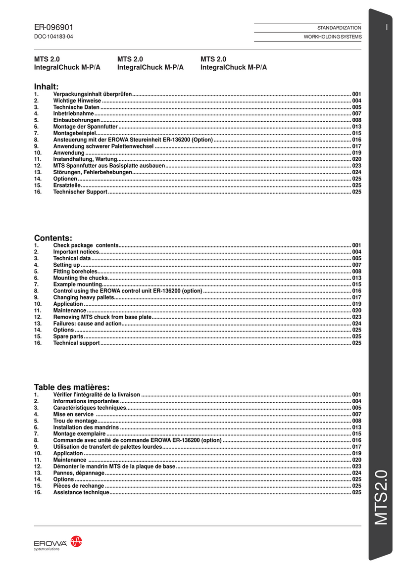
erowa MTS 2.0 IntegralChuck M-P/A User manual
erowa
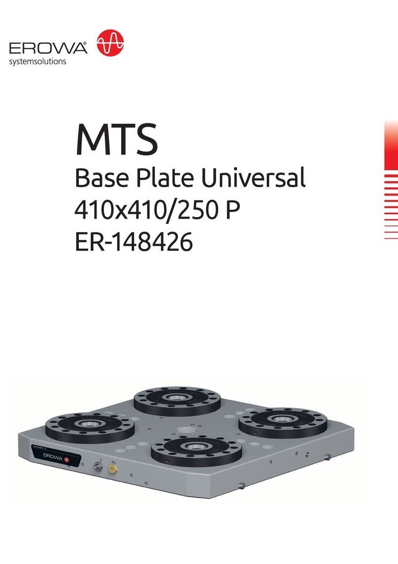
erowa ER-148426 User manual
erowa
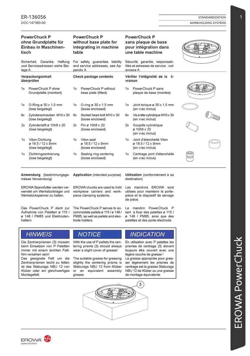
erowa PowerChuck P User manual
erowa
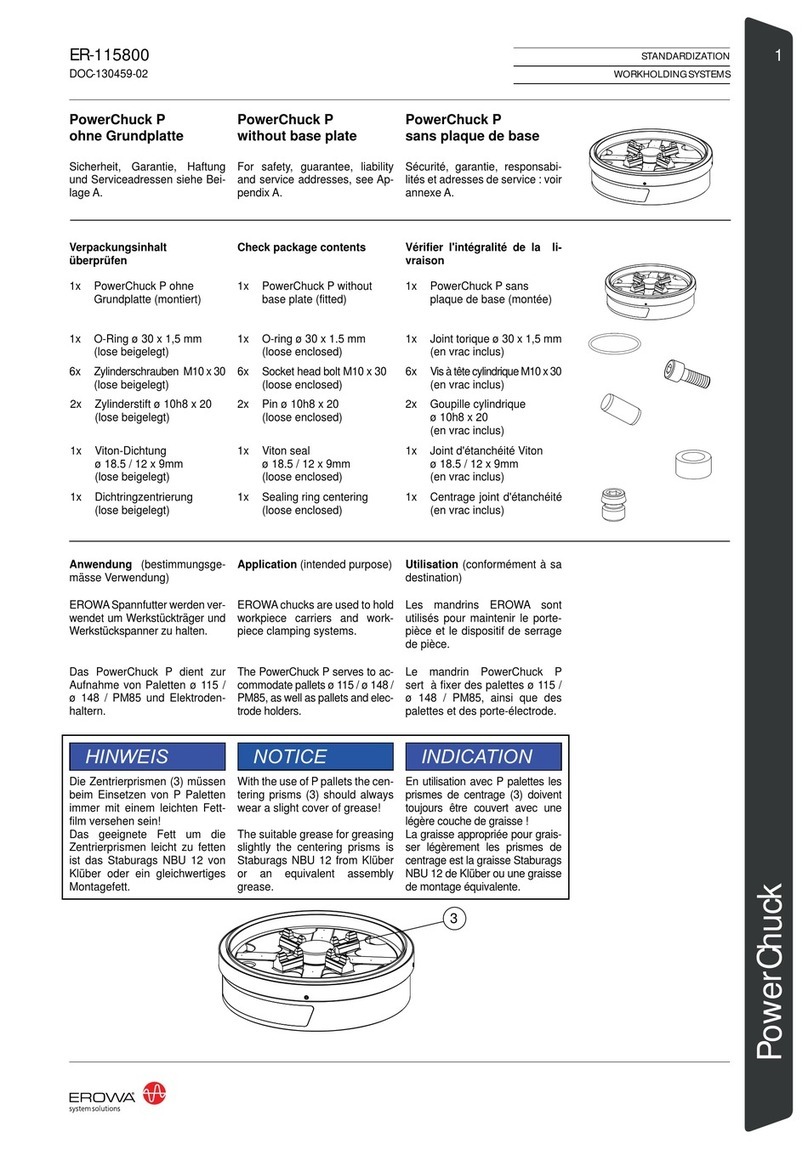
erowa PowerChuck P without base plate User manual
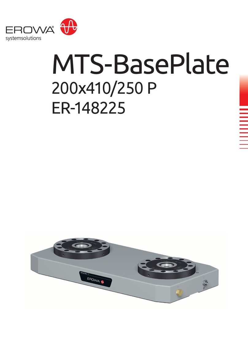
erowa
erowa MTS-BasePlate 200x410/250 P User manual

erowa
erowa MTS User manual
erowa
erowa PM85 Multi User manual
erowa
erowa ER-113300 User manual
erowa
erowa MTS IntegralChuck S-P/A User manual
erowa
erowa ER-016880 User manual
