Vega VEGATOR 636 Ex User manual

Operating Instructions
VEGATOR 636 Ex
Signal conditioning instrument
Ship approvals
Document ID: 23446

2
Contents
VEGATOR 636 Ex • Signal conditioning instrument
23446-EN-130627
Contents
1 About this document
1.1 Function ........................................................................................................................... 4
1.2 Target group ..................................................................................................................... 4
1.3 Symbolism used............................................................................................................... 4
2 For your safety
2.1 Authorised personnel ....................................................................................................... 5
2.2 Appropriate use................................................................................................................ 5
2.3 Warning about incorrect use............................................................................................. 5
2.4 General safety instructions............................................................................................... 5
2.5 CE conformity................................................................................................................... 5
2.6 Safety instructions for Ex areas ........................................................................................ 6
2.7 Environmental instructions ............................................................................................... 6
3 Product description
3.1 Conguration.................................................................................................................... 7
3.2 Principle of operation........................................................................................................ 8
3.3 Adjustment ....................................................................................................................... 8
3.4 Packaging, transport and storage..................................................................................... 8
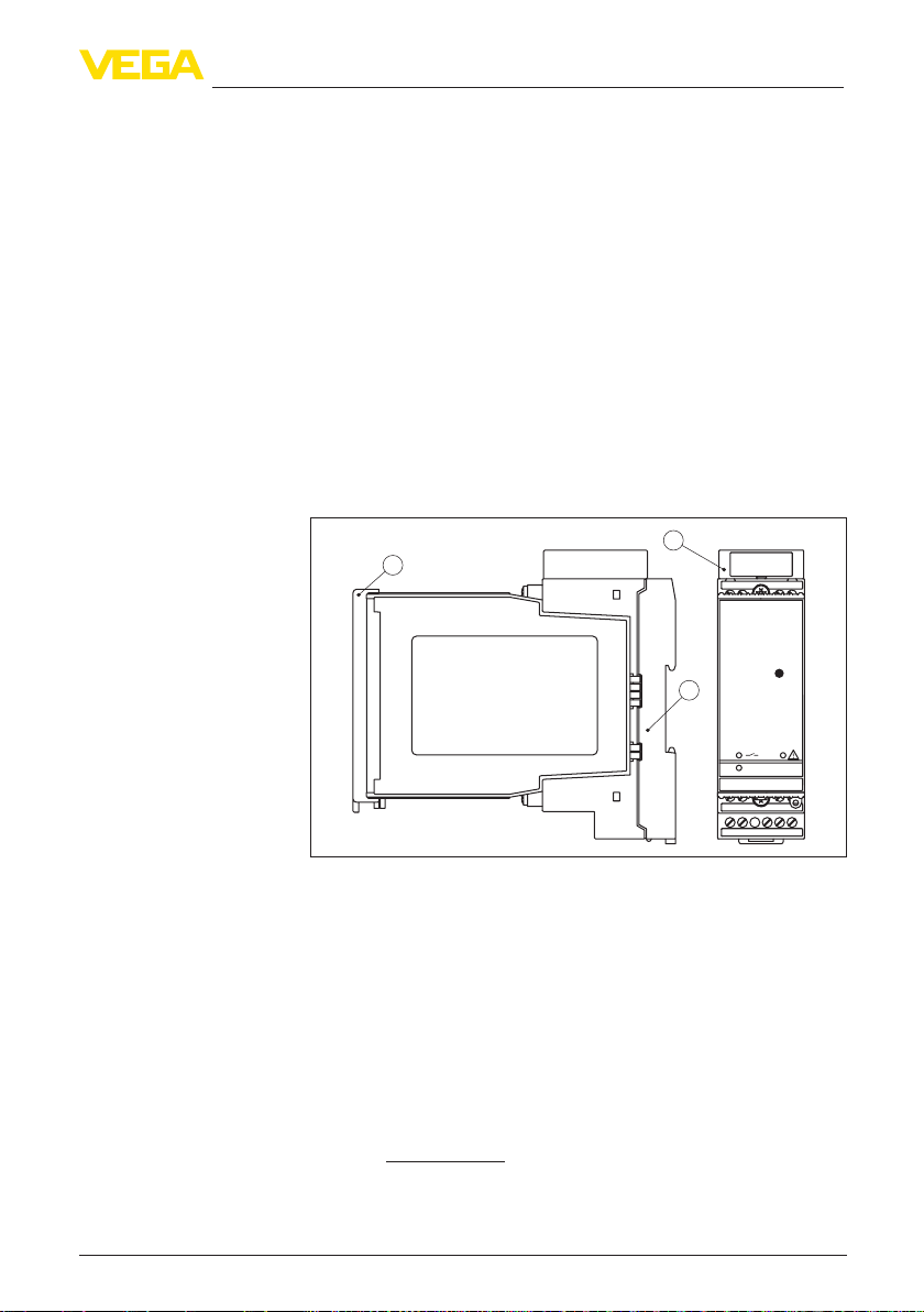
4 Mounting
4.1 General instructions ....................................................................................................... 10
4.2 Mounting instructions ..................................................................................................... 10
5 Connecting to power supply
5.1 Preparing the connection ............................................................................................... 13
5.2 Connection procedure.................................................................................................... 13
5.3 Wiring plan ..................................................................................................................... 14
6 Setup
6.1 Adjustment system......................................................................................................... 15
6.2 Adjustment elements...................................................................................................... 16
6.3 Function chart ................................................................................................................ 19
7 Maintenanceandfaultrectication
7.1 Maintenance .................................................................................................................. 21
7.2 Rectify faults................................................................................................................... 21
7.3 Instrument repair ............................................................................................................ 23
8 Dismounting
8.1 Dismounting steps.......................................................................................................... 24
8.2 Disposal ......................................................................................................................... 24
9 Supplement
9.1 Technical data ................................................................................................................ 25
9.2 Dimensions .................................................................................................................... 27

3
Contents
VEGATOR 636 Ex • Signal conditioning instrument
23446-EN-130627
Supplementary documentation
Information:
Supplementary documents appropriate to the ordered version come
withthedelivery.Yo u canndthemlistedinchapter"Product descrip-
tion".
Editing status: 2012-04-12

4
1 About this document
VEGATOR 636 Ex • Signal conditioning instrument
23446-EN-130627
1 About this document
1.1 Function
This operating instructions manual provides all the information you
need for mounting, connection and setup as well as important instruc-
tionsformaintenanceandfaultrectication.Pleasereadthisinforma-
tion before putting the instrument into operation and keep this manual
accessible in the immediate vicinity of the device.
1.2 Target group
This operating instructions manual is directed to trained specialist
personnel. The contents of this manual should be made available to
these personnel and put into practice by them.
1.3 Symbolism used
Information, tip, note
This symbol indicates helpful additional information.
Caution: If this warning is ignored, faults or malfunctions can result.
Warning: If this warning is ignored, injury to persons and/or serious
damage to the instrument can result.
Danger: If this warning is ignored, serious injury to persons and/or
destruction of the instrument can result.
Ex applications
This symbol indicates special instructions for Ex applications.
•List
The dot set in front indicates a list with no implied sequence.
→ Action
This arrow indicates a single action.
1 Sequence of actions
Numbers set in front indicate successive steps in a procedure.
Battery disposal
This symbol indicates special information about the disposal of bat-
teries and accumulators.

5
2 For your safety
VEGATOR 636 Ex • Signal conditioning instrument
23446-EN-130627
2 For your safety
2.1 Authorised personnel
All operations described in this operating instructions manual must
be carried out only by trained specialist personnel authorised by the
plant operator.
During work on and with the device the required personal protective
equipment must always be worn.
2.2 Appropriate use
VEGATOR 636 Ex is a universal signal conditioning instrument for
connection of a level switch.
Yo u cannddetailedinformationontheapplicationrangeinchapter
"Product description".
Operational reliability is ensured only if the instrument is properly
usedaccordingtothespecicationsintheoperatinginstructions
manual as well as possible supplementary instructions.
For safety and warranty reasons, any invasive work on the device
beyond that described in the operating instructions manual may be
carried out only by personnel authorised by the manufacturer. Arbi-
traryconversionsormodicationsareexplicitlyforbidden.
2.3 Warning about incorrect use
Inappropriate or incorrect use of the instrument can give rise to
application-specichazards,e.g.vesseloverllordamagetosystem
components through incorrect mounting or adjustment.
2.4 General safety instructions
This is a high-tech instrument requiring the strict observance of stand-
ard regulations and guidelines. The user must take note of the safety
instructionsinthisoperatinginstructionsmanual,thecountry-specic
installation standards as well as all prevailing safety regulations and
accident prevention rules.
Theinstrumentmustonlybeoperatedinatechnicallyawlessand
reliable condition. The operator is responsible for trouble-free opera-
tion of the instrument.
During the entire duration of use, the user is obliged to determine the
compliance of the necessary occupational safety measures with the
current valid rules and regulations and also take note of new regula-
tions.
2.5 CE conformity
ThisdevicefulllsthelegalrequirementsoftheapplicableECguide-
lines.ByattachingtheCEmark,VEGAprovidesaconrmationof
successfultesting.Yo u canndtheCEconformitydeclarationinthe
downloadareaof"www.vega.com".

6
2 For your safety
VEGATOR 636 Ex • Signal conditioning instrument
23446-EN-130627
2.6 Safety instructions for Ex areas
PleasenotetheEx-specicsafetyinformationforinstallationandop-
eration in Ex areas. These safety instructions are part of the operating
instructions manual and come with the Ex-approved instruments.
2.7 Environmental instructions
Protection of the environment is one of our most important duties.
That is why we have introduced an environment management system
with the goal of continuously improving company environmental pro-
tection.Theenvironmentmanagementsystemiscertiedaccording
to DIN EN ISO 14001.
Pleasehelpusfulllthisobligationbyobservingtheenvironmental
instructions in this manual:
•Chapter"Packaging, transport and storage"
•Chapter"Disposal"

7
3 Product description
VEGATOR 636 Ex • Signal conditioning instrument
23446-EN-130627
3 Product description
3.1 Conguration
The scope of delivery encompasses:
•VEGATOR 636 Ex signal conditioning instrument
•Terminal socket
•Bridges (4 pieces)
•Coded pins (2 pieces)
•Ex label
•Ex separating chamber
•Documentation
– this operating instructions manual
– Ex-specic"Safety instructions"(withExversions)
– ifnecessary,furthercerticates
The VEGATOR 636 Ex consists of:
•VEGATOR 636 Ex signal conditioning instrument
56 78
910121314
TEST
on
3
1
2
Fig. 1: VEGATOR 636 Ex
1 Ex separating chamber with Ex version
2 Terminal socket
3 Transparent cover
Thenameplatecontainsthemostimportantdataforidenticationand
use of the instrument:
•Article number
•Serial number
•Technical data
•Article numbers, documentation
The serial number allows you to access the delivery data of the instru-
mentvia"www.vega.com","VEGA Tools"and"serial number search".
Scope of delivery
Constituent parts
Type plate

8
3 Product description
VEGATOR 636 Ex • Signal conditioning instrument
23446-EN-130627
3.2 Principle of operation
VEGATOR 636 Ex is a single signal conditioning instrument for pro-
cessing of vibrating level switches.
The VEGATOR 636 Ex signal conditioning instrument powers con-
nected sensors and simultaneously processes their measuring
signals.
When the medium reaches the switching point of the sensor, the volt-
age on the sensor drops. The output relays then switch according to
the set mode.
Wide-range power supply unit with 20 … 253 V AC/DC for world-wide
use.
Detailed information about the power supply can be found in chapter
"Technical data".
3.3 Adjustment
The switching delay and the mode (A/B) can be preset on the signal
conditioning instrument via a DIL switch block.
A test key is lowered on the front plate of VEGATOR 636 Ex. When
pushing the key, the measuring system is checked on correct function.
3.4 Packaging, transport and storage
Your instrument was protected by packaging during transport. Its
capacity to handle normal loads during transport is assured by a test
based on ISO 4180.
The packaging of standard instruments consists of environment-
friendly, recyclable cardboard. For special versions, PE foam or PE
foil is also used. Dispose of the packaging material via specialised
recycling companies.
Transport must be carried out under consideration of the notes on the
transport packaging. Nonobservance of these instructions can cause
damage to the device.
The delivery must be checked for completeness and possible transit
damage immediately at receipt. Ascertained transit damage or con-
cealed defects must be appropriately dealt with.
Up to the time of installation, the packages must be left closed and
stored according to the orientation and storage markings on the
outside.
Unless otherwise indicated, the packages must be stored only under
the following conditions:
•Not in the open
•Dry and dust free
•Not exposed to corrosive media
•Protected against solar radiation
•Avoiding mechanical shock and vibration
Application area
Functional principle
Voltage supply
Packaging
Transport
Transport inspection
Storage

9
3 Product description
VEGATOR 636 Ex • Signal conditioning instrument
23446-EN-130627
•Storageandtransporttemperatureseechapter"Supplement -
Technical data - Ambient conditions"
•Relative humidity 20 … 85 %
Storage and transport
temperature

10
4 Mounting
VEGATOR 636 Ex • Signal conditioning instrument
23446-EN-130627
4 Mounting
4.1 General instructions
VEGATOR 636 Ex signal conditioning instrument with plug-in socket
for mounting on carrier rail according to EN 50022.
The front plate of VEGATOR 636 Ex can be provided with a lead-seal-
able transparent cover to protect the instrument against unauthorised
orinadvertentadjustment.Seethefollowinggureonhowtoremove
the transparent cover.
Fig. 2: Removing the transparent cover
For moisture-protected mounting outside the switching cabinet, we
oeraninsulatedprotectivehousingwithtransparentcover(IP65)for
surface mounting.
In this housing you can mount a maximum of 3 instruments of 36 mm
width.
4.2 Mounting instructions
The plug-in socket is constructed for carrier rail mounting according
to EN 50022. Operating voltage is connected to terminals 9 and 10.
For neighbouring signal conditioning instruments, it is possible to
continue connection L1 and N directly via the supplied bridges.
Danger:
The bridges must never be used with single instruments or at the end
of a row of instruments. If this rule is not heeded, there is a danger
of coming into contact with the operating voltage or causing a short
circuit.
A VEGATOR 636 Ex in Ex version is an auxiliary, intrinsically safe
instrument and may not be installed in explosion-endangered areas.
Installation place
Transparent cover
Housing IP 65
Installation

11
4 Mounting
VEGATOR 636 Ex • Signal conditioning instrument
23446-EN-130627
Before setup, the Ex separating chamber must be attached (as shown
below) with Ex versions. Safe operation can be only ensured if the
operatinginstructionsmanualandtheEGtypeapprovalcerticate
are observed. VEGATOR 636 Ex must not be opened.
Close the upper terminals according to the following illustration.
12 43
Fig. 3: Mounting the separating chamber
Allsignalconditioninginstrumentsareprovidedwithdierentgaps
dependent on type and version (mechanical coding).
The plug-in socket is provided with coded pins that can be inserted to
prevent accidental interchanging of the various instrument types.
With a VEGATOR 636 Ex in Ex version, the supplied coded pins (type
coded pin and Ex coded pin) must be inserted by the user according
to the below chart.
Ex separating chamber
Instrument coding

12
4 Mounting
VEGATOR 636 Ex • Signal conditioning instrument
23446-EN-130627
Typ 600-1
56 78
141312109
4321
EEx ia
+
-
L1
N
DISBUS
0...10V
9
8
7
3
2
1
C
B
A
12
Plug-in socket
2
1
3
4
Fig. 4: Plug-in socket VEGATOR 636 Ex
1 Bridges for looping the operating voltage
2 Type coding for VEGATOR 636 Ex
3 Ex coding with Ex version
4 Ex separating chamber

13
5 Connecting to power supply
VEGATOR 636 Ex • Signal conditioning instrument
23446-EN-130627
5 Connecting to power supply
5.1 Preparing the connection
Always keep in mind the following safety instructions:
•Connect only in the complete absence of line voltage
•If overvoltage surges are expected, overvoltage arresters should
be installed
Tip:
We recommend VEGA overvoltage arresters B61-300 (power supply
VEGATOR 636 Ex) and B62-36G (sensor supply).
Inhazardousareasyoumusttakenoteoftherespectiveregulations,
conformityandtypeapprovalcerticatesofthesensorsandpower
supply units.
Thepowersupplycanbe20…250VAC,50/60Hzor20…72VDC.
The operating voltage of VEGATOR 636 Ex is connected with stand-
ard cable according to the national installation standards.
The sensors are connected with standard two-wire cable without
screen. If electromagnetic interference is expected which is above the
test values of EN 61326 for industrial areas, screened cable should
be used.
Connect the cable screen on both ends to ground potential. In the
sensor, the screen must be connected directly to the internal ground
terminal. The ground terminal on the outside of the sensor housing
must be connected to the potential equalisation (low impedance).
If potential equalisation currents are expected, the connection on the
processing side must be made via a ceramic capacitor (e. g. 1 nF,
1500 V). The low-frequency potential equalisation currents are thus
suppressed,buttheprotectiveeectagainsthighfrequencyinterfer-
ence signals remains.
Take note of the corresponding installation regulations for Ex applica-
tions. In particular, make sure that no potential equalisation currents
owoverthecablescreen.Incaseofgroundingonbothsidesthis
can be achieved by the use of a capacitor or a separate potential
equalisation.
5.2 Connection procedure
Move on to electrical connection and proceed as follows:
1. Snap the socket without VEGATOR 636 Ex onto the carrier rail
2. Connect sensor cable to terminal 1 and 2, and where applicable,
connect the screen
3. Connectpowersupply(switchedo)toterminal9and10
4. Insert VEGATOR 636 Ex into the plug-in socket and screw it down
tightly
Theelectricalconnectionishencenished.
Note safety instructions
Take note of safety
instructions for Ex
applications
Select power supply
Select connection cable
Cable screening and
grounding
Select connection
cable for Ex applica-
tions

14
5 Connecting to power supply
VEGATOR 636 Ex • Signal conditioning instrument
23446-EN-130627
Before setting up Ex versions, make sure the Ex separating chamber
is plugged (above the sensor terminals). The pins for type and Ex
coding must also be inserted correctly.
5.3 Wiring plan
3
5 4
1
2
5 6 7 8
1 2 3 4
9 10 12 13 14
+ -
+-
+
L1 N
-
Fig. 5: Wiring plan VEGATOR 636 Ex
1 Sensor
2 Sensor input
3 Transistor output
4 Relay output
5 Operating voltage

15
6 Setup
VEGATOR 636 Ex • Signal conditioning instrument
23446-EN-130627
6 Setup
6.1 Adjustment system
Typ 600-1
on
56 78
910121314
56 78
141312109
4321
TEST
EEx ia
+
-
L1
N
DISBUS
0...10V
9
8
7
3
2
1
C
B
A
12
Plug-in socket
6
5
10
7
7
8
9
1
2
3
4
Fig. 6: Display and adjustment elements
1 Test key
2 Control lamp - level relay (LED yellow)
3 Control lamp - Fault signal (LED red)
4 Control lamp - Operating voltage (LED green)
5 Ex separating chamber
6 Terminal for probe
7 Sockets for bridges
8 Transistor output
9 Relay output
10 Voltage supply

16
6 Setup
VEGATOR 636 Ex • Signal conditioning instrument
23446-EN-130627
123456
12
6
2
ze
za
AB
off
t sec
IP 30
Sensorstromkreis EEx ia IIC
60mA
-
+
-
+
PTB-Nr.: Ex-95/xxxx X
max: 36V
56
nsp.I
a: -20...+60°C
power supply
20...72VDC
2 W
20...250 VAC
LN
Sensor
12
Terminal
1312
out
14
3AAC/1ADC
500VA/54W
max.250VAC/DC
910
+-
Uo< xx VL
o< xx mH
Co < xx nF
Po< xx mW
Io< xx mA
1
23
Fig. 7: Display and adjustment elements
1 DIL switch block
2 Type plate
3 Transparent cover
6.2 Adjustment elements
Control lamps (LED) in the front plate indicate operation, switching
status and fault signal.
•Green
– Operating control lamp
– Mains voltage on, instrument is operating
•Red
– Failure lamp
– Fault on the sensor circuit due to sensor failure or line break
– The relay deenergises in case of failure
•Yellow
Control lamps

17
6 Setup
VEGATOR 636 Ex • Signal conditioning instrument
23446-EN-130627
– Relay control lamp
– The yellow relay control lamp reacts depending on the set
mode (A/B)
– The relay control lamp generally indicates the activated (ener-
gized)conditionoftherelay
– A dark relay control lamp means that the relay is deenergised
(transistor blocks)
Laterally on top (covered when mounted) there is a DIL switch block
with six switches. The individual switches are assigned as follows:
•1 - A/B mode
– A-Max.detectionoroverowprotection
– B - Min. detection or dry run detection
•2-Switchodelay(za)
•3-Switchondelay(ze)
•4 - Switching delay 2 s
•5 - Switching delay 6 s
•6 - Switching delay 12 s
Withswitch1youcanadjustthemode(A-overllprotectionorB-
dry run protection).
Withswitches2and3youcansetswitchoand/orswitchondelays
independent of each other.
The delay refers to the switching function of the relay.
In the example (see previous illustration), mode A (max. detection of
overllprotection)isselected(switch1).Theswitchodelayisacti-
vated (switch 2) and the switching delay is set to 8 seconds (switch 4,
5 and 6).
With switches 4, 5 and 6 you can adjust the switching delay. The times
oftheactivatedtimeswitchesaccumulate.Iftheswitchon(ze)and
switchodelay(za)areswitchedontogether,thesettimeappliesto
both delay modes.
Hence the relay deenergises with 8 seconds delay time when the
switching point is reached.
Information:
Keep in mind that the switching delay of the sensor and signal condi-
tioning instrument accumulate.
Switch 1 2 3 4 5 6
Time za ze 2 s 6 s 12 s
0.2 s A/B o o o o o
0.5 s A/B 1) o o o
2 s A/B on o o
6 s A/B o on o
8 s A/B on on o
12 s A/B o o on
DIL switch block
1) Setalternatelyswitch2and/or3to"on".Thetimesapplytotheadjusted
delay mode.

18
6 Setup
VEGATOR 636 Ex • Signal conditioning instrument
23446-EN-130627
Switch 1 2 3 4 5 6
14 s A/B on o on
18 s A/B o on on
20 s A/B on on on
The measuring system is continuously monitored. The following
criteria are checked:
•Two-wire cable on line break and shortcircuit
•Interruptionoftheconnectioncabletothepiezoelements
•Corrosion or damage of the tuning fork (vibrating rod)
•Break of the tuning fork (vibrating rod)
•Loss of vibration
•Too low vibrating frequency
•Medium penetrating from the vessel side into the sensor
In systems with VEGASWING or VEGAVIB level switches in conjunc-
tion with a two-wire electronics module, a function test can be carried
out. VEGATOR 636 Ex has an integrated test key. The test key is
recessed in the front plate of the signal conditioning instrument. Push
the test key with a suitable object (e.g. screwdriver, pen etc.).
By pushing the key, the system is checked on the following criteria:
•Switching function of the switching outputs
•Potential separation of the outputs
•The signal processing of the signal conditioning instrument
After pushing the test key, the complete measuring system is checked
on correct function. The following operating conditions are simulated
during the test:
•Fault message
•Empty signal
•Full signal
Check if all three switching conditions occur in the correct sequence
and the stated duration. If not, there is a fault in the measuring system
(seechapter"Fault rectication").
Note:
Keep in mind that the connected instruments are activated during the
function test. By doing this, you can check the correct function of the
measuring system.
After releasing the key.
Thespeciedtimesapplywithatoleranceof±20%.
A-mode B-mode
1 Simulation of a fault signal (approx. 3 s)
Level relay deenergised Relaycontrollampo Relaycontrollampo
1 Simulation of a fault signal
Failure lamp Failure lamp lights Failure lamp lights
Function monitoring
Test key
Test procedure

19
6 Setup
VEGATOR 636 Ex • Signal conditioning instrument
23446-EN-130627
A-mode B-mode
2 Simulation an empty signal (approx. 1.5 s)
Level relay energised Relay control lamp lights Relaycontrollampo
2 Simulation of an empty signal
Failure lamp Failurelampo Failurelampo
3 Simulation of a full signal (approx. 1.5 s)
Level relay deenergised Relaycontrollampo Relay control lamp lights
3 Simulation of a full signal
Failure lamp Failurelampo Failurelampo
4 Return to the current operating condition (covered/
uncovered)
Check the process of the function test. Take the following criteria into
account for evaluation of the result:
Test passed
If all three switching conditions occur in the correct sequence and the
speciedduration(±20%),thenthetestispassedandtheinstrument
functions correctly.
Test not passed
•Thespeciedtimesdeviateconsiderablyfromthetable(>3s)
•One of the switching conditions remains unchanged
•No start-up of the test - no signal sequence
6.3 Function chart
The following chart provides an overview of the switching conditions
depending on the set mode and the level.
The mode switch on the sensor (if available) must be set to max.
operation.
Sensor (max. opera-
tion)
Signal conditioning instrument
Mode on
the signal
condi-
tioning
instrument
Level Signal
current -
Sensor
Sig-
nal lamp
- Switch-
ing output
(yellow)
Con-
trol lamp
- Failure
(red)
Outputs
Mode A
Overow
protection
approx.
8 mA
Relay ener-
gized
transistor
conducts
Mode A
Overow
protection
approx.
16 mA
Relay de-
energized
transistor
blocks
Evaluation

20
6 Setup
VEGATOR 636 Ex • Signal conditioning instrument
23446-EN-130627
Sensor (max. opera-
tion)
Signal conditioning instrument
Mode on
the signal
condi-
tioning
instrument
Level Signal
current -
Sensor
Sig-
nal lamp
- Switch-
ing output
(yellow)
Con-
trol lamp
- Failure
(red)
Outputs
Mode B
Dry run
protection
approx.
16 mA
Relay ener-
gized
transistor
conducts
Mode B
Dry run
protection
approx.
8 mA
Relay de-
energized
transistor
blocks
Fault mes-
sage
(mode A/B)
any approx.
1.8 mA
Relay de-
energized
transistor
blocks
Table of contents
Other Vega Industrial Equipment manuals

Vega
Vega PLICSMOBILE Series User manual

Vega
Vega VEGALOG 571 AT User manual

Vega
Vega VEGAPULS 6X User manual

Vega
Vega VEGASON 64 User manual

Vega
Vega VEGASOURCE 85 User manual

Vega
Vega VEGASOURCE 86 User manual

Vega
Vega VEGATOR 256C User manual

Vega
Vega SHLD1 User manual

Vega
Vega VEGASOURCE 82 User manual

Vega
Vega VEGABAR 82 User manual
Popular Industrial Equipment manuals by other brands

Huawei
Huawei FusionModule1000A40 ICT Solution Quick installation guide

American Lubrication Equipment
American Lubrication Equipment TIM-390-A1 manual

Fastbind
Fastbind C400 user manual

Eaton
Eaton NZM3-XK22 21 Series Instruction leaflet

CNC FACTORY
CNC FACTORY VIPER user guide

Forum
Forum BOP AT 300 MkII Operation & maintenance manual