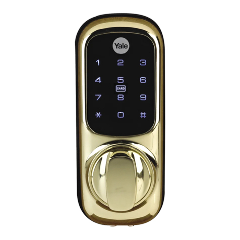
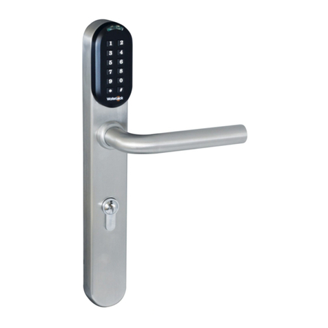
BioAxxis BD-1 User manual

http://www.BioAxxis.com
BioAxxis® BD1
1
PREFACE
Thank you for purchasing the BioAxxis® BD-1
fingerprint dead olt.
Please read the documentation carefully efore
installation & use. The manual details all
installation procedures and operation steps.
Manufacturer and/or Distri utors of the BioAxxis®
BD1 will not e responsi le for any damages caused
y incorrect installation or mishandling of the lock.
Any such damages will void manufacturer’s
warranty.

http://www.BioAxxis.com
BioAxxis® BD1
2
Ta le of Contents
Preface………………………………………………………………1
Installation Manual
1. Parts ........................................................................................ 3
2. Required Tools........................................................................ 4
3. Pre installation........................................................................ 5
3.1 Mark and bore holes on the door .................................. 5
3.2 Deadbolt Latch Selection.............................................. 9
4. Installation ............................................................................ 10
4.1 Installation of Deadbolt .............................................. 10
4.2 Installing Strike and Strike Lining Box (on the door
jamb) ................................................................................. 11
4.3 Sizing Tail Piece (to the right length)......................... 12
4.4 Installation of the Outdoor Unit.................................. 14
4.5 Installation of the Indoor Unit .................................... 16
5. Trouble Shooting .................................................................. 23
Operation Manual ..................................................................... 25
Section I Enrolling Administrators (First 2 Fingerprint
Users):............................................................................... 28
Section II Enrolling Fingerprint Users 3 thru 30:........... 33
Section III – Deleting Individual Fingerprint Users:........ 36
Section IV – Deleting ALL Fingerprint Users: ................ 39
Section V – Unlocking the BioAxxis® BD1 from outside:
.......................................................................................... 41
Section VI – Locking the BioAxxis® BD1 from Outside:
.......................................................................................... 43
Section VII – Locking and Unlocking the BioAxxis® BD1
from Inside:....................................................................... 44
USER ENROLLMENT TABLE: ..................................... 45

http://www.BioAxxis.com
BioAxxis® BD1
3
1. Parts
Please familiarize yourself with all the parts in the packaging box of
the BioAxxis® BD1. If any part is missing or damaged, contact our
service center or your local dealer.
Outdoor Unit
Indoor Unit
Strike Lining Box
Outdoor Rubber Gasket
Strike Plate
Keys
D
eadbolt Latch
2 ¾” backset (70mm)
Deadbolt Latch
2 3/8” backset (60mm)
Screws (82 mm)

http://www.BioAxxis.com
BioAxxis® BD1
4
Screws
(2 x 40 mm & 1 x 29mm)
Wooden & Metal
Screws
Alkaline
Batteries
2. Required Tools
① Electric or battery operated Drill
② One 3/8” Diameter Drill Bit
③ One 1” Diameter Drill bit
④ One 2 1/8” Diameter Drill Bit
⑤ A Carpenter Chisel
⑥ A Hammer
⑦ A pair of scissors
⑧
⑧⑧
⑧ Vise Grip
⑨ Philips & flat head screw drivers
⑩
⑩⑩
⑩
Metal Cutters or Hacksaw
11) Marker

http://www.BioAxxis.com
BioAxxis® BD1
5
3. Pre-installation
3.1 Mark and ore holes on the door
3.11 Mark holes on door
For doors with existing deadbolt lock with 2 1/8” diameter hole:
1) Remove existing cylindrical deadbolt .
2) Please be sure to use the installation
template when installing the
BioAxxis® BD1 on a door with an
existing deadbolt.

http://www.BioAxxis.com
BioAxxis® BD1
6
3) Cut out the two, 3/8” holes on the
Installation Template that correspond
to your existing backset (2 3/8” or 2
¾”).
4) Rest the installation template on the
front of the door, on top of the
existing 2 1/8” hole, making sure that
it is aligned properly for the door’s
existing 2 3/8” or 2 ¾” backset.
5) Mark the two, 3/8” holes that you cut
out of the installation template on the
door (with a magic marker).

http://www.BioAxxis.com
BioAxxis® BD1
7
6) Bore the two, 3/8” holes into the door
(using a 3/8” drill bit), making sure
that the holes fully penetrate through
the door.
7) Go to Section 4.3 in the User Manual

http://www.BioAxxis.com
BioAxxis® BD1
8
For doors that do not ha e a cylindrical deadbolt lock or a hole for
the cylindrical deadbolt lock:
A. Start approximately 46” from
floor. Select the appropriate
installation template
according to the length of the
backset. Fold and apply the
template to the edge of the
door bevel. Mark the center
point of the cylinder hole on
the door face, and then mark
the center point of the
deadbolt hole on door edge,
as indicated on the template.
B. For installation of
combination set (door handle
and deadbolt), it is
recommended that the
distance is 5 ½” between the
two center points.
C. Mark the center points of the
two small holes on the door
face for the two upper fixing
posts mounted on the top
plate of the outdoor unit, as
indicated on the installation
template.

http://www.BioAxxis.com
BioAxxis® BD1
9
3.12 Bore holes
A. Bore a 2 1/8” diameter hole in the
center of door face for chassis. (It is
recommended to bore this hole from
both sides of the door to avoid
splintering.)
B. Bore a 1” diameter hole in the center
of door edge for deadbolt.
C. Bore two separate 3/8” diameter
holes for the upper fixing posts.
3.2 Dead olt Latch Selection
There are two deadbolt latches in each box, one with a 2 3/8”
(60mm) backset and the other with a 2 ¾” (70mm) backset. Make
sure which length you will need and select the right one before
installation.

http://www.BioAxxis.com
BioAxxis® BD1
10
4. Installation
4.1 Installation of Dead olt
A.
Insert the deadbolt latch into the hole
in the edge of the door (follow the UP
sign), keeping it parallel to the face of
the door. Mark the outline of the face
plate and remove the deadbolt.
B.
Then chisel 1/8” deep rectangular
shape, per your marking (or until the
faceplate is flush with the door edge).
C.
Insert the deadbolt latch; make sure
the deadbolt UP sign is facing
upwards. Then fasten the screws.

http://www.BioAxxis.com
BioAxxis® BD1
11
4.2 Installing Strike and Strike Lining Box
(on the door jam )
A.
(1)
Close the door until the
deadbolt touches the door
jamb along the face plate
to mark the horizontal
center lines.
(2)
Measure one half of the
door thickness from one
side of the door jamb,
and then mark the
vertical center lines.
(3)
Extend the vertical center
line and the horizontal
line to mark the drill
center point for the strike.
B.
Bore a 1” diameter and 1”
deep hole in the door jamb at
the center point for strike. To
ensure the proper deadbolt
function, this hole must be
drilled at least 1” deep.
C.
Chisel the door jamb at 1/16”
deep for the strike plate which
must fit flush with the door
jamb.
D.
Insert the strike lining box
and then fasten screws to the
plate.

http://www.BioAxxis.com
BioAxxis® BD1
12
4.3 Sizing Tail Piece (to the right length)
The BioAxxis® BD1 is designed to fit door thicknesses of 1 3/8” to
2”.
Four pre sized tailpieces are included with the BioAxxis® BD1 for 1
3/8”, 1 ½”, 1 ¾” and 2” thick doors.
Your door thickness and length of the tailpiece being used must
match exactly. EX: If your door is 1 ¾” thick, then you must use the
1 ¾” long tailpiece.
The BioAxxis® BD1 comes with the 1 ¾” tailpiece pre installed. If
your door is not 1 ¾” thick, but the thickness matches one of the
other pre cut tailpieces included with the lock, then you must swap
out the tailpiece.
For video directions on how to swap the tailpiece, go to the
BioAxxis® BD1 product page at www.BioAxxis.com and click on
the Support Material section on the bottom of the page for links to
the instructional videos.

http://www.BioAxxis.com
BioAxxis® BD1
13
IF YOUR DOOR THICKNESS DOES NOT EXACTLY
MATCH ANY OF THE PRE-CUT TAILPIECES LENGTHS,
THEN YOU MUST TRIM THE PRE-INSTALLED TAIL
PIECE TO MATCH YOUR EXACT DOOR THICKNESS
.
If you need to trim the tailpiece, be sure to measure the exact
thickness of your door, mark the tailpiece (with a marker) where it
needs to be cut and trim the tail piece accordingly per the exact
thickness of your door, with a hacksaw or metal cutters.
Notes:
The motor could be dislodged if the tailpiece is not cut properly and
is too long, due to excessive pressure.
Warranty will e voided if
this occurs.

http://www.BioAxxis.com
BioAxxis® BD1
14
4.4 Installation of the Outdoor Unit
1) Attach
th
e rubber gasket to the back
of the outdoor unit.
2) Make sure the tail piece is vertical.

http://www.BioAxxis.com
BioAxxis® BD1
15
3) Make sure the deadbolt is engaged.
4) Insert tail piece through the cross slot
of the latch.
5) Insert the connector and wire through
the cylinder hole below the deadbolt
latch.
6) Insert the two upper fixing posts
through the small upper holes on the
door (the newly drilled holes).

http://www.BioAxxis.com
BioAxxis® BD1
16
4.5 Installation of the Indoor Unit
1) Select the proper door opening
orientation on the back plate of the
Indoor Unit. If the door is left
handed, please push the orientation
selector switch to “L” position; if it’s
right handed, switch the selector to
“R” position.
Right Handed/Left Handed
2) Left handed doors are defined as
hinge on the left when you are
entering the home from outside. The
opposite is true for right handed
doors.

http://www.BioAxxis.com
BioAxxis® BD1
17
3) Plug wire set into circuit board,
making sure all prongs are firmly
seated.
4) Press sheathing of wire casing into the
wire holder clamp.

http://www.BioAxxis.com
BioAxxis® BD1
18
5) Turn the manual turn knob to the
vertical position, facing downward.

http://www.BioAxxis.com
BioAxxis® BD1
19
6) Insert the tail piece into the vertical
retaining slot of the indoor unit.
7) Gently finish joining the outdoor and
indoor units together, ensuring all
fixing posts are aligned properly.
8) Fasten the two shorter screws
through the upper fixing post holes on
the upper section of the inside unit.

http://www.BioAxxis.com
BioAxxis® BD1
20
9) Fasten the two long screws through
the bottom fixing post holes on the
inside unit.
10) Move the manual turn knob back
and forth to ensure that deadbolt
opens and closes mechanically.
Table of contents
