BKT Elektronik BKT AL200 User manual

BKT Elektronik - Headquarter
Poland, Lochowska 69 Str.
86-005 Biale Blota
Phone: +48 52 36 36 750
e-mail: export@bkte.pl
www.bkte.pl
BKT AL200
Electronic locking & monitoring swinghandle with
mechanical override
- user manual
Version 2
© 2021 BKT Elektronik

AL200 swinghandle manual
2
Table of contents
1Introduction................................................................................................................................................................................................3
1.1 General information ........................................................................................................................................................................3
1.2 Device characteristics ......................................................................................................................................................................3
2Technical specifications ...............................................................................................................................................................................3
3Assembly.....................................................................................................................................................................................................4
3.1 Package Contents............................................................................................................................................................................4
3.2 Dimensions......................................................................................................................................................................................4
3.2.1 Swinghandle dimensions ...................................................................................................................................................4
3.2.2 Cut out dimensions............................................................................................................................................................5
3.2.3 Cogwheel dimensions........................................................................................................................................................5
3.2.4 Cam dimensions................................................................................................................................................................5
3.3 Single point assembly ......................................................................................................................................................................6
3.4 Multi-point assembly.......................................................................................................................................................................6
3.5 Connection......................................................................................................................................................................................7
4Operation....................................................................................................................................................................................................7
4.1 Electrical opening ............................................................................................................................................................................7
4.2 Handle position indication ...............................................................................................................................................................8
4.3 Working status indication ................................................................................................................................................................8
5Accessories .................................................................................................................................................................................................8
6Document revisions.....................................................................................................................................................................................9

AL200 swinghandle manual
3
1Introduction
1.1 General information
Warning:
This is a Class A product. In a domestic environment this product may cause radio interference in which case the user may be required to take
adequate measures.
The specification is owned and copyrighted by BKT Elektronik Sp. z o.o. Information contained herein may be changed at owner’s discretion
without any notice. BKT Elektronik may not be held liable for any possible inaccuracies and discrepancies in this document.
1.2 Device characteristics
The AL200 is an electronic swinghandle for ICT cabinets. It allows opening of cabinet doors in a standard way and by electrical remote control. It
can operate with any access control system. The device has a handle position indication. Thanks to the installed cylinder, it is also possible to
open it with a key.
Basic features:
It allows the remote opening from any external access control systems.
Equipped with the optical sensor of the handle position.
Two multi-pin connectors providing control and status signals of the handle.
Three-color LED signalling the operation status of the swinghandle.
Emergency key override.
Available inserts for the master key system.
For use with indoor cabinets.
Installation in a standard 150x25mm cut out.
Can be installed in a single and multi-point locking system (requires additional elements - cam or cogwheel mechanism, which should
be ordered separately).
2Technical specifications
Parameter
Value
Power supply voltage
Nominal 12V DC, allowed 10-24V DC, recommended power supply 12V DC ≥500mA
Quiescent current consumption
110 mA at 10 V
90 mA at 12 V
60 mA at 24 V
Maximal current consumption
when opening/closing (200ms)
300 mA at 10 V
250 mA at 12 V
150 mA at 24 V
Connectors
Type 53047-0810 8-pin connector, type 53047-0410 4-pin connector
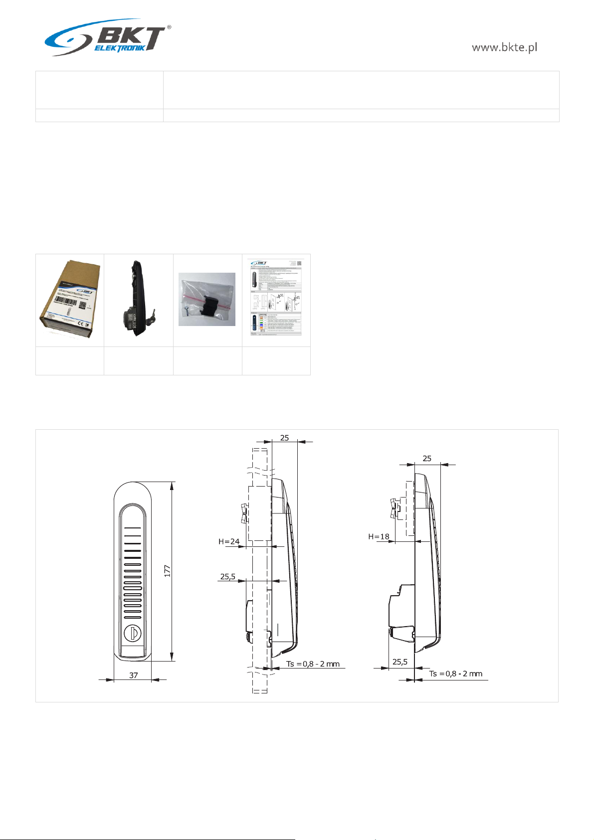
Dimensions
177 x 37 x 51mm (H x W x D)
Weight
150g
Packaging dimensions
200 x 100 x 50 mm (W x D x H)
Packaging weight
200g
Operating conditions
Temperature: 0°C - 50°C, Humidity: 0% - 90% RH (without condensation)
Storage conditions
Temperature: -10°C - 60°C, Humidity: 0% - 95% RH (without condensation)
Enclosure material
Glass fibre reinforced polyamide PA6 GF30
Enclosure colour
Black, RAL 9005
Enclosure protection degree
IP30
Compliance with directives
2014/30/EU (EMC), 2011/65/EU (RoHS)
Compliance with standards
EN 61000-4-2:2009 Electrostatic discharge immunity test.
EN 61000-4-3:2007 Radiated, radio-frequency, electromagnetic field immunity test
EN 61000-4-4:2012 Electrical fast transient/burst immunity test.
EN 61000-4-5:2014 Surge immunity test.
AL200 swinghandle manual
4
EN 61000-4-6:2014 Immunity to conducted disturbances, inducted by radio-frequency fields.
EN 61000-6-4:2007/A1:2011 Electromagnetic compatibility (EMC) –Emission standard for industrial
environments.
Part number
122AL002000
3Assembly
The swinghandle can work in a single-point system (only with a cam) or a multi-point system (with a cogwheel mechanism and a cam). The
package does not contain all the mounting elements. Additional mounting elements dedicated to the respective cabinet must be ordered
separately.
3.1 Package Contents
Packaging
AL200 swinhandle
Fastening element
with screw
Quick Start Guide
3.2 Dimensions
3.2.1 Swinghandle dimensions
AL200 swinghandle manual
5
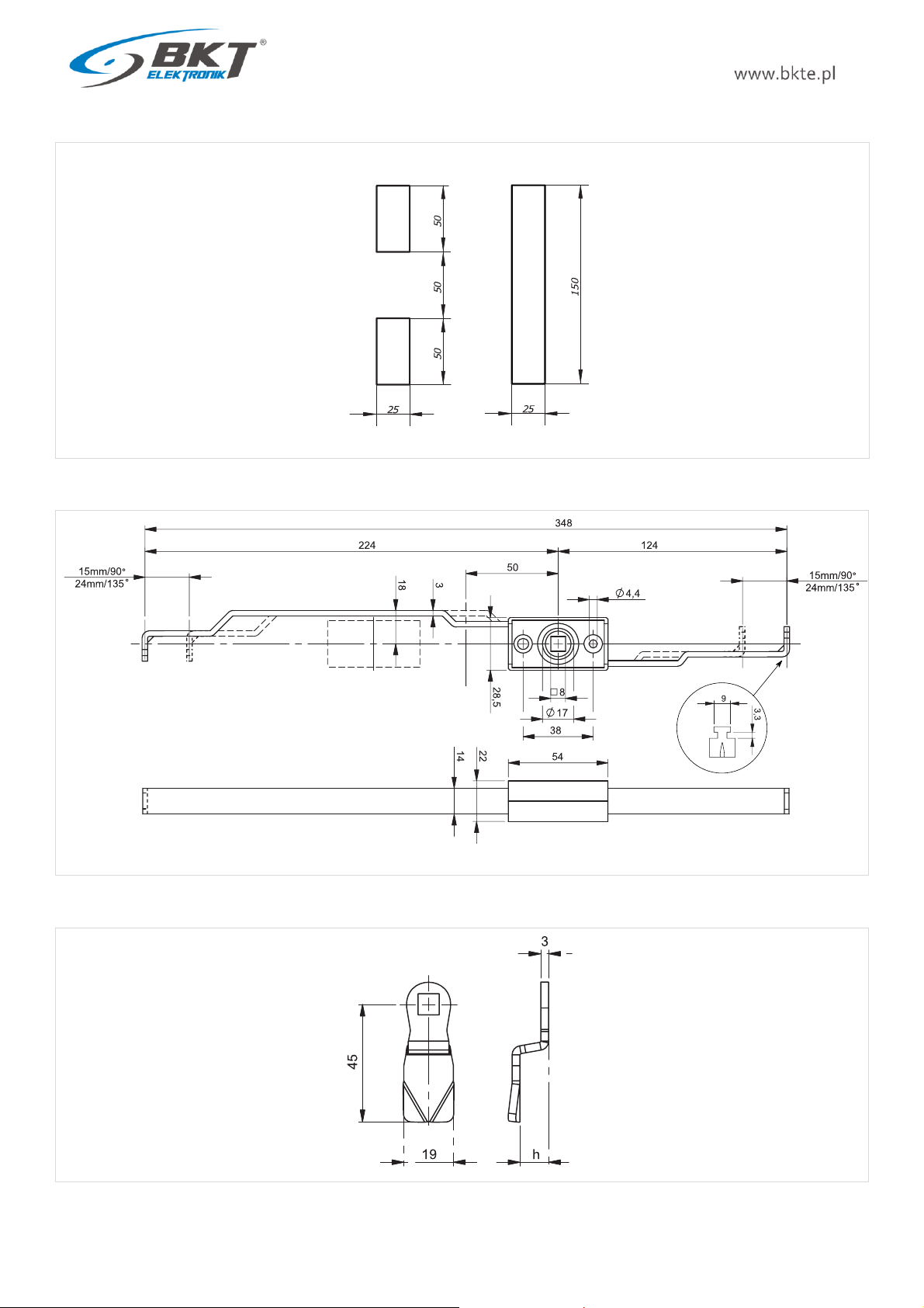
3.2.2 Cut out dimensions
3.2.3 Cogwheel dimensions
3.2.4 Cam dimensions
or
AL200 swinghandle manual
6
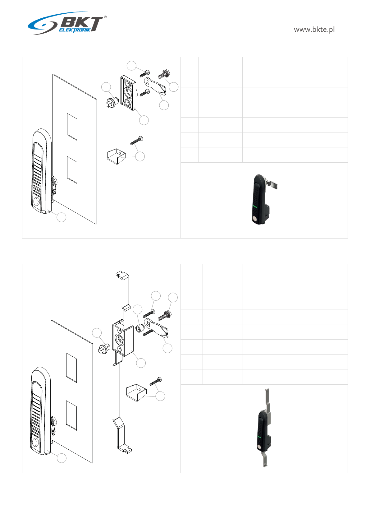
3.3 Single point assembly
1
122AL002000
AL200 swinghandle
2
Fastening element with screw
3
122AM002021
Cap
4
122AM002022
Cap adapter
5
122AM002023
Cap screw F4.1x12
6
122AM002024
Cam bolt M6x8
7
122AM002100
Cam h=0mm (locking height H=18mm)
3.4 Multi-point assembly
1
122AL002000
AL200 swinghandle
2
Fastening element with screw
3
122AM002001
Cogwheel mechanism
4
122AM002002
Cogwheel mechanism adapter
5
122AM002003
Bushing for cam
6
122AM002004
Cam bolt M6x16
7
122AM002005
Cogwheel screw F4.1x22
8
122AM002006
Cam h=0mm (locking height H=24mm)
1
2
4
3
5
7
6
1
2
4
3
6
8
7
5
AL200 swinghandle manual
7
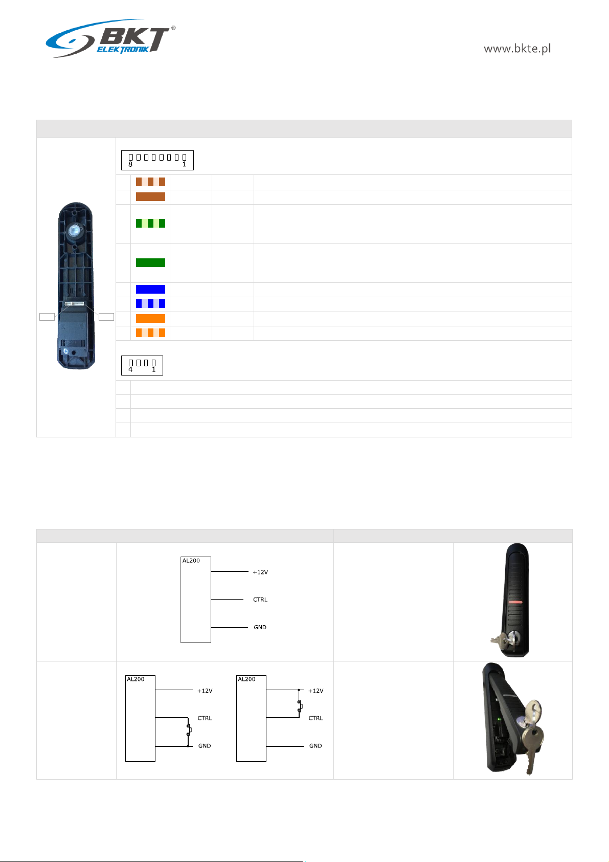
3.5 Connection
To connect the handle to external access control systems, use the AW200 or AW205 cable (see chapter 5 Accessories). The cable can be extended
to a maximum length of 100m using UTP Cat5e cable.
Connectors
Socket type 53047-0810
1
w/brown
GND
Power supply input: GND
2
brown
+12V
Power supply input: +12V DC
3
w/green
STATUS
Open collector output for signalling the position of the handle, IC=50mA, UCE=25V.
Handle open -> NPN transistor open (active)
Handle closed -> NPN transistor closed (inactive)
4
green
CTRL
Input for controlling the swinghandle from an external system.
Opening the handle -> CTRL shorted to GND or +12V
Closing the handle -> CTRL not connected
5
blue
SENSOR
Door sensor input - for the future use. Do not connect.
6
w/blue
GND
GND - for the door sensor - for the future use. Do not connect.
7
orange
CANL
CAN bus interface (CANL) - for the future use. Do not connect.
8
w/orange
CANH
CAN bus interface (CANH) - for the future use. Do not connect.
Socket type 53047-0410 for the future use. Do not connect.
1
For the future use. Do not connect.
2
For the future use. Do not connect.
3
For the future use. Do not connect.
4
For the future use. Do not connect.
4Operation
4.1 Electrical opening
Electric opening is made by shorting the CTRL input to the GND or +12V potential. If the CTRL input is not connected anywhere, then the
swinghandle remains closed.
CTRL input state
Swinghandle lock status
CTRL input not
connected
Lock is closed
CTRL input not
connected to
GND or +12V
Lock is open
PIN 1
PIN 8
or

AL200 swinghandle manual
8
4.2 Handle position indication
The device has an optical sensor of the handle position, thanks to which this information can be transferred to an external access control system.
The state of the STATUS output corresponds to the position of the handle. The STATUS output has overload protection. If the current through
the transistor is greater than 50mA, the output will be turned off. The STATUS output will return tonormal operation after removing the overload
and changing the position of the handle.
Position of the handle
STATUS output state
Handle closed
STATUS output inactive (NPN
transistor closed)
Handle open
STATUS output active (NPN
transistor open)
4.3 Working status indication
The swinghandle has a three-color LED indicating the status of its operation.
LED state
Swinghandle working state
Orange is on
The device is in programming mode
Orange blinking
The device is booting (within 3 seconds after connecting the power)
or firmware error (if it blinks for more than 3 seconds)
Red is on
The electric lock of the device is closed (no control on the CTRL input)
Red blinking
The electric lock of the device is closed (no control on the CTRL input), but the
handle is open.
Green is on
The electric lock of the handle is open (controlled on the CTRL input)
5Accessories
Product
Description
Part number
AW200 - AL200 swinghandle connection cable, length 0,5m; connectors: 1-plug, 2-ferrules
122AW002000
AW205 - AL200 swinghandle connection cable, length 5m; connectors: 1-plug, 2-ferrules
122AW002050
LED

AL200 swinghandle manual
9
6Document revisions
Version
Changes
Date
1
Initial version.
March 2021
2
Updated 3.2, 3.3 and 3.4
July 2021
Table of contents
Other BKT Elektronik Lock manuals


