biodex 950-400 User manual
GAIT TRAINER 3
APPLICATION/OPERATION MANUAL
950-400
950-401
950-402
950-403
950-404
950-405
950-406
950-407
950-408
BIODEX
Biodex Medical Systems, Inc.
20 Ramsay Road, Shir ey, New York, 11967-4704, Te : 800-224-6339 (Int’l 631-924-9000), Fax: 631-924-9338, Emai : [email protected], www.biodex.com
FN: 11-087 3/11

— II —
This manual covers installation and operation procedures
for the following products:
950-400 Tread ill, Gait Trainer 3, 115 VAC
950-401 Tread ill, Gait Trainer 3, 230 VAC
950-404 Tread ill, Gait Trainer 3, 100 VAC
950-402 Tread ill, Gait Trainer 3, 115 VAC, with Extended Handrails
950-403 Tread ill, Gait Trainer 3, 230 VAC, with Extended Handrails
950-405 Tread ill, Gait Trainer 3, 100 VAC, with Extended Handrails
950-406 Tread ill, Gait Trainer 3, 115 VAC, with Geriatric/Pediatric Handrails
950-407 Tread ill, Gait Trainer 3, 230 VAC, with Geriatric/Pediatric Handrails
950-408 Tread ill, Gait Trainer 3, 100 VAC, with Geriatric/Pediatric Handrails
GAIT TRAINER 3
NOTE: All or some of the followin symbols, cautions, warnin s and notes may apply to your Gait Trainer 3 and corre-
spond to this operation manual:
CAUTION: Federal law restricts this device to sale by or on the order of a medical practitioner. When prescribed for
therapeutic purpose, a physician should clearly define the parameters of use (i.e., total work, maximum heart rate, etc.) to
reduce the risk of patient injury.
!
!
!
!
Symbol Meaning
DANGER: will result in an imminently hazardous situation if not avoided.
WARNING: will result in a potentially hazardous situation if not avoided.
CAUTION: may result in a potentially hazardous situation if not avoided.
ATTENTION: consult accompanyin documents.
Symbol Signification
DANGER : aura comme conséquence une situation d'une manière imminente dan ereuse sinon évitée.
AVERTISSEMENT : aura comme conséquence une situation potentiellement dan ereuse sinon évitée.
ATTENTION : peut avoir comme conséquence une situation potentiellement dan ereuse sinon évitée.
ATTENTION : consultez les documents d'accompa nement.
!
!
!
!
!

&$!'&! ..........................................................................................................................1-1
%&+! %$&! %!$ $'% ..............................................................2-1
%&'" ................................................................................................................................................3-1
• Connecting the Printer ................................................................................................................3-1
• Connecting the Safety Lanyard ..................................................................................................3-2
• Handrail Installation (Optional) ................................................................................................3-2
• Leveling and Footfall Initialization ............................................................................................3-3
• isplay Port Callouts....................................................................................................................3-2
&&$ !..............................................................................................................4-1
• The Gait Training Mode ..............................................................................................................4-1
• Power Up........................................................................................................................................4-1
• The Gait Trainer User Set-up Information Screen....................................................................4-2
• The Audio/Visual Biofeedback Screen......................................................................................4-3
• The Footfalls/Histogram Screen ................................................................................................4-4
!$&(& ......................................................................................................................5-1
&&$ !"$&! ..................................................................................................6-1
• Gait Trainer Theory of Operation ..............................................................................................6-1
• Gait Trainer Operation ................................................................................................................6-1
*$%$%'&% ......................................................................................................................7-1
• Exercise Results Parameters ........................................................................................................7-1
• Exercise Results Screen Functions ..............................................................................................7-2
• Progress Report..............................................................................................................................7-4
&$!"$&! ..........................................................................................................8-1
• Quick Start Operation ..................................................................................................................8-1
• Quick Start Track/Numeric isplay Parameters ....................................................................8-2
• Manual Treadmill Operation ......................................................................................................8-3
• Manual Mode Exercise Track and Numeric isplay Parameters..........................................8-4
&$"$!%................................................................................................................9-1
• Choosing a Pre-defined Exercise Profile....................................................................................9-1
• esigning a Custon Exercise Profile ..........................................................................................9-3
&&$ $'&&% ......................................................................................................10-1
• Configuration ..............................................................................................................................10-1
• Patient Management ..................................................................................................................10-3
• System Maintenance ..................................................................................................................10-5
& ..........................................................................................................................11-1
• aily Maintenance ......................................................................................................................11-1
• Quarterly Maintenance ..............................................................................................................11-1
• Annually or Every 1,000 Hours ................................................................................................11-1
• Maintenance Procedures ............................................................................................................11-2
&$!'%!!& ..................................................................................................................12-1
&$! &!"&&+ ................................................................................14-1
%"&! %..........................................................................................................................15-1
$$ % !$"+ ......................................................................................16-1
%%+$) % %&% ......................................................................17-1
TABLE OF CONTENTS
— III — CONTENTS

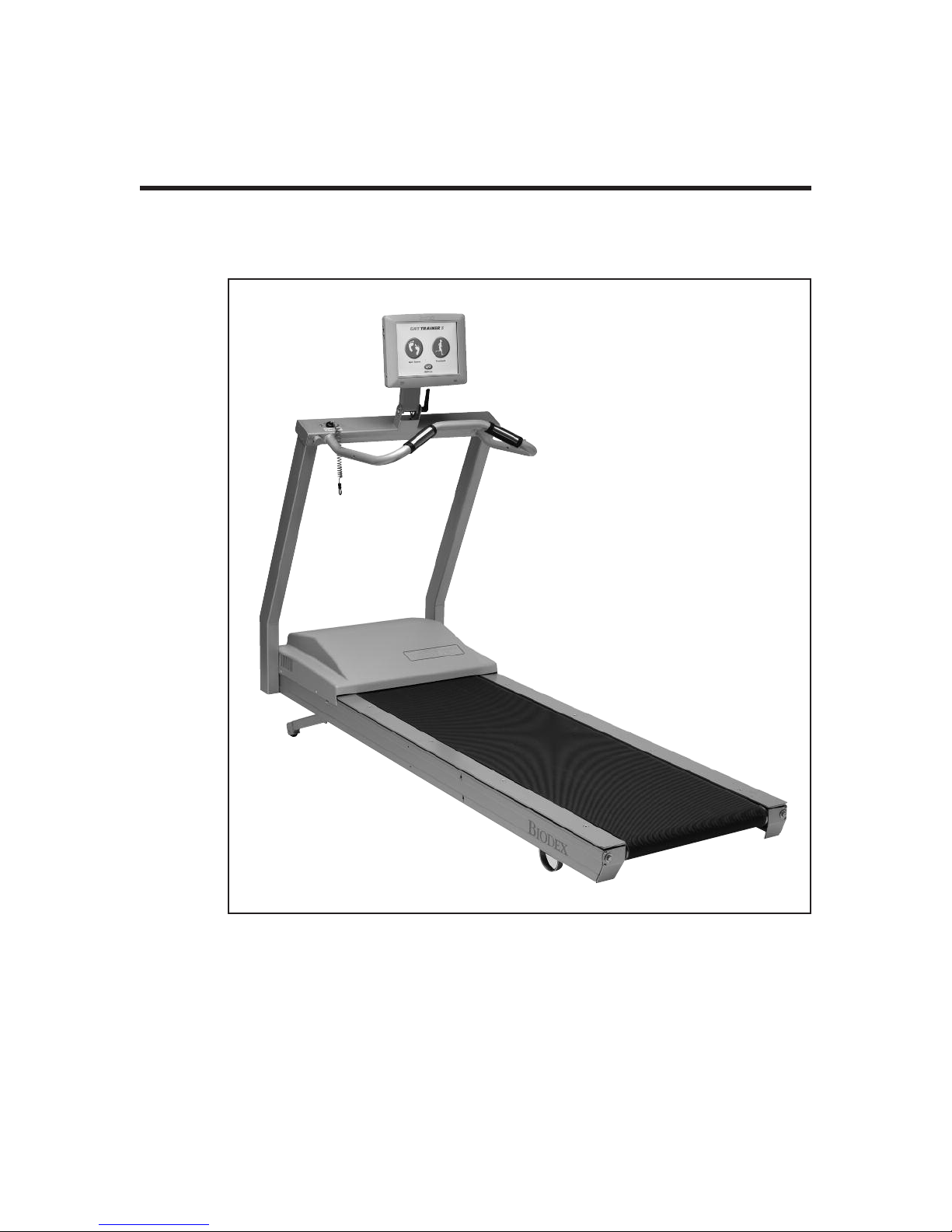
esigned specifically for rehabilitation and retraining of gait for patients with neurologic and
orthopedic gait dysfunctions, the Biodex Gait Trainer provides both the audio and visual feedback
needed to progress patients quickly and safely to normal ambulation.
The Gait Trainer is easy to use. The clinician need only select the patient’s age and height for the
treadmill to automatically calculate the exact speed needed to achieve desired step cycle. The
rhythmic movement and the audio feedback provide patients with added stimulus for retraining
of neural pathways to improve gait pattern.
The Gait Trainer promotes correct stride length for early phase patients. By starting out slowly
(with the zero starting speed and small .1 step cycle speed increments) it is possible to manually
position the patient’s lower extremities in the desired patterns for gait, thus reinforcing the prop-
er techniques early in the rehabilitation process. As the patient progresses, correct stride length is
coupled to the correct step cycle. When belt speed is increased, the patient must either take longer
strides or more strides to stay on target. Normative data allows clinicians to compare patient
progress to baseline norms.
Of course, the Gait Trainer can also be used for many other rehabilitation treadmill applications.
In treadmill mode, its unparalleled speed control, durability, incline and decline in both forward
and reverse directions, digital feedback, low profile, and choice of handrail configurations make
it the ideal choice for virtually any patient young or old.
The Biodex Gait Trainer comes with a printer which is easy to install and resides on the printer
stand.
1. INTRODUCTION
— 1-1 — INTRODUCTION

!
The following safety considerations should be observed for all patients who exercise on the
Biodex Gait Trainer. Additional clinical considerations, specific to gait training, are provided in the
chapter titled: Clinical Applications and References.
1. All patients should consult a physician before beginning any rehabilitation program.
2. Instruct patient on proper use and all Gait Trainer safety features before beginning exercise.
3. Always attach the Safety Lanyard to the patient’s clothing or wrist before allowing exercise to begin.
4. Ensure patient has stretched and warmed-up prior to starting exercise.
5. Do not allow any patient to exercise unattended on the Gait Trainer. Never leave the Gait Trainer run-
ning unattended.
6. Periodically monitor the heart rate of patients exercising on the Gait Trainer.
7. Begin all exercise at a slow pace, increasing speed gradually to patient tolerance and progressing toward
exercise goals. Always inform the patient immediately prior to increasing or decreasing speed or eleva-
tion.
8. If reversing belt direction, bring the Gait Trainer to a complete stop and inform patient that the belt will
begin moving in the opposite direction.
9. Immediately discontinue exercise if patient feels faint, dizzy or short of breath.
10. Never allow anyone to step onto the Gait Trainer while the treadbelt is in motion. Always stop the Gait
Trainer prior to allowing the patient to step up onto the treadbelt.
11. Instruct patients to use the handrails when first learning to walk on the Gait Trainer.
On devrait observer les considérations suivantes de sûreté pour tous les patients qui s'exercent sur
le Gait Trainer 3.
1. Tous les patients doivent voir leur médecin responsable avant d’entreprendre la séance de rééducation.
2. Expliquer au patient la bonne utilisation des systémes de sécurité du tapis avant de démarrer la séance.
3. Connector toujours la sangle de sécurité aux vêtements du patient ou poignet avant que le patient ne
commence à travailler.
4. Vérifier que la patient s’est échauffé et a fait des étirements avant de commencer l’entraînement sur le
tapis.
5. Ne pas laisser le patient seul sur le tapis pendant la séance. Ne jamais laisser le tapis tourner sans
patient et sans surveillance.
6. Surveiller de temps à autre la fréquence cardiaque du patient pendant la séance.
7. Démarrer les protocloes à une vitesse lente et augmenter progressivement la vitesse en fonction de la
tolérance du patient et progres uers les objectifs de la séance. Signaler avant de l’appliquer tonte aug-
mentation ou diminution de vitesse ou d’inclinaison.
8. Avant de changer la direction de déplacement du tapis, arrêter le tapis complétement et expliquer au
patient que le tapis va démarrer dans le sens opposé.
9. Arrêter la séance immédiatement en cas de dyspnée, d’étourdissements ou d’autres signes de malaise.
10. Ne jamais faire monter personne sur le tapis pendant que le tapis est en marche. Arrêter toujours le
tapis avant que le patient ne s’y positionne.
11. Donner la consigne au patient d’utiliser les barres horizontales lors de sa premiére séance sur le tapis.
2. SAFETY CONSIDERATIONS FOR GENERAL USE
— 2-1 — CLINICAL CONSIDERATIONS FOR GENERAL USE

<:=.A6/92"?6;A2?@
PCL printers specifically
HP H470
HP 6000
HP6940
HP6940dt
HP6988
HP9800
HPK5400
HP 5360
HP5650
HP5550
!"&"! & (%
.;B3.0AB?2? <129 2C602&F=2
Logitech M500 Mouse
Seal Shield SSMSV5 Mouse
Targus AMU59US Mouse
Razer Naga RZ01-0028 Mouse
Microsoft 1049 Mouse
Belkin F5L017-USB-BLK Mouse
Toshiba PA3571U-1ETB Mouse
Microsoft 1422 Mouse
Targus AMU75US Mouse
Microsoft 1056, 1051 Mouse
Logitech V220 Mouse
HP WX414AA Mouse
ynex X-PWLMSE Mouse
Toshiba PA3651U-1ETC Mouse
Logitech G500 910-001259 Mouse
BTC M859C Mouse
Logitech M-BJ79 Mouse
ell MOA8BO Mouse
ell M-UK EL3 Mouse
Manhattan 176569 Mouse
!"&+!$%
.;B3.0AB?2? <129 2C602&F=2
Mini Keyboard ACK-5010U USB Keyboard
Adesso AKB-210 Keyboard
Adesso WKB-4000US Keyboard
Adesso ACK-540UB Keyboard
Adesso AKB-110B Keyboard
* Printers and other devices are subject to market availability.
Please check with Biodex customer service if questions arise.
2. CLINICAL CONSIDERATIONS FOR GENERAL USE
CLINICAL CONSIDERATIONS FOR GENERAL USE — 2-2 —

2. CLINICAL CONSIDERATIONS FOR GENERAL USE
— 2-3 — CLINICAL CONSIDERATIONS FOR GENERAL USE
Figure 2.1.
1. Reset Button
2. Remote CRT Monitor Connector
3. PS 2 Connector
4. Ethernet activity lights. Green indicates connectivity. Yellow indicates activity.
5. Auxiliary Com Port (Serial Port)
6. Ethernet Connector (R 45)
7. PCB activity lights. Green indicates compact flash activity. Yellow indicates power on.
8. USB Connectors (suggested to use one of these for printers)
Figure 2.2. Connect the power cable and USB cable to the rear of the printer.
The printer power cable should only be plugged into the dedicated AC receptacle located at the
front of the base. A special IEC adapter cable is provided.
The printer USB should be plugged into one of the USB ports on the side or bottom of the display.
12345
6
7
8

Figure 3.1. Attaching the Safety Lanyard, printer cable and printer.
Included with the Gait Trainer are a printer, printer stand and Safety Lanyard. These should all be
attached/installed prior to operation of the Gait Trainer.
! & &"$ &$)6?21
(See Section 13 for wireless printing information)
(See Figure 3.1.)
The printer cable should be connected to the printer receptacle at the back of the display with the
USB cable end. Attach the opposite end of the cable to the back of the printer. The cord should run
down the back of the display and over the motor cover so as not to be in contact with the moving
belt. Place the printer on the printer stand. Ensure that the printer stand is positioned next to the Gait
Trainer but far enough away so as not to come in contact with the Gait Trainer’s moving parts.
The printer receptacle is for the printer only. Do not plug anything else in this receptacle.
La prose pour imprimante est destinée à la seule imprimante. Ne brancher rien d’autre dans cette prise.
! & &%&+ +$
(See Figure 3.1.)
A Safety Lanyard is provided. The Gait Trainer will not operate unless the lanyard is attached.
Attach the Safety Lanyard at the left corner of the top cross bar supporting the isplay panel. The
round end of the Safety Lanyard attaches to the unit via a Velcro®brand hook and loop fastener.
The clip end of the lanyard should be attached to the patient’s clothing or wrist in a way that does
not interfere with the patient’s exercise.
Disconnecting the Safety Lanyard (left side of Display/Control Panel) or pressing the red Safety
Stop (atop the right side of the Support Bar) at any time will cause the treadbelt to immediately ramp down
to a full stop and reset to 0.0 mph. The Display will read <Safety Lanyard Removed> and the treadbelt will
not restart until the Safety Lanyard is once again in position and/or <Start> is pressed following use of the
Safety Stop. Display data is not lost in either case. Data accumulation will resume once the lanyard is recon-
nected and <Start> has been pressed.
3. SET-UP
— 3-1 — SET-UP
Attach Printer Cable
(underneath display)
Attach Safety Lanyard

$ %&&! !"&!
(See Figures 3.2 – 3.4.)
Figure 3.2.
Figure 3.3.
Figure 3.4. The Biodex Gait Trainer comes with a sturdy support bar installed (Figure 3.2).
Optional Standard (Figure 3.3) and Geriatric/Pediatric handrails (Figure 3.4) are also available.
CONTENTS
SET-UP — 3-2 —

The Biodex Gait Trainer 3 comes with a sturdy support bar, but optional Standard Rehab and
Geriatric/Pediatric handrails are also available. Both optional handrails are installed as follows:
Do not fully tighten any screws until all the screws and hardware have been positioned and
partially secured.
1. Using a Phillips screwdriver, remove the two screws that attach the cover plate to side of the
display support bar. Set the screws and mounting plates aside.
2. Using a 9/16-inch box wrench, attach the optional handrail to the display support bar with a
3/8-inch lock washer and hex head bolt.
3. Slide the handrail mounting bar into the bottom of the optional handrail so that the screw
holes align.
4. Attach the bottom of the handrail to the platform deck frame using two 1/4 - 20 x 1.75-inch
socket-head screws.
5. Using one 1/4 - 20 x 1.75-inch button-head screw, secure the optional handrail to the support
bar. Pass the screw, threads to the outside of the deck, through the support bar first and into
the optional handrail.
6. Tighten all screws.
7. Using a Phillips screwdriver, replace the cover plate on the display support bar with the two
screws set aside in step #1.
8. Repeat the procedure to attach the opposite optional handrail.
: Assembly drawings for the procedure, if needed, are provided on pg. 17-2.
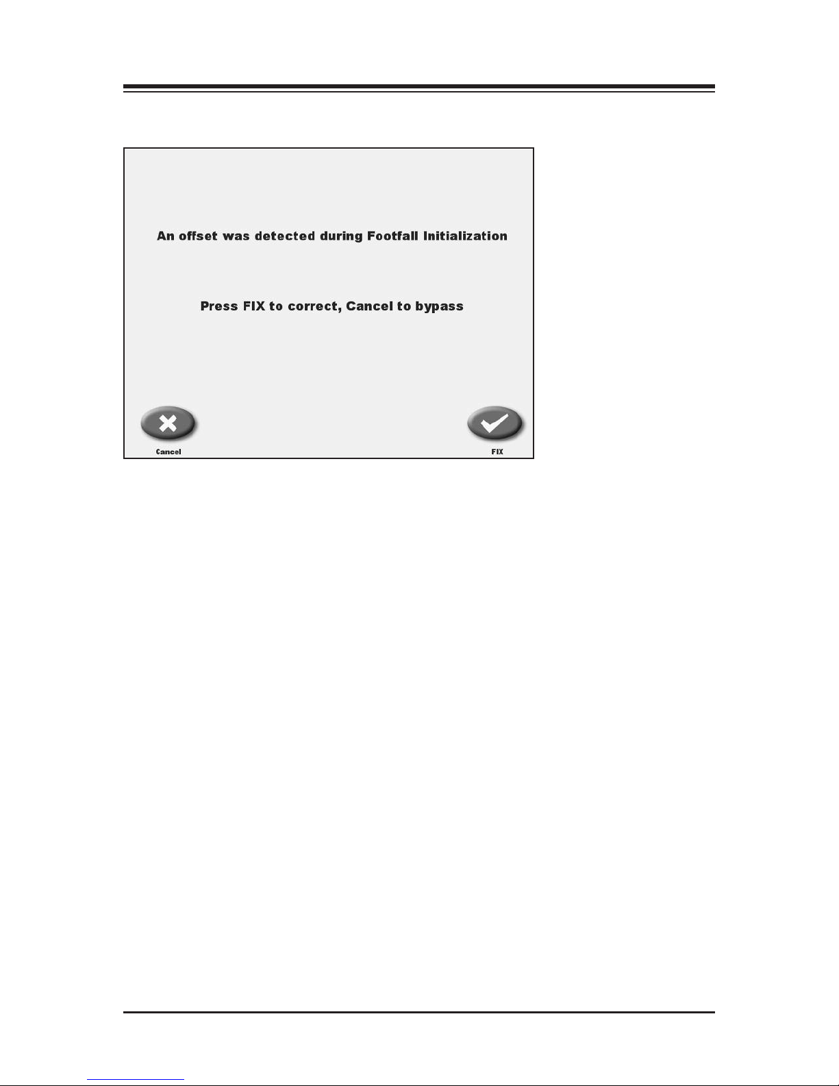
&&$ $( %&$'&! %
The Gait Trainer deck is instrumented with a strain gage at each of the four corners. It is impor-
tant that the Gait Trainer be level for optimal footfall detection. You may see messages concerning
Leveling or Offset Calibration. epending on the situation, instructional screens will lead through
any required process. It is very simple.
%6AB.A6<;
When first installed or should the Gait Trainer be moved, it may be required that the leveling foot
be adjusted. This will require a ¾” wrench.
In this situation, adjust the rear leveling foot by turning it with the wrench in the direction that
will get all four boxes, these represent the (4) strain gages, to turn green.
There is a jam nut that should be loosened first, then re-tighten. Press Ok.
CONTENTS
— 3-3 — SET-UP
%6AB.A6<;
It is not required that the main power switch be turned on and off each day. The Gait Trainer
display will actually go into a sleep mode when not in use. This is the “Screen Saver” function.
This “Not in use time period” can be adjusted in the Configuration menu found in Utilities.
In the event the main powered is cycled on and off, the Gait Trainer will automatically check the
strain gages. If they are out of range, the Gait Trainer will prompt the user with appropriate cor-
rective actions. Again, the process is simple. Just follow the screens. Please do not stand on the
Gait Trainer when making any adjustments to the strain gages or during initialization.
CONTENTS
SET-UP — 3-4 —

If in the unlikely event, the Gait Trainer can not bring the strain gages into the necessary ranges,
the Treadmill function is unaffected and use in the treadmill mode can continue. Please contact
Biodex Customer service to resolve the Gait Trainer problem.
CONTENTS
— 3-5 — SET-UP

The Biodex Gait Trainer can be used for gait training applications, or as a rehabilitation treadmill.
The following section describes use in the Gait Training Mode. Rehabilitation treadmill operation
is described later in this manual.
&&&$ !
The Gait Training Mode is useful for the rehabilitation and retraining of gait for patients with neu-
ralgic and orthopedic gait dysfunctions. It provides both audio and visual feedback for patient
compliance. The rhythmic movement of the treadbelt along with the audio and visual biofeed-
back, provides the necessary stimulus for retraining neural pathways, thus improving the gait pat-
tern of the patient.
It is recommended that the Biodex Unweighing System be used in conjunction with the Gait Trainer
to provide a safe environment for the patient and clinician, and also to allow for proper patient positioning
for weight distribution and coordination of balance.
"!)$'"
(See Figure 4.1)
To provide power to the Gait Trainer, ensure the power plug is connected to an appropriate sock-
et. Press the ON/OFF switch, located on the base of the Gait Trainer in the left corner at the front
end, to the “l” (ON) position.
Figure 4.1. The Gait Trainer Opening Menu.
4. GAIT TRAINING MODE
— 4-1 — GAIT TRAINING MODE

&&&$ $'%$%&'" !$&! %$
(See Figure 4.2)
Figure 4.2. The Gait Trainer User Setup Information screen.
The Opening Menu displays three icons: Gait Trainer, Treadmill and Utilities. Touch <Gait
Trainer> to advance to the User Setup Information screen. This screen allows entry of patient
information and parameters used for gait training.
At the User Setup Information screen, simply touch the appropriate icon to begin entering informa-
tion. A pop-up keypad is used to enter some parameters such as Name and Age. Once the desired
information is entered/selected, touch <Next> to advance to the Footfalls/Historgram screen or
touch <A/V> to advance to the Biofeedback Options Screen. A brief explanation of each parameter
and function on the Gait Training User Setup Information Screen follows.
For all screens, <Next> advances to the next screen, <Back> returns the user to the previous screen.
.6A&?.6;6;4'@2?%2AB=;3<?:.A6<;%0?22;".?.:2A2?@
The first three parameters, Gender, Height and Age, are mandatory fields and must be completed
before gait training can begin.
• Gender: Touch the appropriate icon to choose <Male> or <Female>.
• Height: This setting is used to determine leg length. Touch the appropriate <Height> icon
to select the desired range.
• Age: Range is from 10 to 80 years old. Touch the <Age> keypad and then use the pop-up
keypad to change the value. Touch <OK> to continue.
• Gait Training Time: efault value is 6:00 minutes. Use the ▲or ▼arrows to change the value.
CONTENTS
GAIT TRAINING MODE — 4-2 —

• Name: Optional, touch the pop-up <Keypad> to enter the name. Touch <OK> to continue.
• A/V Biofeedback Options: Touch <A/V Biofeedback> to enter biofeedback options from
the Audio/Visual Biofeedback Options screen.
• <Back>: Go back one screen.
• <Next>: Advance to the next screen.
&52'!(%'!%$
(See Figure 4.3.)
Figure 4.3. The Audio/Visual Biofeedback screen.
The Audio/Visual Biofeedback screen (A/V) is accessed from the Gait Training User Information
screen by touching the <A/V> icon. At this screen, biofeedback parameters can be entered or set.
A brief explanation of each parameter and function follows.
B16<([email protected]6<3221/.08%0?22;".?.:2A2?@.;1B;0A6<;@
• Set Step Length Tolerance Range: Touch <Set Range> and then use the pop-up keypad to increase
or decrease the distance between line.
• Set Visual Biofeedback ON/OFF Interval Time: Touch <ON>, <OFF> or <Interval> and enter the
desired feedback time via the pop-up keyboard.
• Set Audio Biofeedback ON/OFF Interval Time: Touch <ON>, <OFF> or <Interval> and enter the
desired feedback time via the pop-up keyboard. The audio tone is not a metronome tempo. The
audio tone is timed to be in sync with when the target box is to appear. Tone is also based on
your last footfall. You can get a tone without a footfall. After a while due to the rhythmic nature
of walking, the tone falls into a seemingly real-time tempo.
Once you have set/entered the desired parameters on the A/V screen, touch <Next> to return to
the Patient Setup Information Screen.
CONTENTS
— 4-3 — GAIT TRAINING MODE
&!!&%%&!$%$
(See Figure 4.4 – 4.5.)
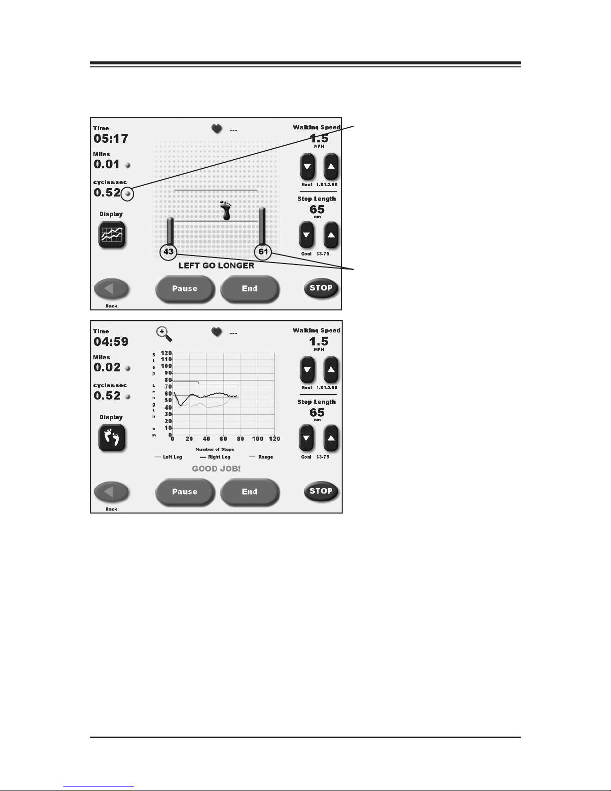
Figures 4.4. and 4.5. Patients can view the Footfalls/Histogram screen with either Footfalls or Histograms
displayed. In the Footfalls screen, the solid foot marks the user's last foot placement while the line is a target
for the next foot placement.
<<A3.99@6@A<4?.:%0?22;".?.:2A2?@
Touch <Next> at the Patient Setup Information screen to advance to the Footfalls/Histogram
screen. At this screen, users can view patient progress via either a footfall or histogram display.
Just touch the appropriate icon at the bottom of the left to toggle between display formats. With
either display, the following parameters can be adjusted at any time as follows:
CONTENTS
GAIT TRAINING MODE — 4-4 —
Toggle by pressing
yellow dot to
display speed as
cycles/sec, MPH,
or meters/sec
Real time (average of last 5
steps) display of step length
Y axis – Step Length can be
scales 0-60 cm, 0-80 cm, 0-100
cm or 0-120 cm.
X axis – can be TIME,
ISTANCE or STEPS
To change the axis label: Before
the gait training has started
simple touch the axis label to
toggle between choices.

• Speed (mph): Located at the top right of the screen. Use the associated ▲and ▼ icons to set this
goal to match the desired cycles per second.
Walking speed is displayed in MPH or KMH. The default value will be according to how the
Gait Trainer is set up (English or Metric). Most people can relate better to MPH or KMH, than
cycles per second. If you want to know what the cycles/second are, toggle the speed on the left.
When step length is increased or decreased, the green lines will move up or down. The patient’s
goal is to place their foot between the lines. The numeric bars show the real time average of the
last 5 step lengths for the respective side. Green bars are good as the patient is stepping within
the lines, Blue will show when the footfall is too short.
Clinical tip – increase the step length to challenge the patient to take longer steps.
For visual and audio biofeedback, the treadbelt speed must be greater than 0.3 mph (0.48 kmh).
The cycle/sec speed and/or step length regulate the treadbelt speed. If treadbelt speed is below 0.3 mph
(.48 kmh) a message will display noting that the treadbelt is moving too slowly for biofeedback.
• Step Length: Located at the bottom right of the screen. Use the associated ▲ and ▼ icons on the
right side of the screen to increase or decrease goal value.
• Distance: Located at the top left of the screen, touch <o> to toggle units of measure between
miles, meters and kilometers.
• Speed (Treadbelt Speed): Located at the top left of the screen, touch the solid yellow dot <o>, to
toggle units of measure between KMH, MPH and meters/second.
• Heart Rate: Heart rate monitoring is accomplished by having the subject hold onto both heart
rate handgrips on the front handrail. The heart rate value will be displayed at the top left of the
screen when the handgrips are held.
• Histogram or Footfall: Located at the bottom left of the screen, touch the desired icon to toggle
between these two choices.
Footfalls: When the patient’s actual footfalls are detected they are displayed with respect to the
line. When the patient falls within the set step length tolerence as set in biofeedback option, the
footfalls are synchronized with the target and are told “good job” by the display. Should they
fall outside of the step length tolerence, the display will tell the patient which footfall is outside
of the range by prompting them to go longer or shorter on the respected foot.
Because footfalls are projected based on the subject's last step the screen is always one step
behind. This should not be apparent once the subject falls into a rythmic walking pattern. If a step does
not go in front of the opposite step, the target box will not appear.
Histogram: isplays footfalls as a 2-pixel wide dot. The X-axis shows distance traveled in
meters and the Y-axis shows the deviation, where 1 pixel is equal to 1cm of deviation. If the
patient goes beyond the S , the histogram will deviate from straight path.
On the histogram graph, the upper and lower lines are the target step lengths plus/minus the
step length tolerence. You will notice that the upper line and lower line are equal to the range of the aver-
age step length.
CONTENTS
— 4-5 — GAIT TRAINING MODE
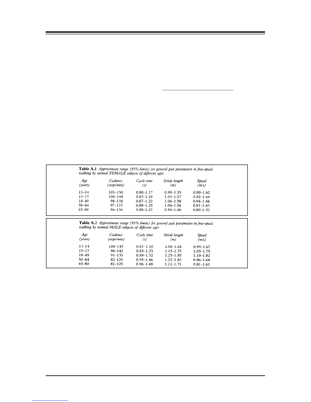
(Refer to Tables A1 and A2.)
The normative data charts provided in this manual can be used to develop rehabilitation pro-
grams and discharge criteria for your patients. The normative values are based on age and gen-
der so comparisons can be easily made.
Clarification of Normative Data for the Gait Trainer: The normative data presented in the Biodex
Gait Trainer 3 id derived from the reference tables in Gait Analysis, An Introduction, 2nd. Edition,
Michael W. Whittle, 1997, pgs. 218-219.
Cycle time in Whittle is seconds, whereas the Gait Trainer uses cycles/second. Therefore, data is presented
as the inverse function of the cycle time:
Cycles per second = Cycles-1
Whittle also presents normative data for stride length. The Gait Trainer uses step length. A stride equals
two steps, therefore, these tables represent stride length divided by two.
5. NORMATIVE DATA
— 5-1 — NORMATIVE DATA

&&$ $&!$+!!"$&!
1. Walking (gait) speed can be increased two ways: Increase step frequency (step cycle) or
increase step length.
2. Step cycle: A successive heel strike for the same foot, i.e. Right step, left step, right step. Set
belt speed based on how many complete successive heel strikes occur within a second. .1 cycle
per second is very slow, 3 cycles per second is fast. Normal walking step cycle approximates
1 cycle per second.
3. Step Target: A theoretical footfall area based on calculated step length. When step target dis-
tance is increased, belt moves faster as steps need to become longer. If target distance is
decreased, belt speed decreases, as steps need to become shorter.
4. Step Length : Is a range [Leg length (cm) x .69] to [Leg length (cm) x .86]. Step Target is placed
within this range plus or minus the entered standard deviation.
5. In Footfall display: Step length tolerence is used to prompt walker if they need to go faster on
either right or left side, or both sides. If footfalls occur within step length tolerence they are
told good job.
6. In Histogram display: Step length tolerence is bandwidth of where step footfalls should occur.
Normal healthy walking at a comfortable pace exhibits step lengths within 3 cm.
&&$ $!"$&!
At this point, you should be ready to begin gait training using the following procedure:
1. Touch the screen to activate the display panel and bring up the Opening Menu touch screen.
Touch <Gait Trainer> to advance to the User Set-Up Information screen.
2. Enter/select the required values on the User Set-Up Information screen. Touch <A/V> to
advance to the Audio/Visual Biofeedback screen.
3. Enter/select the desired values on the Audio/Visual Biofeedback screen. Touch <Next> to
advance to the Footfalls/Histogram screen.
4. Push <Start> to activate the treadbelt. Then increase the speed slowly to a minimum 0.3 mph
for biofeedback.
5. Adjust the <Speed> setting to a comfortable pace for the user. Once the user is comfortable,
touch <Begin Gait Training> to begin the gait training session and record data.
Treadbelt speed must be greater than .3 mph for biofeedback.
6. Instruct the subject to follow the prompts on the screen while attempting to place each foot in
the target area displayed. The system will prompt for each foot (or both feet) to “go longer,”
“go shorter,” or to continue on pace with “good job.”
For histogram display, the yellow line denotes the left leg, the blue line denotes the right leg.
The target range is bracketed by two green horizontal lines across the graph. Touch the magnifying glass
icon to enlarge the histogram viewing area at any time.
7. To pause the gait training session at any time, press <Pause>. The treadbelt speed will decel-
erate slowly until stopping. To resume, touch <Resume> and then press the <▲> Speed icon
to bring the speed back up to the desired level. Touch <Resume Gait Training> to begin gath-
ering data again.
8. When the gait training session is finished, touch <End>. The treadbelt will slow gradually
until it stops.
9. Touch <Results> to display exercise results or touch <Re-Start> to repeat the training session
(all data will be lost).
6. GAIT TRAINER OPERATION
— 6-1 — GAIT TRAINER OPERATION

(See Figures 7.1, 7.2 and 7.3.)
Exercise results can be reviewed from the Exercise Results screen only after touching <End> to
end the exercise session and then touching <Results>.
Figure 7.1. The Exercise Results screen. Note the Exercise Results functions available at the bottom of the
screen.
*$%$%'&%"$&$%
Time: This displays the total elapsed time from the start of the exercise until either the end of the
exercise bout or when the <STOP> button is pushed.
Steps: Total Steps during the exercise time.
Average Speed: Average speed of the belt during exercise session.
Distance: This is the total distance traveled by the belt, which is in essence the distance traveled by
the patient.
Average Walking Speed: Normative values have been established and are dependent on age and sex.
The norms are expressed next to the real time value.
Average Step Cycle: This is calculated by taking an average for the step cycles during the exercise
bout.
Average Step Length: This number is calculated by taking an average for all of the step lengths .
Coefficient of Variance: This is calculated as the amount of variation occurring between footfalls.
7. EXERCISE RESULTS
— 7-1 — EXERCISE RESULTS
Other manuals for 950-400
1
This manual suits for next models
17
Table of contents
Other biodex Treadmill manuals


