OPERATION PROCEDURE ORDER
1) Make sure the total rated current of the Solar Panel Array and Load are less than the rated current
of your Solar Charge Controller –in this case your maximum current is 20A
2) Make sure the polarity of the wiring from your Solar Panel Array, Battery and Load are correctly
matched to prevent the risk of a short circuit which may damage unprotected devices
3) Mount you Solar Charge Controller to your selected surface and fasten it securely using screws
4) Check whether the Battery voltage and Solar Panel Array voltage is within the requested range
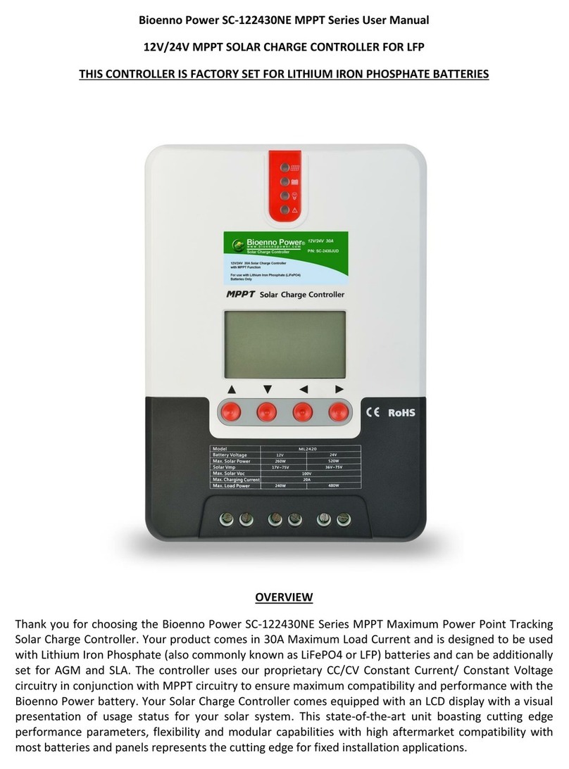
5) Loosen the screw terminals on your Solar Charge Controller –there are 6 screw terminals total
from left to right in this order: Solar Panel Positive, Solar Panel Negative, Battery Positive, Battery
Negative, Load Positive and Load Negative
6) Connect the Battery’s input to your Solar Controller using the two screw terminals in the middle
marked with the Battery pictogram, you may need an adapter –attach the wiring securely but do
not over-torque your Solar Charge Controller’s terminals
7) Connect your Load to your Battery’s output using the Battery as the buffer between the Solar
Panel Array and the Load (we DO NOT recommend using the Load Terminals for most uses) –
attach the wiring securely but do not over-torque your Solar Charge Controller’s terminals
8) Connect the Solar Panel Array to the Solar Panel Input on your Solar Charge Controller using the
two screw terminals on the left marked with the Solar Panel pictogram –attach the wiring
securely but do not over-torque your Solar Charge Controller’s terminals
9) Your Solar Charge Controller should assume standard operation herein
To charge AGM batteries, you have to setup an override in the controller as follows:
The solar controller has an override feature to charge LiFePO4, SLA and AGM batteries. Attach the
battery first to the controller, then see below:
1) The 1st screen is the battery voltage also known as the "home" screen.
2) Push the left red button. The second screen is the float voltage of the solar panel to the battery
(13.8VDC).
3) The 3rd screen is the charge voltage of the battery (14.4VDC).
4) The 4th screen is the regulated voltage to the load (12.6VDC)
5) Screen 5 is the cutoff voltage (10.8VDC)
6) Screen 6 is a timer screen that is not implemented
7) Screen 7 is the battery type. By default "b00" is for Lithium Iron Phosphate batteries. To charge
SLA/AGM batteries, hold the left button for 6 seconds, and the "b00" display will start flashing, then
push the right button to change to "b01".
Screen 2, 3, 4, 5, 6 are hard-coded (hard-programmed) -- there's nothing that you would change on
those screens.

