Biogal PCRun User manual


Table of Contents
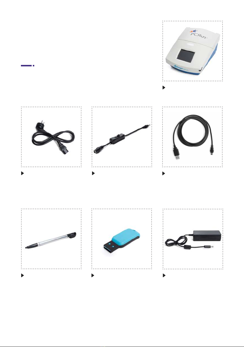
Contents of Box
Starting the PCRun Reader
Assembly of PCRun Reader
®
®
®
Choosing the Default Test Protocol
Running a PCRun Reaction
General Feature
Safety Precautions
User Responsibility
Analysis of Results
Reset PCRun Reader
Aborting a Run
Downloading Files from the PCRun Reader
Deleting Files from the PCRun Reader
Analyzing PCRun Graphs
Instructions for Use of the PCRun Reader Simulator
5
8
6
9
10
7
13
14
15
16
19
Unpacking and Assembling
Operation Guide
Page
®
®
®
®
®

4
5
Unpacking and Assembling
Fig. 4: USB /Micro-USB
connector
Fig. 2: Power cable
Fig. 7: TransformerFig. 5: Stylus
Fig. 1: Reader
Fig. 3: On/off switch
Fig. 6: USB Portable
Memory Stick
(present only in certain
models)
Contents of Box

6
Attention!
Before installing the PCRun Reader please pay attention to the following:
®
®
Do not place the Reader in an area which receives direct light (natural or articial). During
the amplication process light is emitted from the reagents. The generated light is collected,
interpreted and transformed to a readable signal of positivity or negativity. Strong external
light may cause background noise which may be translated into a false positive signal.
Do not place the Reader on the same table with apparatus that my cause vibrations
(centrifuge, vortex, shakers etc). Vibrations will result in unstable readings.
Remove the PCRun Reader (Fig. 8) from the protective packaging and rest on a solid, level
surface allowing approximately 25 cm of clearance space above the unit for opening. Allow
5 cm distance from any wall or object to allow for proper ventilation. Make sure that the
Reader is not housed in area with strong light.
Assembly of PCRun Reader
®
Fig. 8: Front view
Lid
LCD touchscreen
Indicator light
Stylus

7
Fig. 9: Back view
On-off switch
Portable memory
port
Mini USB port Transformer
Outlet
Connect the transformer (Fig. 7) to the power cable (Fig. 2) and then to the back of the PCRun
Reader (Fig. 9). If the Reader comes with an external on/ off switch (Fig. 3) connect it to both the
back of the PCRun Reader and to the transformer cable. The transformer will adapt the voltage
to 220 or 110.
The PCRun Reader is a complete system which contains a heater and luminometer to be used in
conjunction with PCRun reagents designed for the amplication process and analysis of PCRun
molecular reactions. The unit contains a graphical LCD touch panel on which the nal results are
displayed.
• Users are responsible for familiarizing themselves with the product instructions and
limitations.
• External factors such as sample quality and preparation, as well as testing protocols and
laboratory techniques, may inuence the nal results. It is the user’s responsibility to select
the proper sample material which meets the criteria of the chosen test.
• As with any test method utilized for in vitro diagnostics, the results obtained from use of the
PCRun technology should be interpreted together with the results of other tests.
• Operate the instrument on a solid dry surface away from a strong light source.
• Ensure the laboratory electrical supply is appropriate and surge protected.
• The PCRun Reader should be switched off when not in use.
• Do not open the casing of the Reader.
• Maintenance of the unit must be carried out by Biogal personnel only.
General Feature
User Responsibility
Safety Precautions
®
®
®
®
®
®
®

8
Fig. 10 | Model B
Power cord
connection to
transformer
Connection to
Reader
Fig. 10 | Model A
Prior to using the PCRun Reader make sure, that it has been set up according to the
“Unpacking and Assembling” instructions.
1.1
Turn on the PCRun Reader using the on/off switch located on the power cord
(Fig. 10, Model A) or on the back of the Reader (Fig.10, Model B).
Operation Guide
®
®
®
1. Starting the PCRun Reader

9
1.2
The following display will appear briey (Fig 11). The
PCRun Code # and the rmware that is installed in
the Reader are located on the bottom of the screen.
1.3
The main screen (Fig. 12) will replace the Logo
display. The following details will be displayed:
2.1
The default test protocol setting is GENERIC and
is suitable for most of the PCRun reactions.
Alternate protocols may be recommended for
certain kits. Prior to using the Reader, check the kit
instructions to determine which protocol is suitable
for your test. In the case that a different protocol is
recommended, the following instructions will explain
how to change the program temporarily or to dene
a new default program. Using the stylus, activate
the Test: GENERIC tab (Fig. 12). The names of the
various protocols will appear in the window. Choose
the recommended protocol (Fig. 13).
• Warm up ?
• Test: GENERIC
• Settings
• Files
• Present date and hour
• Thermometer with ambient temperature
2. Choosing the Default Test Protocol
Fig. 11
Fig. 12
Fig. 13
®
®

10
3.1
Using the stylus press Warm Up? (Fig. 12). The
message on the screen will change to grey and
the words Warming up will appear. In addition, the
indicator light and the thermometer will change to
orange (Fig. 14).
If you will be using the protocol for a single application press Select located on the bottom right
hand side of the screen. If you choose to make the new protocol the default setting, press Make
default located on the bottom left side of the screen. Follow by pressing Select.
3. Running a PCRun Reaction
3.2
Once the temperature of the Reader has reached
its target (60°C) the message will change to Run test.
The indicator light and the thermometer on the touch
screen will change to green. The temperature noted
above the thermometer will be 60°C (Fig. 15).
Fig. 15
®Fig. 14
3.3
Open the lid of the Reader and load the reaction tubes
into the internal wells. Take note of where the tubes
are placed (Fig. 16).
Fig. 16
11
3.4
Close lid completely. Do not open until completion of
the test.
3.5
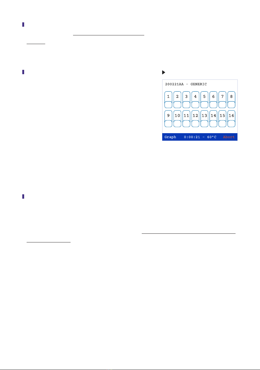
Use the stylus to activate the Run test tab (Fig. 15).
The indicator light will turn red and the screen will
change (Fig 17). The number on the upper left-hand
side of the screen is the “run number”. The number
is composed of the date in reverse accompanied by
two letters. If more than one run is performed on the
same day the number will remain the same and the
letters will change. The test protocol is located in the
top middle section of the screen. The time period
which has passed from initiation of the run can be
seen on the bottom middle section of the screen.
Fig. 17
3.6
Sixteen numbered rectangles are located in the middle section of the screen. Each numbered
rectangle represents a well in which a reaction can be placed. After approximately 5 min all the
numbered rectangles on the touch screen will turn grey, indicating that the amplication process
has begun. Most reactions are completed in 60 min. Do not open the lid of the Reader until the
reaction has ended.

12
3.7
During the amplication process, the screen can
be switched to a histogram plot by pressing Graph
located on the bottom left hand side of the screen
(Fig 18). Using the stylus, press each number on
the tab screen, which represents the sample to be
viewed. The activated tabs will be accented with a
black border. (The graph screen can display only 8
samples at a time). Activate the Graph command.
The graphical display will appear. A row of color
coded numbers can be seen above the graphs
(Fig 19). The numbers and colors correspond to the
activated sample wells. Return to the numbered tab
screen by activating Back (lower right side of the
screen). Positive reactions will be seen on the graph
screen as the reaction progresses at any time point
of the run. If a reaction is positive, the numbered
rectangles on the tab screen will change to red and
the time at which the reaction was at its maximum
(Time to Peak) will be noted under the positive sign.
Different from the positive results, the negative green
results will appear only at the end of the run (Fig 20).
Fig. 18
Fig. 19
3.8
Once the reaction is complete activate Done on the
lower right side of the screen (Fig. 20). The heating
unit of the Reader will turn off automatically if not in
use for 15 minutes.
Fig. 20

13
The results can be viewed in two formats, numerical tab (Fig. 20) or graphical histogram
(Fig. 19). It is highly recommended that the user become familiar with the formats and make a
point of examining both. It is particularly important to differentiate between background noise and
true positive results. Poorly prepared samples containing inhibitors will result in unstable readings
and potential false positives or negatives. The selection of graphs presented in Section 9, page 16
will help in understanding irregular graphs.
The PCRun Reader has a reset button that is
designed to be used when the program does
not respond as expected. It can be found on
the lower right side of the Reader (Fig. 21). To reset
the program, insert the stylus into the small aperture
for 2 seconds. Once the stylus is removed, the
program will appear. If the problem continues please
contact Biogal for assistance.
4. Analysis of Results
5. Reset PCRun Reader Fig. 21
®
®
In cases when a reaction has been initiated and must be ended prior to summation, the run can be
aborted by pressing the Abort command on the lower right side of the tab screen (Fig. 22). Once
the command is activated, a new screen display will appear (Fig. 23). To save the run activate
Save and Abort. To end the run without saving the data activate Abort. If Abort was activated
accidently then press Continue Run.
6. Aborting a Run
Fig. 22 Fig. 23
14
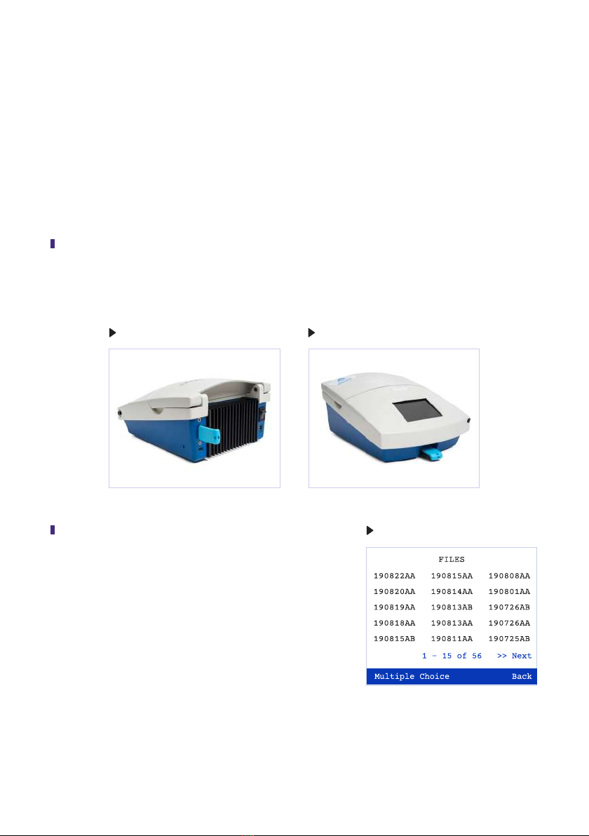
One hundred and fty les can be stored, but only fteen can be displayed on the screen at a time.
The number of runs displayed on the active page and the total number of runs stored in the Reader
can be seen on the bottom middle of the screen. The Files menu contains 10 pages which can be
ipped through by pressing Next (right bottom of the screen, Fig. 26). To return to the previous
pages activate Back. The le codes relate to the date in which the test was performed and are the
date in reverse (160503AB is the 3rd of May 2016). The rst run of the day will receive the sux AA
and the second AB. This coding will continue for each additional run on that specic day.
7. Downloading Files from the PCRrun Reader
7.2
Open the Files menu. A list of the last les will appear
(Fig. 26). To access the older les activate the Next
command. A new screen will open containing tests
run at an earlier date. Continue activating the Next
command until the desired les are located.
7.1
Place the portable memory stick into the USB port. Depending on the model, the port will either
be on the front or back of the Reader (Fig. 24, 25).
Fig. 26
®
Fig. 25Fig. 24
15
7.4
Remove the portable memory stick and turn off the Reader. Place the memory stick into the
USB port of a computer. Find the le according to the date/code. The le will appear in the
format of an Excel sheet which can be analyzed on your personal computer using a Simulator
found on the portable memory stick received with the Reader. Instructions for employing the
Simulator are included with this instruction manual in Section 10, Page 19.
7.3
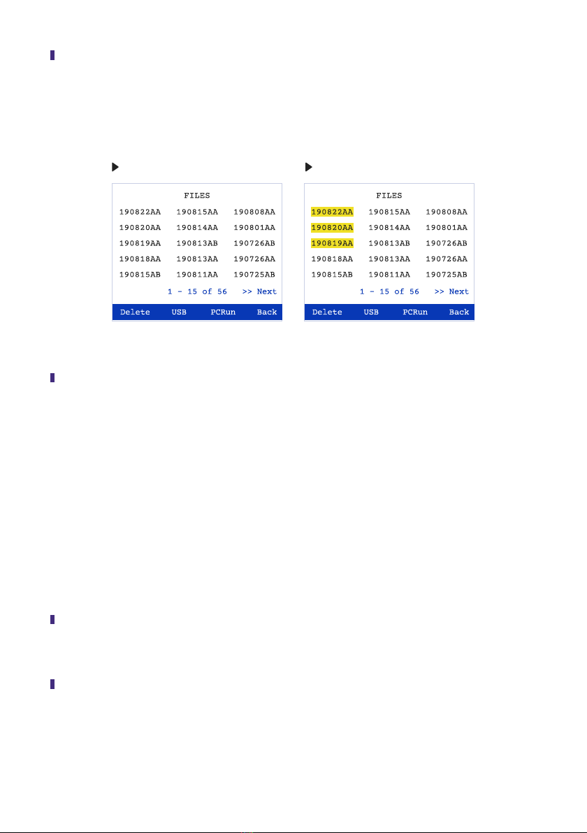
Press the Multiple Choice command (Fig. 26). A new window will appear (Fig. 27). Select the
le or les which you wish to transfer to the portable memory stick. Press the USB command
(bottom of screen, Fig. 28). The message; File copied to memory stick will appear on the
screen.
Fig. 28Fig. 27
8.2
Press the Multiple Choice command and then select the le or les which you wish to delete.
Press the Delete command. The Files menu will appear and the deleted les will be missing
8.1
Open the Files menu (Fig. 15). To access the older les activate the Next command.
Continue activating the Next command until the desired les are located.
The Reader can store one hundred and fty les. When full, the earliest les will be automatically
deleted to make place for the new runs. The les can also be deleted manually using the following
instructions:
8. Deleting Files from the PCRun Reader
®
16
In this section, you will be able to study graphs which may appear on your screen at some stage
of your work with the PCRun Reader. The shape and size of the graph, which appears during
a reaction is affected by the quality of the sample used for the test. In addition, the surrounding
environment can affect the results. Make sure that the Reader has been placed on a solid table
away from any machinery that may cause vibration and in an area where there is no strong or
direct light.
A positive result should have the appearance of
a clear histogram shape, as seen in Fig. 29.
9. Analyzing PCRun Graphs
®
®
Fig. 29
The graph in Fig. 30 may be observed if the
PCRun Reader has been placed on a surface
which receives mild vibrations. At the end of the
run the Reader may even interpret some of the
peaks as positive if they have a Gaussian shape.
The recommendation is to move the Reader to a
more suitable area and repeat the test.
®
Fig. 30
The peaks in Fig. 31 are clear, but to the right of
the curve, low peaks with a at top are present.
This phenomena can occur if the lid of the
Reader is disturbed briey during the run or if
there has been a short change in the electrical
current. In most cases the internal analysis
program can deal with such situations, but if the
secondary peaks are higher than the primary
peaks the machine may return an inaccurate
Time to Peak value and the test should be
repeated if necessary.
Fig. 31

17
The graph in Fig. 32 contains a sharp high red
peak containing a spread left lower arm and
a relatively low at purple curve. Poorly prepared
samples will result in this form of graph which
may be dicult for the PCRun Reader to
analyze. The red peak is obviously positive while
the purple peak may be questionable. If possible
an additional extraction should be performed.
The double peaked graph seen in Fig. 33 may
appear when the reagents have not been allowed
to completely dissolve following the addition
of the sample or when there are large bubbles
within the reaction mix resulting in separation of
the uid into two phases. The PCRun Reader
has been designed to return a Time to Peak of
the later and higher peak.
Fig. 32
Fig. 33
®
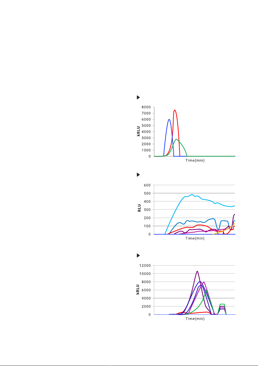
kRLU
®
In incidences that the target gene is found in
very low concentrations or the extracted sample
contains inhibitors the peaks will be very low, in
the RLU (Relative Light Unit) range. The PCRun
Reader will usually be able to interpret the
negative peaks (red) from the true positive peak
(purple) (Fig. 34).
Fig. 34
100
0
200
300
400
500
600
700
800
Time(min)
RLU
®

18
If strong positive tests are run beside a weak
positive test (pink peak) the low peak may be
hidden by the larger peaks. The PCRun Reader
will detect these peaks and return a positive
response on the tab screen (Fig. 35).
®
Fig. 35
Fig. 36
In order to visualize the low peaks deactivate all
of the tabs relating to the strong reactions.
The y axis will change from kRLU to RLU and the
peak will appear as a clear histogram (Fig. 36).
2000
0
4000
6000
8000
10000
12000
Time(min)
kRLU

19
The simulator can be used for analysis of the Excel les produced by the PCRun Reader.
The rst step in the process is to transfer the chosen le to a portable memory stick and copy the
le onto your computer. To Download Files from the PCRun Reader see Section 7, pages 14-
15. You will receive the PCRun Simulator on the portable memory stick which is supplied with
the Reader. Save the simulator le to your computer. The following instructions describe how to
transfer the raw data collected from the PCRun to the Simulator.
10. Instructions for Use of the PCRun Reader Simulator
®
®
®
1. Save the le which you downloaded from the Reader to your personal computer.
2. Open the Excel le which you transferred to your computer.
3. Activate the “Select All Button” on the upper left hand side of the sheet (Fig. 38).
4. The entire worksheet will be selected and shaded light grey.
5. Copy the selected sheet.
6. Open the PCRun Simulator. The le consists of a workbook containing 4 worksheets.
You will see the tabs of the 4 worksheets on the bottom of the open worksheet.
7. Activate the “Paste entire.cvs le here” tab. Once open, locate the top of the worksheet (A1).
Place the cursor on the A1 cell and paste the raw data onto the sheet.
8. If performed properly you will see the graphical and numerical results of your le on the
“Results and Parameters-60” worksheet.
9. This is a standard Excel workbook and modications can be made using excel commands.
10. Save the le after completing any changes made.
Select All Button
Fig. 38
®
®
®

20
For assistance please contact Biogal Galed Labs by
Table of contents
Other Biogal Measuring Instrument manuals

Popular Measuring Instrument manuals by other brands

NorthStar
NorthStar EXPLORER W310 Installation and operation manual

Extech Instruments
Extech Instruments MO53 user manual

Elvaco
Elvaco CMe2100 Quick manual

Seikom Electronic
Seikom Electronic NLSW2aS3 manual

Pyramid Technical Consultants
Pyramid Technical Consultants F3200E user manual

Tektronix
Tektronix VM700T user manual


Sperry instrument
Sperry instrument DSA-540A operating instructions

CPS
CPS HVP-252 instruction manual

Kamstrup
Kamstrup MULTICAL 61 Installation and user guide

Emerson
Emerson Penberthy Installation, operation and maintenance instructions

Starrett
Starrett W798 user manual

Honeywell
Honeywell SM-RI-X instruction manual