Biological Controls MICROCON EXC7 User manual
8/19/2010
MICROCON®
EXC7 and EXC7-UV
User Manual
Read and Save these Instructions
Manufactured by
749 Hope Road, Suite A- Eatontown, NJ 07724 USA
Tel: 800-224-9768, 732-389-8922 Fax: 732-389-8821
www.biologicalcontrols.com

Copyright 2010 Biological Controls 8/19/2010

Copyright 2010 Biological Controls 8/19/2010
SAFETY INSTRUCTIONS
Understand the signal words that are
universally used for overall safety.
•DANGER
•WARNING
•CAUTION
DANGER identifies the most serious
hazards, which will result in severe
personal injury or death.
WARNING signifies hazards, which
could result in personal injury or death.
CAUTION is used to identify unsafe
practices, which would result in minor
personal injury or product and property
damage.
BEFORE
INSTALLATION OR PERFORMING
MAINTENANCE OR SERVICE, TURN
OFF THE MAIN HIGH VOLTAGE
POWER BREAKER TO THE UNIT.
ELECTRICAL SHOCK CAN CAUSE
INJURY OR DEATH. THERE MAY BE
MORE THAN ONE DISCONNECT.
READ INSTRUCTION
MANUAL THOROUGHLY AND
FOLLOW ANY WARNINGS OR
CAUTIONS IN THIS MANUAL AND
ATTACHED TO THE UNIT BEFORE
STARTING INSTALLATION OR
MAINTENANCE ACTIVITIES.
IMPROPER INSTALLATION,
ADJUSTMENT, ALTERATION,
SERVICE, MAINTENANCE, OR USE
CAN CAUSE FIRE, ELECTRICAL
SHOCK, OR OTHER CONDITIONS
THAT MAY CAUSE PERSONAL
INJURY OR PROPERTY DAMAGE.
WEAR SAFETY GLASSES AND WORK
GLOVES AND FOLLOW ALL SAFETY
LOCAL BUILDING AND ELECTRICAL
CODES. CONSULT A QUALIFIED
INSTALLER, SERVICE AGENCY OR
YOUR SUPPLIER FOR INFORMATION
OR ASSISTANCE.
NEVER OPERATE THE
UNIT WITH THE BLOWER EXHAUST
PORT UNCOVERED TO PREVENT
CONTACT WITH THE BLOWER
IMPELLER BLADES. ALWAYS WAIT
UNIT THE BLOWER STOPS SPINNING
BEFORE UNCOVERING THE
IMPELLER.
NEVER EXPOSE EYES
OR SKIN TO ULTRAVIOLET LIGHT
FROM ANY SOURCE. UV LAMPS
MUST BE OFF BEFORE OPENING THE
EXC-UV CHASSIS TO PERFORM
MAINTENANCE OR SERVICE.
PERSONAL INJURY MAY RESULT.
THE UV LAMP
CONTAINS A SMALL QUANTITY OF
MERCURY. IF THE LAMP BREAKS,
CLEAN AND DISPOSE OF WITH CARE.

Copyright 2010 Biological Controls 8/19/2010
Blower Module
Filter
Module Control Panel
Interconnect Cable Assembly
Filter Module

Copyright 2010 Biological Controls 8/19/2010
Table of Contents
Section: Page #
1. INTRODUCTION...........................................................................................................................................................1
2. INSTALLATION MECHANICAL................................................................................................................................2
2.1. System Ducting ................................................................................................................................................................2
2.2. Blower Module-Mechanical............................................................................................................................................2
2.3. Filter Module-Mechanical ..............................................................................................................................................2
2.3.1. Blower Intake collar-plate ..............................................................................................................................................3
2.3.2. Exhaust collar-plate ¼ and ½ HP Blower Modules......................................................................................................3
2.4. Spacing Modules and Components ...............................................................................................................................3
3. INSTALLATION ELECTRICAL..................................................................................................................................3
3.1. Blower Module-Electrical...............................................................................................................................................3
3.1.1. High Voltage Wall Switch (optional) .............................................................................................................................3
3.2. Filter Module-Electrical..................................................................................................................................................3
3.2.1. Blower to Filter Module Interconnect Cable Assembly ...............................................................................................4
3.2.2. Remote Control-Cable (24VDC) ....................................................................................................................................4
3.2.3. 24VDC Remote Controls (optional)...............................................................................................................................4
3.2.4. Switch Plate Control Unit (optional)..............................................................................................................................4
3.2.5. Key-Switch (optional)......................................................................................................................................................5
4. SYSTEM START-UP......................................................................................................................................................5
5. MAINTENANCE INFORMATION..............................................................................................................................6
5.1. Blower Module.................................................................................................................................................................6
5.1.1. Blower Removal...............................................................................................................................................................6
5.2. Filter Module ...................................................................................................................................................................6
5.2.1. Cleaning............................................................................................................................................................................7
5.2.2. Hour Meter ......................................................................................................................................................................7
5.3. Filter Renewal..................................................................................................................................................................7
5.3.1. Pre-Filter..........................................................................................................................................................................7
5.3.2. HEPA Filter .....................................................................................................................................................................7
5.4. UV Lamp Renewal ..........................................................................................................................................................8
6. System Applications ........................................................................................................................................................9
6.1. Creating A Negative Pressure Room..............................................................................................................................9
6.2. Room Filtration Only....................................................................................................................................................10
7. FACTORY RETURNS (RMA) ....................................................................................................................................10
8. WARRANTY.................................................................................................................................................................10
8.1. Making a Warranty Claim ...........................................................................................................................................10
9. SPECIFICATIONS.......................................................................................................................................................12
9.1. Filter Module .................................................................................................................................................................12
9.2. Blower Modules.............................................................................................................................................................12
10. ASSEMBLY FIGURES & DIMENSIONS..................................................................................................................13
10.1. Filter Module .................................................................................................................................................................13
10.2. Blower Module...............................................................................................................................................................14
11. SCHEMATICS..............................................................................................................................................................15
11.1. Typical System 115V Schematic...................................................................................................................................15
11.2. Typical System 230V Schematic...................................................................................................................................15
11.3. Typical System 1/5 HP 2-Speed Motor Schematic.....................................................................................................16
11.4. Remote Wall Switch Option Schematics......................................................................................................................16
12. EXC7 PARTS LIST.......................................................................................................................................................17
Copyright 2010 Biological Controls 1 8/19/2010
MICROCON®
EXC7 and EXC7-UV
1. INTRODUCTION
The MICROCON® EXC7 and EXC7-UV are HEPA-Filter based filtration systems that provide
superior room air-purification. The difference between the EXC7 and the EXC7-UV is the addition
of the UVC germicidal light components located in the Filter Module (FM); otherwise, the filter
modules are identical. The Blower Module (BM) portion of the system contains a 1/5hp, ¼ hp
motor, or ½ hp blower motor. All of the configurations are capable of producing either negative or
positive room-pressure environments.
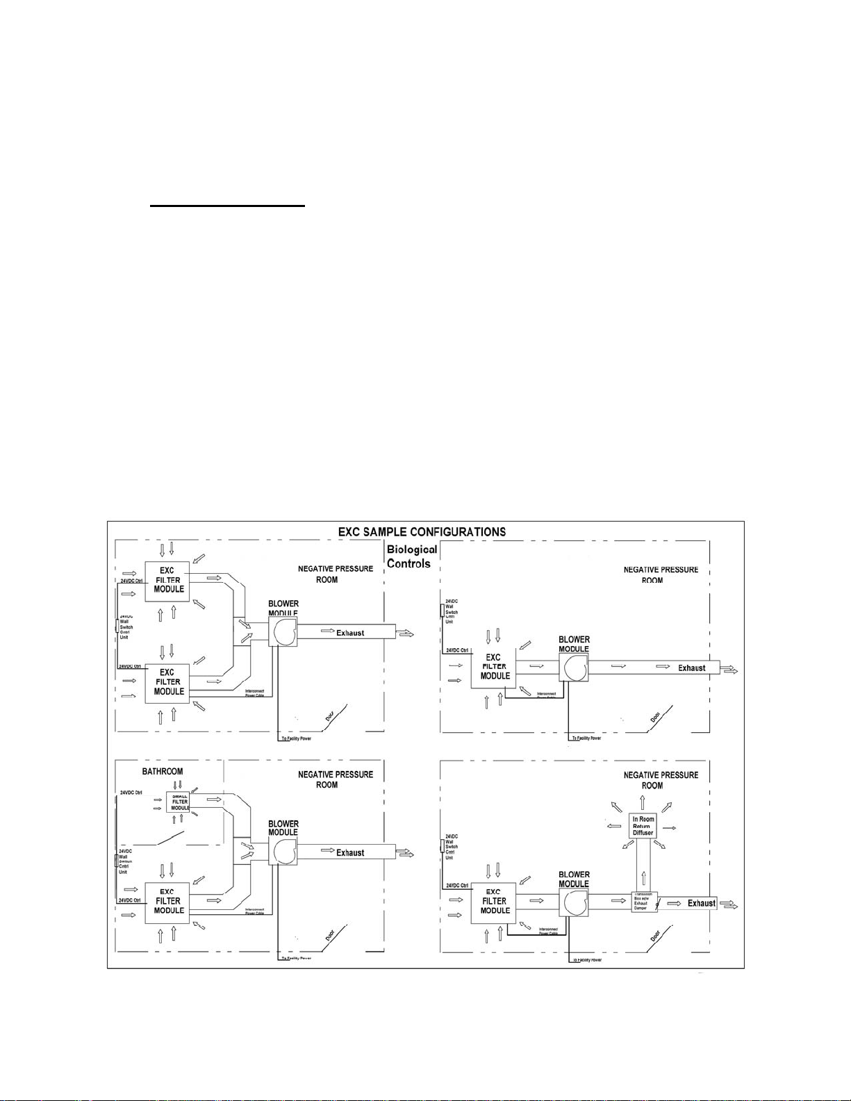
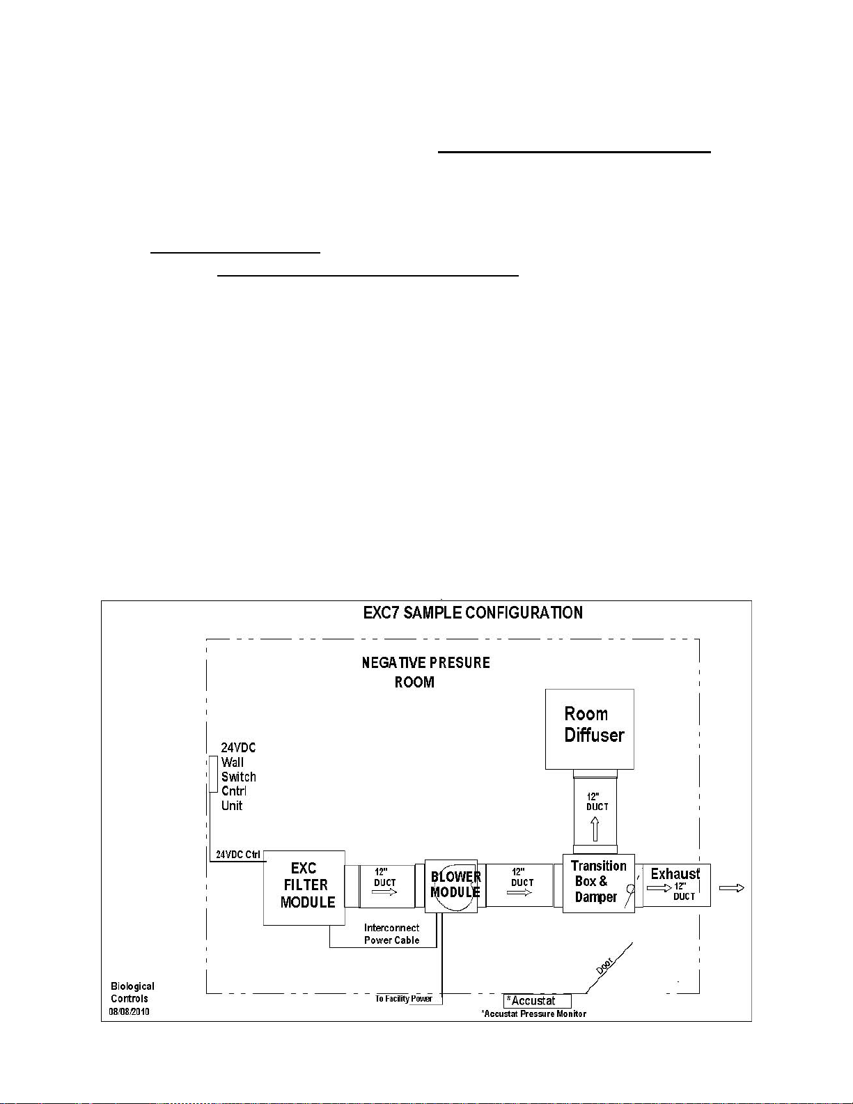
The system is typically equipped with a single Blower Module and one or two Filter Modules. The
components are mounted separately and interconnected with 10” or 12” diameter ducting and with
a provided connectorized Interconnect Cable Assembly.
When a controlled negative room-pressure is required, the system will include a ceiling diffuser
and an exhaust control-duct (transition box with damper). Several low voltage (24V) remote power
control and monitoring options are available.

Copyright 2010 Biological Controls 2 8/19/2010
2. INSTALLATION MECHANICAL
Turn off power at the facility fuse or circuit breaker panel before
proceeding with wiring or installation activities.
The system has more than one electrical-disconnect.
Always Support the Equipment Directly From Building Structure. Obtain an
approved fixture attachment design before proceeding with the installation. The
ceiling support system of the building must be checked to assure that it is
sufficient to carry the weight of the hardware.
2.1. System Ducting
Connect the ducting to the Blower Module, Filter Module(s), room diffusers, and transition boxes
per the system design. Secure the ducting to the inlet and exhaust collars making sure that no air-
leaks exist in the system. Ducts should run in straight lines whenever possible since elbows, bends,
and long runs will decrease the system airflow capacity (cfm).
When maximum CFM is desired, use twelve (12“) ducting wherever possible. Blower and Filter
Modules are typically equipped with 12” duct-collars. The exception is with the smaller 1/5 hp
Blower Module option that use 10” duct-collars. A 10”- 12” adaptor is added to systems that use
the 1/5hp blower module. The same adaptor may be fitted to the Filter Module if it is desired to use
10” ducting between the two components.
Solid-wall ducting is generally preferred over flex-ducting since it provides the lowest air
resistance and best CFM performance. Flex-ducting is used where the speed and ease of installation
is the priority. A combination of duct types and sizes is also an option.
2.2. Blower Module-Mechanical
The Blower Module can be mounted on a platform or suspended. Typically it is mounted above a
suspending ceiling-grid and supported by the four corners of the chassis. The Blower Module is
designed to mount in any position depending upon the height restrictions within the ceiling area.
The unit may be supported using threaded rod, chain or perforated metal straps. All corners and
sides of the larger chassis are equipped with small depression marks in the sheet-metal to mark
standard support locations. Drill out at least four (4) of the chassis depressions to attach the desired
hardware. A set of four (4) eye-bolts eq/w nuts are provided with each Blower Module (1/4 x 20 w/
9/16” ID diameter loop) for a chain support system. The eye-bolts typically extend 15/16 inches off
the mounting surface of the chassis. To prevent air leaks, always calk air-gaps around holes or
mounting hardware attached to the chassis.
The 1/5 hp blower module chassis dimensions are smaller than the ½ and ¼ hp Blower Module
chassis. See the specifications for dimensions. In general, the 1/5 hp system is equipped for 10 inch
ducts and the ¼ and ½ hp systems utilizes 12” ducting. Adaptors may be equipped when required.
2.3. Filter Module-Mechanical
The MICROCON® EXC7 and UV Filter Modules are designed to fit within the standard (nominal
24" x 24") T-bar hardware used to suspend ceiling tiles. Gasket each Filter Module onto the T-'bar
grid surface to provide an air-tight seal between the module and the T-bar channels.
Four (4) small brackets located on the top of the Filter Module chassis must be used to level and support the
weight of the unit using approved cable, wire, or chain hardware.

Copyright 2010 Biological Controls 3 8/19/2010
2.3.1. Blower Intake collar-plate
To avoid freight damage, the duct collar-plate is usually mounted with just four (4) sheet metal
screws with the duct-collar facing into the blower chassis,. The plate must be turned around prior to
installation and reattached using these screws and ten (10) others packaged in a small plastic bag
taped to the Blower Module.
The plate may be attached in one of two (2) positions since the collar is not centered on the blower
chassis. Select the position that best aligns the inlet duct-work with the chassis.
2.3.2. Exhaust collar-plate ¼ and ½ HP Blower Modules
This plate is the same part as the Inlet Collar but has only one correct mounting and is shipped in
the proper position. The collar must align with the blower chassis exhaust port opening.
2.4. Spacing Modules and Components
The distance between a Blower Module and Filter Module cannot exceed nine (9’) feet without a
custom-length Interconnect Cable Assembly. A “slave” Filter Module (a second Filter Module)
requires no Interconnect Cable; therefore, spacing is determined by the duct length restrictions
only.
The distance between the Filter Module intake-grille (door) and any ceiling diffuser should be at
least 6-8 feet to avoid a “short-circuit” of air-circulation. This happens if most of the air-circulation
occurs only between the Filter Module and the ceiling diffuser; as opposed to dispersing the air
more evenly throughout a room.
3. INSTALLATION ELECTRICAL
Turn off power at the facility fuse or circuit breaker panel before proceeding
with wiring or installation activities.
All electrical installation and maintenance must be performed by qualified
individuals and in accordance with the National Electrical Code. ANSI/NFPA
70-1999 and local codes.
3.1. Blower Module-Electrical
The module contains an electrical box to connect to the facility high voltage source (115/230VAC
50/60Hz). The electrical box contains a fuse or breaker to protect the internal wiring. Follow the
appropriate wiring schematic in the appendix depending upon the voltage source available at the
facility power panel. Note that the blower module has been pre-wired for a specific voltage.
Always check the serial number label to confirm the power requirements.
3.1.1. High Voltage Wall Switch (optional)
A high voltage wall switch may be installed to control the input power to the Blower Module.
The switch is provided by the installing electrician.
3.2. Filter Module-Electrical
The Filter Module contains the system power switch, pressure gauge, and optional Hour-Meter. It
also contains some additional components when the remote monitoring and power control options
are provided. Note that the UV lamps for EXCFM-UV units are not installed to protect them
during shipping. The lamps are packaged and taped to the inside of the unit. The lamps should be
installed before adding duct-work to the unit. They can be accessed and installed through the 12”
duct opening in the side of the unit. If not, the bulbs can be accessed by removing the HEPA filter.
Copyright 2010 Biological Controls 4 8/19/2010
Make sure the lamps are clean before installing them into the bi-pin connectors mounted inside the
filter module. The quartz glass may become damaged (etched) when powered with finger grease or
other debris on the lamp surfaces.
3.2.1. Blower to Filter Module Interconnect Cable Assembly
A 10- foot (10’) five (5) conductor wiring-harness is included with each Filter Module. This cable
contains the 120-230VAC circuits necessary to operate the system. It is fitted with insulated
molded-connectors at each end that mate to connectors equipped on the Blower and Filter Module
units. Connect the Filter Module to the Blower Module using the interconnect cable after all
mechanical work is completed.
3.2.2. Remote Control-Cable (24VDC)
When an optional 24VDC remote wall-switch controller is employed an 18-22ga. low voltage cable
is connected between the Filter Module and a wall mounted switch or control unit. Note that the
Filter-Module front panel power-switch will over-ride a remote switch; therefore, the Filter Module
front panel power switch must remain in the "ON" position to activate the remote control function.
The Filter Module power switch will illuminate only when both the Filter Module Power switch
and the remote key-switch are in the "ON" position. Some Filter Modules are equipped with an
internal 24VDC power module. A label near the exit port for the low voltage control cable
indicates the presence of the 24VDC power module.
The internal 24VDC power module is hard-wired to be on 24/7 and there is no
power-off switch. The Blower Module High Voltage must be turned off at the
facility circuit breaker panel or the Interconnect Cable Assembly must be
unplugged from one end to turn off the 24VDC low voltage power.
3.2.3. 24VDC Remote Controls (optional)
Several methods may be used to provide a 24VDC low voltage “on/off” remote-control function
for the system. See the schematic section of this document. Use standard alarm or thermostat-type
wiring to extend the control cable if needed. The control cable is provided on the Filter Module
only when the remote switching option is ordered.
•A standard single-pole light switch (provided by the installing electrician).
•A Key-Switch mounted on a stainless-steel switch-plate (available from Biological
Controls). Part # KSW1 or KSW2 adds a green Power "ON" LED.
•Facility management system capable of providing a “dry-contact” single-pole relay.
•Wall Plate Control Unit (see description below). Part # WPC.
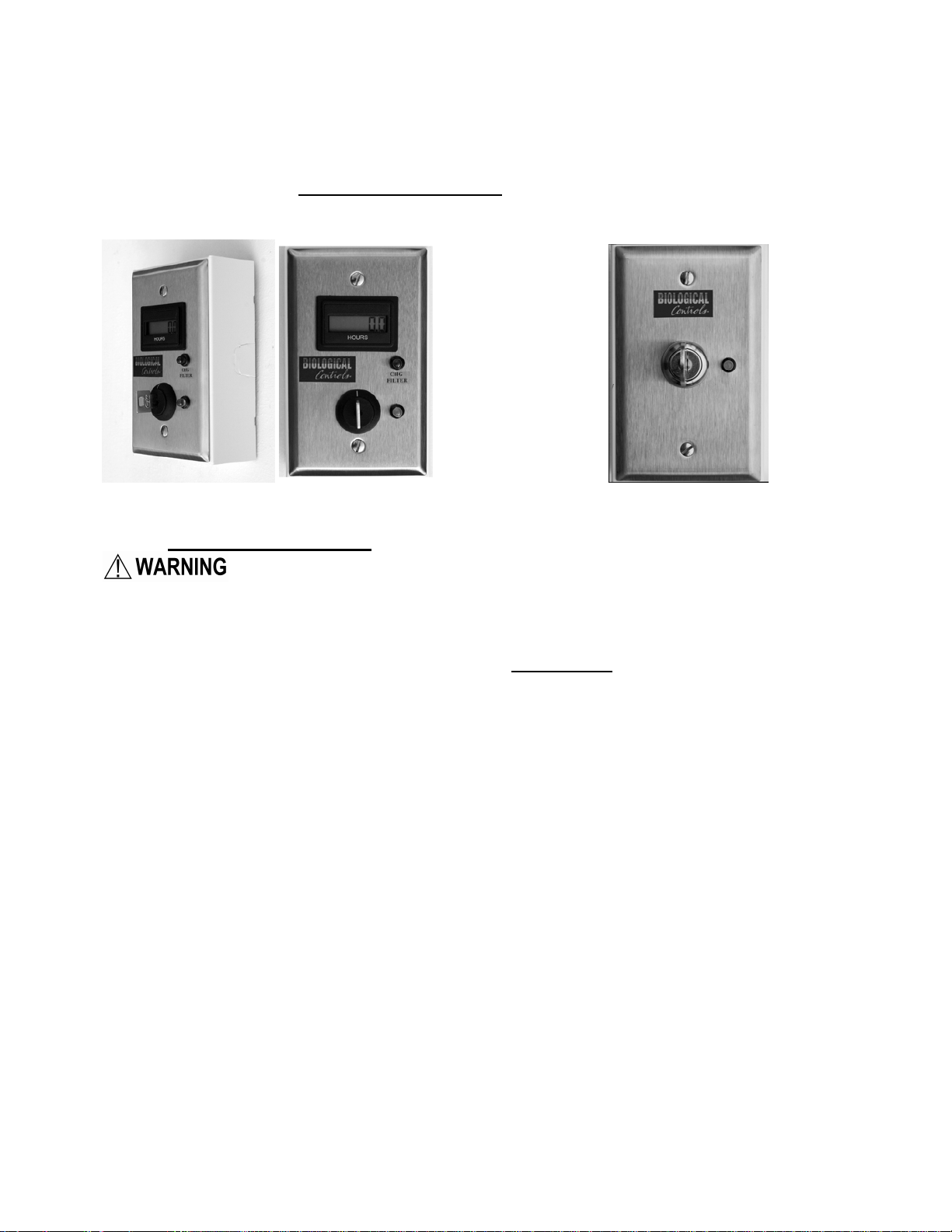
3.2.4. Wall Plate Control Unit (optional)
The Filter-Module is equipped with a 30’foot 3-conductor control cable (4-wire when a pressure
switch option is included). This cable can be lengthened by splicing it to a similar alarm or
thermostat-type (18-22ga.) cable.
A 24VDC universal input power-module is supplied with each Switch Plate Control Unit. The
power-module output can be spliced into the cable at any point in the run. It must be plugged into a
facility AC power source that will not be interrupted during normal activity. Note that the polarity
(+,-) of the power-module 24VDC must be observed as shown in the schematic for proper
operation. The module positive (+) wire is marked with a white-ink dashed line.
Copyright 2010 Biological Controls 5 8/19/2010
Some Filter Modules are equipped with an optional internal 24VDC power module. When
equipped do not use an external unit described above. See the Schematic wiring for each option in
the Appendix.
3.2.5. Key-Switch (optional)
The Key Switch provides only an on/off - key-switch and a LED power indicator.
Switch Plate Controller Key Switch
4. SYSTEM START-UP
After electrical wiring is completed and before applying power to the system, check the
ground (earth) wiring continuity to all of the components per the electrical safety
requirements.
Note: UV units are shipped with the lamps uninstalled and packaged inside the
chassis. The lamps should be installed into their sockets before starting the system
to avoid having to remove the HEPA filter to gain access.
When the system components have been mounted and all of the duct-work and electrical wiring
connections have been completed, the system is ready for operation. Use the on/off switch located
on the Filter Module face-plate or use the optional wall mounted remote switch (note the Filter
Module power-switch must always remain “ON” when used with any remote control switch
option). When powered, the hour-meter will start recording system run-time (the decimal-point
blinks). The mini-helic pressure-gauge will register the filter resistance and the Filter Module
power-switch will illuminate.
Note: When the UV lamps in the EXC7-UV are operating properly a view-port on the faceplate
will glow blue.
For negative-pressure environments (see the System Applications Section), adjust the damper in
the transition-box to achieve the desired room-pressure. (Note: A pressure monitor will be
necessary for this procedure. Wall mount and portable units are available from Biological
Controls.)

Copyright 2010 Biological Controls 8/19/2010
6
5. MAINTENANCE INFORMATION
Remove power from the Blower Module before starting maintenance
routines. Procedures involving electrical wiring should only be performed by
qualified electricians.
5.1. Blower Module
The Blower Module requires no maintenance since it is equipped with permanently lubricated
bearings. The facility power is connected to a circuit-breaker (fuse for 1/5 HP option) mounted in
this module. The breaker/fuse should never open during normal operation. Always consult an
electrician if the breaker/fuse opens since this usually indicates a more serious electrical problem.
5.1.1. Blower Removal
In the unlikely event the blower must be removed from the Blower-Module chassis follow these
steps:
•Remove the intake collar plate from the blower box by removing the screws around the
periphery. Disconnect the internal power cable (three (3) conductors connecting the motor
to the Blower-Module electrical box. This cable will be reused if a new motor is installed.
•Use a ¼” inch hex socket to unfasten the four #6 sheet-metal screws that connect the blower
exhaust-port to the blower chassis.
•Remove the six (6) ¼-20 hex-head bolts holding the blower motor-mounts to the chassis.
The blower along with the motor mounting feet can now be withdrawn from the blower
chassis for repair or replacement.
•Transfer the mounting feet to the new motor using the same hardware. Reinstall in the
reverse order.
5.2. Filter Module
The Filter Module contains the HEPA and Pre-filter media that requires renewal when indicated by
the Air Pressure Gauge or optional Air Switch change-filter LED mounted on the wall mounted
control unit. When the Air Switch option is not provided the Wall Switch Control Plate will not
include the “Chg Fltr” Red LED.
All units are factory tested and meet or exceed both Electrical Hi-Pot and Particle-Count (99.997%
clean exhaust-air @ .3micron particle size) tests per FDA requirements. A ¼ inch diameter probe-
port is accessed by removing a plastic snap-in cover in the center of the rear panel chassis-cover
when field testing is required.
The UV lamps require change-out every 8000 hrs (approximately 1 year) of continued use. Log the
Hour-Meter readings to determine the UV maintenance schedule. The UV view-port mounted on
the control panel will glow blue when the UV bulbs are active.
Copyright 2010 Biological Controls 8/19/2010
7
5.2.1. Cleaning
Wipe the face of the stainless steel Filter Module grille periodically. This is attributable to dust
being attracted by static charge to the grille face before being captured by the pre-filter. A stainless
steel cleaner, mild detergent or alcohol will do the job.
Do not get the filters wet. The filters are not reusable and must be disposed of when loaded.
The UV lamps only require cleaning during the installation process to remove finger oils. Never
attempt to clean the UV lamps when mounted inside the unit. If cleaning is necessary always
remove the lamps from the Filter Module chassis.
5.2.2. Hour Meter
The meter is equipped on the Filter Module and one is also standard on the Switch Plate Control
unit. The meters are activated whenever the blower-fan is operating. The LCD display is always
on to show continuous hours of system run-time. The decimal-point will flash when the system is
running. An internal non-replaceable battery powers the meter for 5-8 years of continuous use. If
the display goes blank when power is turned off it indicates that the meter requires replacement. A
new meter is available from the factory. It is easily replaced by removing the four (4) screws that
secure the control panel, pressing out the old unit and inserting the new one, and finally reinstalling
the panel to the Filter Module chassis. The meter does not have a reset function to prevent
inadvertent resets. Always log the meter readings on the Filter Module label after maintenance
activity.
5.3. Filter Renewal
5.3.1. Pre-Filter
Whenever renewing a pre-filter or when performing any maintenance procedure where
personnel may come into contact with a filter or contaminated surfaces surrounding the
filter-chassis, wear approved face masks, latex gloves, and follow the contamination cleaning
and waste-disposal rules and procedures of the facility.
Filter replacement is necessary when the Minihelic pressure-gauge increases by .1” WC of the
value when the filter was new. This, on average, is every 3-4 months of continuous use.
Open the swing-down stainless steel filter access door by depressing the two ball button-latches.
The door is now free to swing down. Remove the old filter from the door recessed area and replace
it with a new one. Close and secure the door by making sure the two button-latches are engaged.
Log the maintenance activity and hour-meter reading on the door label.
5.3.2. HEPA Filter
Replacement is necessary when the pressure gauge increases by a reading 50-60% greater than
when both filters were new (generally readings above 1.5”WC). The average usage time of the
HEPA is 12-18 months of continuous use.
When handling a new HEPA filter, hold it by its external frame without touching the media.
Temporally place cardboard over the entire room-side face of filter to protect the media
during the procedure. Remove the protective cardboard just before the filter clamps are fully
tightened.
Copyright 2010 Biological Controls 8/19/2010
8
The HEPA filter is replaceable from within the room. Open the swing-down stainless steel door
by depressing the two ball button latches. Once the HEPA filter is exposed, loosen the four (4)
filter clamp-nuts but do not remove them or the clamps from the threaded-rod. Use a 7/16-inch
deep-socket on an extension to loosen the nuts and position them to the end of the threaded-rods
that run through the clamps.
The HEPA filter drops out of Filter Module after twisting the loosened clamps away from the filter
body. Place a plastic bag, large enough to cover the swing down door and the HEPA filter, and
drop the filter into the bag. Seal the bag and dispose of according to facility procedures.
Depending upon the length of time the filter has been in place, it may be necessary to pry it loose
from the framework. Caution must be exercised to prevent damage to the Filter-Module chassis
during the extraction. The HEPA filter is of no value for reuse, so damage to the filter while
handling is inconsequential, although caution should be exhibited to prevent contaminant exposure.
Clean the area where the HEPA gasket makes contact with the Filter Module Chassis surface to
remove debris using alcohol.
Support the new HEPA inside the threaded-rods by twisting the filter clamps to fit around the filter
body. The HEPA gasket should face into the Filter Module. Check the HEPA gasket to make sure it
is compressible and not damaged.
The filter media is very fragile and can be damaged easily. Be careful not to touch or puncture the
HEPA filter face. If the media is ruptured or punctured, it is important to replace or repair it
immediately, by a qualified individual, using approved methods.
Secure the filter in place by tightening the filter clamp nuts. Tighten the nuts until the gasket is
compressed by approximately 50-60%. DO NOT over tighten.
NOTE: HEPA and pre-filters are disposed of after use. They are not washable or cleanable
and cannot be reused. Treat as contaminated.
5.4. UV Lamp Renewal
For EXC7-UV models only
(Replacement Part No. UB-002)
DO NOT EXPOSE EYES OR SKIN TO UVC LIGHT FROM ANY
SOURCE. DO NOT VIEW UV LAMPS WITHOUT USING PROPER EYE AND SKIN
PROTECTION.
Oil and dirt from fingerprints or other sources will permanently etch the
quartz-glass of the lamp and weaken the structure. Always clean lamps outside of the chassis.
Use of incorrect lamps can result in damage to the ballast, LAMP AND
compormise the function of the filtration unit.
A UV lamp contains a small amount of mercury. If the lamp breaks, clean and
dispose of with care according to your facility regulations. Make sure all glass fragments
have been removed from the unit before starting the blowers.
Never attempt to replace lighted UV lamps. When changing UV lamps, use
approved UV eye and skin protection.
UV lamps require renewal every 8000 hours (approx. 1 year) of operation. Check the Hour-Meter
Log to determine a routine maintenance schedule.
Copyright 2010 Biological Controls 8/19/2010
9
To access the UV lamps, open the filter access door and remove the pre-filter and HEPA as
described in the filter renewal process. The lamps are bi-pin type and twist in and out of the
connectors. Replace all lamps at the same time, dispose of properly.
Power the module momentarily to test the lamps. Follow all of the Safety notices above. If all
lamps are working remove power and reinsert the HEPA and pre-filter following the filter renewal
instructions above. Secure the swing down door, log the maintenance activity, and reactivate the
system.
6. System Applications
6.1. Creating A Negative Pressure Room
Negative pressure will be achieved when more air is exhausted from the room than is entering it
(CDC Guidelines state that room exhaust-flow should be either 10% or 50 cfm greater than the
supply to achieve negative pressure). The most recent guidelines call for pressure differential of
negative .010” H2O (W.C.) or minus 2.49 Pascal’s.
The room must be sealed well and leak-free (especially the ceiling) to create a negative
pressure environment. This allows air to only enter the room from the opening under the door,
the corridor or a designated positive pressure area.
When exhausting directly to the outside, it is advisable to place the Blower Module as close to the
exit vent as possible. The longer the total length of the ducts and the more bends and turns in the
ducting, the higher the air flow-resistance and conversely the lower the exhaust air-volume (CFM).
To create negative pressure within a room (the room pressure is less inside the room than in the
surrounding areas) the MICOCON® EXC7 components are placed in any ceiling location that
makes it convenient for attachment to the nearest exhaust duct or outside wall. The length of all
duct-runs should not exceed 12 feet and the total duct-rise should not exceed 10 feet. Since the
exhaust-air has been filtered it is possible to exhaust directly into an air-return area above a sealed
ceiling.

Copyright 2010 Biological Controls 8/19/2010
10
6.2. Room Filtration Only
The system can be used to filter and recirculate air within a room. (The transition-box and exhaust
duct would be removed in the above example and the blower 12”duct is used to connect directly to
the ceiling diffuser.)
In this application, the clean air from the exhaust will be returned to the room through one or more
ceiling diffusers. The best placement for the Filter-Module intake would be above the area
generating the source of contamination. The room diffuser(s) should be placed 6-8 feet away from
the filter-module intake to prevent "short circuiting" the filtered air. This distance will allow
adequate space for the reintroduction of the air back into the room, providing better filtration and
dilution; thereby, increasing the effectiveness of the in-room air changes.
7. FACTORY RETURNS (RMA)
Before shipping any component to the factory, a Return Material Authorization (RMA) Number
must be issued for units under warranty. For units out of warranty, a written purchase order must
be issued to Biological Controls prior to the return. The factory will NOT accept and will refuse
any merchandise returned without proper authorization. The factory is not responsible for any
damage to or loss of merchandise during return shipping. DO NOT RETURN
CONTAMINATED FILTERS TO THE FACTORY.
8. WARRANTY
Limited Warranty:
Biological Controls warrants that the product is free of defects in workmanship and materials
during normal use and service for a period of Twelve (12) months from the date of purchase by the
original end-user.
If at anytime during the warranty period the product is defective or malfunctions, Biological
Controls or its dealer or distributor, from whom the product was purchased, shall at the option of
Biological Controls replace or repair the defective part or component.
This warranty shall not apply if it is shown that the defect or malfunction was caused by damage
due to shipment, improper electrical connections, or improper use or abuse of the product.
The sole responsibility of Biological Controls shall be to repair or replace the product within the
terms stated above. Biological Controls shall not be liable for any loss or damage of any kind,
including any incidental or consequential damages resulting, directly or indirectly, from any breach
of warranty, expressed or implied, or any other failure of this product. (Some areas do not allow the
exclusion or limitation of incidental or consequential damages, so this limitation may not apply to
you.) The warranties set forth are exclusive and Biological Controls expressly disclaims all other
warranties, whether written or oral, implied or statutory, including but not limited to any warranties
of merchantability, workmanship, or fitness for a particular use.
In our continuing effort to produce the highest quality products, we reserve the right to change or
alter product specifications and materials without notice.
This warranty gives you specific legal rights and you may have other rights, which vary, from state
to state or country to country.
8.1. Making a Warranty Claim
To make a warranty claim or if you have questions about the warranty policy, contact the
distributor from whom you purchased the product.
NOTE: Do not return any products or components directly to the factory without a factory issued
“Return Merchandise Authorization (RMA) number” issued by the Biological Controls Customer
Service Department.

Copyright 2010 Biological Controls 8/19/2010
11
Manufacturer: TEL: 800-224-9768
BIOLOGICAL CONTROLS FAX: 732-389-8821
749 Hope Road Suite A WEB SITE: www.biologicalcontrols.com
Eatontown, NJ 07724
Copyright 2010 Biological Controls 8/19/2010
12
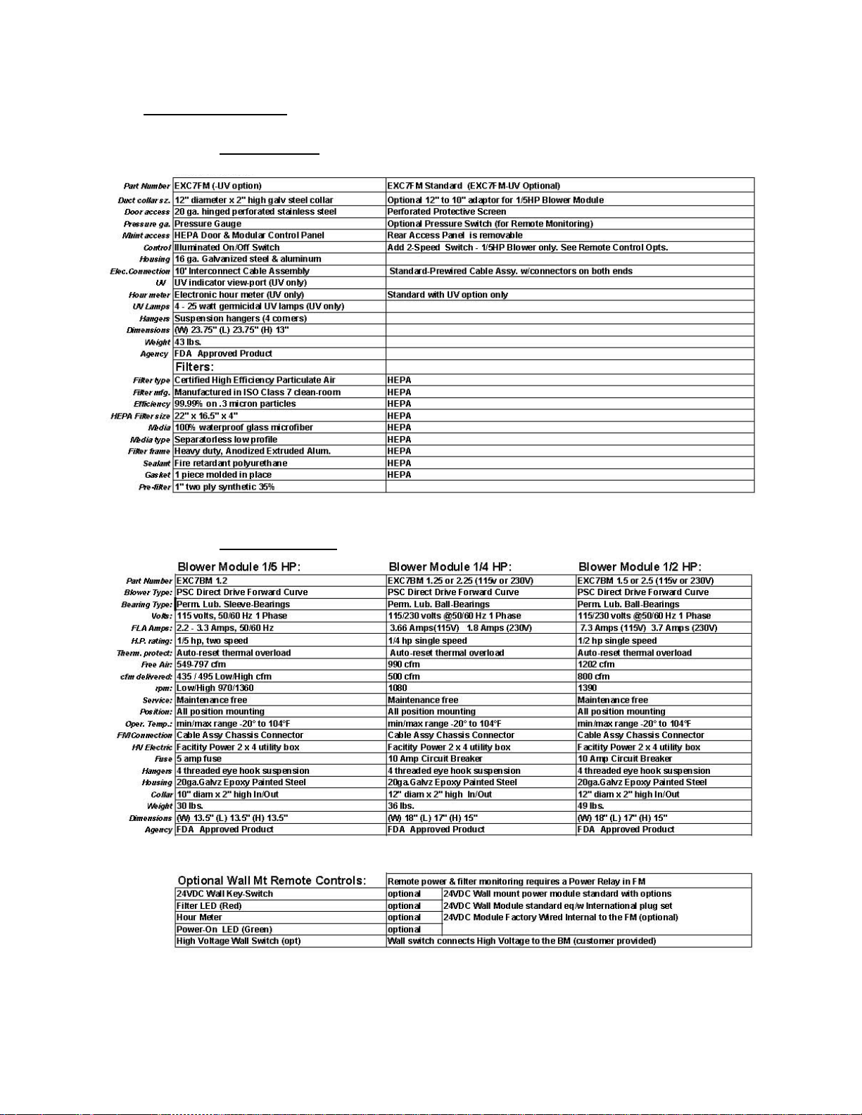
9. SPECIFICATIONS
9.1. Filter Module
Feature Description
9.2. Blower Modules

Copyright 2010 Biological Controls 8/19/2010
13
10. ASSEMBLY FIGURES & DIMENSIONS
10.1. Filter Module

Copyright 2010 Biological Controls 8/19/2010
14
10.2. Blower Module
Copyright 2010 Biological Controls 8/19/2010
15
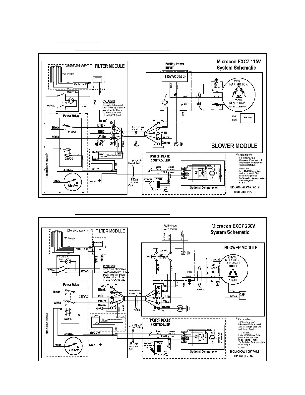
11. SCHEMATICS
11.1. Typical System 115V Schematic
11.2. Typical System 230V Schematic
This manual suits for next models
1
Table of contents


