Bionics BFM-900L User manual

Operation Manual
BFM-900L
FETAL MONITOR (Ver 1.1)
Head Office/Factory
687-5, Sangoan-ri, Hongcheon-eup, Hongcheon-gun,
Gangwon-do, Korea (zip.250-804)
Tel : +82-33-434-9041 Fax : +82-33-434-9043
Seoul Office/R&D
1406, Masters Tower, 553, Dohwa-dong, Mapo-gu,
Seoul, Korea (zip.121-748)
Tel : +82-2-714-2960∼2 Fax : +82-2-714-2963
Customer Service Dept.
Tel : +82-2-714-2962 Fax : +82-2-714-2963
Address of Region Representative
ET MEDICAL DEVICES SPA
VIA DE ZINIS 6, 38011 CAVARENO (TN) ITALY
Tel : +39 0463 85 01 25 Fax : +39 0463 85 00 88

BFM-900L
FETAL MONITOR (Ver 1.1)
(MAR. 27. 2009)
OPERATION MANUAL

Introduction
General
Warranty Period
Service Request
How to contact us
Chapter 1. How to use the User’s Manual
1.1 General
1.2 Contents
1.3 Meaning of Symbols in the User’s Manual
Chapter 2. Precautions for Us
2.1 Precautions for Using-Environment
2.2 Precautions for Electric Safety
2.3 Maintenance and Cleanness
Chapter 3. Overview of BFM-900L
3.1 Principle and Features of BFM-900L
3.2 Composition
3.3 Parts
3.4 Symbols
3
3
4
5
6
7
7
7
8
9
9
11
12
13
13
13
14
17
Table of Contents

Chapter 4. How to install BFM-900L
4.1 Precautions for Installation
4.2 Installation of Main Body
4.3 Cable Connection
4.4 Pinter Paper Loading
Chapter 5. How to use BFM-900L
5.1 Before using BFM-900L
5.2 Using BFM-900L
5.3 Basic Screen
5.4 Functions of Keys
5.5 Measurement of FHR and UC
5.6 How to use Event Mark
5.7 How to use the printer
5.8 Volume Control
5.9 Alarm On/Off
5.10 Sound
5.11 AST(Optional)
Chapter 6. Setting by Menu Function
6.1 Record Setting
6.2 Alarm Setting
6.3 Volume Setting
18
18
18
19
21
22
22
22
23
24
25
29
30
32
34
35
35
36
38
41
43
6.4 Time Setting
6.5 Default Setting
Chapter 7. Solution for Precaution and Warning
Chapter 8. Power
8.1 AC Power
8.2 Battery Power(Optional)
Chapter 9. Simple Troubleshooting
Chapter 10. Specification
45
48
49
54
54
54
56
57

General
3
BFM-900L
INTRODUCTION GENERAL
Thank you for buying BFM-900L (Fetal Monitor). For safe use, stable performance and follow-up
management, please read this manual before using the device.
Before using the device, please read this manual to perfectly understand the basic function, using
method and maintenance method of the device, so that you can assure the safe use and long-term
stable performance of the device.
We, Bionics, provide you with reliable products only.
The device shall be assembled/extended/amended/repaired by us or the person certified by us.
The device shall be installed meeting relevant regulations including electrical installation and etc.
The device shall be used in accordance with the User’s Manual.
The device shall be used under the direction of the person who is medically certified.
This device is used to monitor the fetus’s status.
For the patient’s safety, use only the parts and accessories recommended by us.
If you connect the device with any part or accessory not specified in the User’s Manual, you shall
notify it to us or any distributor who has the right to sell this product.

FETAL MONITOR
(Ver 1.1)
4
Warranty Period
Service Request
5
BFM-900L
SERVICE REQUEST
The service for Bionics products can be carried out by only Bionics Customer Service Dept or the
person certified of such service by Bionics. If the device is repaired or tried to be repaired by any
person other than such certified person for the warranty period, the warranty period shall be void.
Bionics Customer Service Dept or any distributor certified of Bionics Product Service is obligated
to carry out any service requested by the user.
If you find any problem on the device or any risk on the human body in any hospital and place
where the device is used, the maintenance/repair work shall be promptly and fully taken.
If you find any problem on the device, take the actions as follow:
Please immediately contact our Customer Service Dept or any distributor representing us for
our service. Check the model name, product number, purchasing date, problem or question to
ask before contacting us.
Our Customer Service Dept will check and solve the problem online first. If difficult to solve
the problem online, it will visit you to solve the problem immediately.
WARRANTY PERIOD
This product is made through strict quality management and test process. This product can be
repaired, replaced or refunded in accordance with “Consumer’s Damage Compensation
Regulation” noticed by Economic Planning Board.
This product is warranted for 1 year.
If broken while being used normally, this product will be freely repaired by our service center
for such warranty period.
If you find any problem on the device, please let us know the model name, device number,
purchasing date and breakage content.

FETAL MONITOR
(Ver 1.1)
6
How to Contact Us How to use the User’s Manual
7
BFM-900L
CHAPTER 1 How to use the User’s Manual
1.1 General
This device provides you with the exact and stable values (fetus’s heart rate, patient’s uterus
shrinking level and etc) measured on the patient and fetus and correct information of the
fetus’s status.
This manual covers BFM-900L, a Fetal Monitor manufactured by Bionics, which is
designed for maximal user’s convenience. This manual consists of independent chapters.
Some information is specified several times here in this manual.
This manual is a guidebook for efficient use of BFM-900L. For clinical and pathological
information about the device, please refer to basic relevant medical books. Then, you will use
the function of the device better. If you refer to clinical books together with this manual, you
will expect more effects from using the device.
If you find any Problem while using, please contact us or our A/S Reservation Office.
1.2 Contents
The user must read the User’s Manual before using the device.
This manual consists of the chapters as follow:
Chapter 1. How to use the User’s Manual
Chapter 2. Precautions for Use
Chapter 3. Overview of BFM-900L
Chapter 4. How to install BFM-900L
Chapter 5. How to use BFM-900L
Chapter 6. Setting by Menu Function
Chapter 7. Solution for Precaution and Warning
Chapter 8. Use of Power
Chapter 9. Simple Troubleshooting
Chapter 10. Specification
HOW TO CONTACT US
BIONICS Co., Ltd.
Tel : 82-2-714-2962
* Before making reservation on troubleshooting, please check the
model name, serial number, purchasing date and abnormality of the
damaged product.
Customer
Center
Please contact us at the following number to get various kinds of service, product information and
etc and to talk to the person in charge of sales.
Bionics service is always open to you. Please contact us at the number as follows:

Precautions for Use
9
BFM-900L
FETAL MONITOR
(Ver 1.1)
8
How to use the User’s Manual
CHAPTER 2 Precautions for Use
2.1 Precautions of Using-Environment
Avoid using or storing the device under the environments as follow:
Keep it away from wet place or
do not use it by wet hands.
Avoid areas that have high fluctuations
in temperature. (Temperature Range for
Use: 10℃~45℃, Humidity: 30% ~ 85%)
Avoid areas of high humidity or
ventilation problems
Avoid areas susceptible to
large shock or vibration
Keep it away from any electric
heater.
Keep it away from direct
sunlight.
1.3 Meaning of Symbols in the User’ s Manual
We have marked on the user manual to emphasize the following agreements. The user must
follow all warnings and remarks.
In case of improper use or poor maintenance on the equipment resulting in product defect,
neither the manufacturer nor the distributor will be responsible for any damages.
“WARNING” is used to notify the possibility of critical injury, death, and physical and
financial damage in case the warning is ignored
“PRECAUTION” is used to notify the possibility of non-critical injury in case the notice is
ignored
“Note” is used to notify users of not dangerous but very important information regarding
equipment installation, usage, and maintenance

FETAL MONITOR
(Ver 1.1)
10
Precautions for Use Precautions for Use
11
BFM-900L
2.2 Precautions for Electric Safety
Before using the device, please check the items as follow:
Is the power supply line of the device proper? (100 - 240VAc).
Is every connection part (power line or any optional device) connected to the device properly?
For correct connection method, see the Chapter 4.
Is the device completely grounded?
(Otherwise, noise may be made.)
To avoid electrical noise or disturbance, install the device away from generators, X-ray devices,
broadcasting devices, and idle wires. Inaccurate reading may show in case above mentioned
devices are nearby. The BFM-900L requires a separate power source and stable connection.
Inaccurate reading may show in case these devices are sharing the same power line.
BFM-900L is classified as follows:
- This device is I type-BF grade device in terms of electric shock.
- It is improper to use this device nearby inflammable anesthetic and solvent.
- IEC/EN 60601-1 (Safety of Electric Medical Equipment) based noise making is A class.
IEC/EN 60601-1-2 (Electromagnetic Compatibility Requirements) based noise proof is B level.
Avoid areas near
chemicals or explosive gas
Do not disassemble it.
We WILL NOT be responsible under
any circumstances in this case.
Hold the plug to withdraw the
power cord.
Do not power it on before
completely installed.
Otherwise, it may be damaged.
Do not submerge the probe for
5 hours or longer.
Make sure to not let any dirt or
especially metallic objects from
going inside the equipment
Basic environments for use are as follow:
Temp : 10℃~ 45℃
Pressure : 70 ~ 106 KPa
Humidity : 30% ~ 85%
Basic environments for storage are as follow:
Temp : -10℃~ 50℃
Pressure : 70 ~ 106KPa
Humidity : 20% ~ 95%
IPX7
(DOP, UC Probes)
If you connect other devices to use RS-232C port, you should use the devices which are satisfied
with standard EN60601-1.

Overview of BFM-900L
13
BFM-900L
FETAL MONITOR
(Ver 1.1)
12
Precautions for Use
3.1 Principle and Features of BFM-900L
BFM-900L is a Fetal Monitor, which basically measures the fetus’s heart rate and the patient’s
uterus shrinkage. BFM-900L sends supersonic signal to the patient’s abdomen and then measures
the signal returned from the fetus’s heart. It then sorts out the Doppler frequency from the returned
signal and converts it into the heart beat of the fetus. The signal is then analyzed and displayed as
the fetus’s heartbeat and printed out on a printer. The patient’s contraction level of uterus can be
measured with pressure sensors, as well as printing out the data to inform the level of her labor
pain and frequency. BFM-900L is that the adjustments and values of the signals can easily be
controlled with simple key controls. BFM-900L is capable of measuring twin fetus, and supports
an optional central monitoring system on serial communication. It is also available AST(optional)
function.
3.2 Composition
Basic Accessories
- Supersonic Probe (DOP) (2EA)
- UC Probe (1EA)
- Event Mark Jack(1EA)
- Printer Paper (1EA)
- Power Cord (1EA)
- 110V AC Conversion Jack (1EA)
- User’s Manual (1 Volume)
- Supersonic Gel(1EA)
- Belt for Probe Fixation (3EA)
Options
- Central Monitoring Device Cable/Communication Program
- Cart
- AST Probe
- Internal Battery
2.3 Maintenance and Cleanness
You can maintain cleanliness on BFM-900L and its accessories (including the probe) in various
ways. Use the method provided below to avoid damage or contamination on the equipment.
If you use materials that can damage the product, (non-approved cleaning material) the warranty
will be voided.
Using warm water, clean the main body with alcohol on a soft cloth at least once a month, and do
not use lacquer, thinner, ethylene, and acidic cleansers. These materials can damage the device.
The cable and accessories must be maintained to avoid contact with dirt and wiped down with
warm water (approximately 104℉) on a cloth pad, and use alcohol to clean it once a week.
Do not dowse the connection parts of the accessories in liquid or detergent. Also, no liquid must
go in the connection part of the device or the accessories.
After cleaning the device, check the main body and the sensors very carefully.
If the device is overused and damaged, do not use it.
CHAPTER 3 Overview of BFM-900L

Overview of BFM-900L
15
BFM-900L
FETAL MONITOR
(Ver 1.1)
14
Overview of BFM-900L
■Left Face
(1) Handle for Carriage (2) DOP1 Probe Connection Part
(3) DOP2/AST Probe Connection Part (4) AC Power Switch
(5) Mark Jack Connection Part (6) UC Probe Connection Part
(7) ID Label
(1) Display for FHR 1 Value (2) Display for FHR 2 Value
(3) Display for Alarm setting (4) A/C & Battery Power LED
(5) Warning On/Off Key (6) Display for UC Value
(7) Display for Printer setting (8) Key Control Panel
(9) 4˝Printer (10) Alarm LED Lamp
3.3 Parts
■Front Face & Control Panel

Overview of BFM-900L
17
BFM-900L
FETAL MONITOR
(Ver 1.1)
16
Overview of BFM-900L
3.4 Symbols
■Rear Face
(1) Handle for Carriage (2) Adapter Power Connection Part
(3) Ground Terminal (4) AC Power Connection Part
(5) RS-232C Cable Connection Part
Do not disassemble the device. Otherwise, you may be electrically shocked. The device shall
not be disassembled by other than the person qualified for our product service.
Symbol Description Symbol Description
15V-3A DC Power Input
Type BF Device,
Electric Shock Device
Protection
Warning or Precaution
(See the User s Manual.)
AC Main Power On/Off
DOP1 Probe Connection Part
DOP2 Probe Connection Part
UC Probe Connection Part
Mark Jack Connection Part
Ethernet Connection Terminal
Working by AC Input
Working by Battery
Print Start/End
UC Reference Setting
Display
Volume Control
Back to Default Screen (Exit)
Setting Change
Setting Change
Save the Setting
Back to Menu mode
DC Communication Port
AC Power Input Part
Terminal for Equipotent by
Connection of Each Part of
Device/System without
Necessity of Ground
Potential

How to install BFM-900L 19
BFM-900L
FETAL MONITOR
(Ver 1.1)
18 How to install BFM-900L
4.3 Cable Connection
1) Power Connection
Stick the Power Cable into BFM-900L Power Connection Terminal and change the Power Switch
of the left face into “O”status. Then, the device is powered on. If you cannot use the power cable,
you can use DC adaptor which suggest DC15V and 3Amp.
2) Connection of Main Body with Probe
- Connect the probe desired to be measured to the connection terminal part on the left face of the main body.
- If not properly connected, problem may occur.
CHAPTER 4
How to install BFM-900L
4.1 Precautions for Installation
Precautions for Installation of BFM-900L:
- BFM-900L shall be used at the ambient temperature of 10°~45°and humidity of 30% ~ 85%.
- Check the connection status of Power Cord.
- Do not plug various cords into an electric consent.
- Place the main body on flat place.
- Ground it. (Otherwise, noise may be made).
- Do not use an electric cord that may generate noise.
- Probe may be damaged by impact. Do not get the Probe externally impacted nor submerge it in
water or oil
- If Supersonic Probe used, it must be used with Supersonic Gel. After use, wash it clearly and store it.
- Install it considering the ambient temperature and humidity. Keep it away from dusty or
inflammable substances.
- All configuration settings are stored without demonstration setting in the internal memory even
after the device is powered off and then turned back on. However, if the device has not been
used for over ten years or an external shock is applied to it, the stored data may be altered, and
you must reconfigure the information.
4.2 Installation of Main Body
BFM-900L is designed to be easily used on a normal table, cart, or any other appliances
commonly found in a hospital environment. Normally, you can use the handle in the back of the
device and place it on a flat surface. Since the center of gravity of the device is low, key
manipulation on the device will not topple it over. It also does not slip.
We recommend the power cable than the adaptor. The adaptor which is DC 15V and 3Amp
is optional accessory.

How to install BFM-900L 21
BFM-900L
FETAL MONITOR
(Ver 1.1)
20 How to install BFM-900L
4.4 Printer Paper Loading
- In order to put the printing paper in the tray, push the buttons on the side of the front panel of the
printer door and pull forward.
- When you pull the door forward the door will open and you will see the area where you can place
the roll of printing paper, as well as the printer machine, and black roller on the inside of the door.
- Make sure the paper’s printing side is facing up and then close the printer door.
3) Ground Cable Connection
Connect the Ground Terminal of the main body with the Ground Terminal of the installation
place.
4) Serial Cable Connection
Connect the Serial Connection Part of the main body with the Serial Terminal of the installation
place.
Printer paper should be printed side upward. If not, it will not be printed on the paper.

How to use BFM-900L 23
BFM-900L
FETAL MONITOR
(Ver 1.1)
22 How to use BFM-900L
5.3 Basic Screen
(1) Displays Value of FHR 1
(2) Displays Heart Rate Rhythm of FHR 1
(3) Displays Heart Rate Rhythm of FHR 2
(4) Displays maximum limit of Alarm Level
(5) Displays Value of FHR 2 or Connecting Status of AST probe
(6) Displays minimum limit of Alarm Level
(7) Indicates bar graph of measured UC value
(8) Displays measured UC value
(9) Printer Status
(10) Offset Setting Status
(11) Printing Cycle for Printer Auto-Printing. Indicate remain print time during printing
CHAPTER 5
How to use BFM-900L
5.1 Before using BFM-900L
Check for following items before measuring the condition of the fetus.
Possibilities of any mechanical danger
Power plug and cable, and accessories
All items and equipment necessary to measure and inspect the condition of the fetus
5.2 Using BFM-900L
Connect the probe you want to use on the main body. Normal procedure is as follows.
- Pre-labor diagnosis for non-twin fetus : DOP I Probe, UC Probe, Mark Jack
- Pre-labor diagnosis for twin fetus : DOP I Probe, DOP II Probe, UC Probe, Mark Jack
- Wake up the baby : AST probe(optional)
Step 1) Turn on the Power Switch.
Step 2) Attach the probe to the patient. (Refer to 5.5, 5.6, and 5.7)
Step 3) Sound signal is heard.
Step 4) Measured signal is displayed on the FND as numbers.
Step 5) Record the measured readings with the print function.
Step 6) SETUP Key is used to modify the configuration. (Refer to 6)
Step 7) If you want to wake up the baby during measuring, please remove the Doppler from
DOP2 and connect AST probe(optional). Then press the button on the AST probe on the
patient’s abdomen. It makes sound for waking up the baby. Please do not close this device
to the ear. It makes you harmful.
“DO NOT CLOSE THE DEVICE TO THE EAR!”

How to use BFM-900L 25
BFM-900L
FETAL MONITOR
(Ver 1.1)
24 How to use BFM-900L
5.4 Function of Keys
■Keys on Front Face
■Lamp
The LED located on the key area of the front face Panel displays the status of the used Power.
(1) AC Power: LED lights up while AC Power being used
(2) Battery(Optional): LED lights up while Battery Power being used
■Alarm Lamp
The LED located on the top of the front face Panel displays Alarm and Heart Rate Rhythm.
5.5 Measurement of FHR and UC
Apply ample amount of Supersonic Gel on the surface of the Probe.
The DOP and UC Probe used in BFM-900L previous models are designed to be
used under water.
Doppler and UC probes are applied by IPX7 so they can be used for the underwater delivery
in the water.

How to use BFM-900L 27
BFM-900L
FETAL MONITOR
(Ver 1.1)
26 How to use BFM-900L
■Probe Connection
Connect DOP1, DOP2, and UC probes at the left side of the device. There are 2 Doppler probes
and you may connect them to any one of the DOP1, DOP2 and UC Terminals. When diagnosing
twin fetus, connect both terminals.
■Basic Screen by Probe Connection
If the DOP Probe is not attached, nothing shows on the screen where the heart rate is displayed,
and no sound or heart symbol signal shows.
If the DOP Probe is attached but not used, the status is Stand-By, and heartbeat area shows “---”
until the diagnosis starts. When the diagnosis starts, the calculated heartbeat shows on the screen.
If heartbeat is under 50 or heartbeat sound cannot be measured, heartbeat area shows “---”.
If the heartbeat displayed on screen goes over or under the alarm level limit, an alarm will sound
and alarm lamp will change green to red and FHR value will be twinkled.
Also, if the probe line is cut or the probe has been pulled off from the machine, and if it is disabled
during usage, each of the FHR on the FND will show “---”. “PRO OFF”and “d-1”, “d-2”, “UC”
will displays by turns in the maximum/minimum alarm level FND. The error code will also
displays in the Auto Print FND. And information sound(ding dong ding dong) will be heard.
Error Codes
-E1 : Paper Out during printing
-E2 : DOP1 Probe is disconnected during using
-E3 : DOP2 Probe is disconnected during using (If “E2”error occurs, it will not be displayed)
-E4 : UC Probe is disconnected during using (If “E2”or “E3”errors occur, it will not be
displayed)
-E5 : Low Battery (If “E2”, “E3”or “E4”errors occur, it will not be displayed)

How to use BFM-900L 29
BFM-900L
FETAL MONITOR
(Ver 1.1)
28 How to use BFM-900L
■FHR Measurement
(1) Touch the patient’s belly and search for the fetus°Øs back and place the DOP Probe. If the
fetus is positioned facing left or right, place the probe as shown on the picture.
If the probe is placed on the front of the fetus instead of the back, the focus tends to often
disrupt, and you may not get an accurate reading.
If the fetus is facing up or down, take extra caution to place the probe. Place the probe around
the patient’s navel.
(2) Move the probe slightly around and locate the area where the fetus’s heartbeat sounds the
loudest, and then use the belt to fasten the probe.
Do not adjust the volume until you have located an exact position with the probe.
Place the probe at the exact location, that is, an area where the heartbeat is heard loud and
strong, and the FHR heartbeat rhythm symbol blinks in sync with the fetus’s heartbeat, and then
adjust the volume.
(3) When using the belt to fasten the probe, make sure it does not slip.
As shown above, the probe cable going up in the direction of the patient’s head can prevent
damage to the cable and the probe does not move as much.
(4) It is important to apply ample amount of Supersonic gel on the probe surface to get rid of air
bubbles in between the abdomen and the probe.
(5) BFM-900L uses a Button-Top styled DOP Probe. Insert the protruding buttons on the opposite
side of the DOP Probe surface to the Button-Hole on the belt under the patient.
(6) It takes 4 to 5 seconds for the heartbeat to show. Once a stable heartbeat is displayed the
printing begins.
■UC Measurement
UC measurement uses an external attachable pressure sensor. Once the UC Probe is placed on the
patient’s abdomen, the pressure fluctuation of the patient°Øs uterus enables the contraction level.
(1) Place the belt underneath the back of the patient.
(2) Place the UC Probe on the highest point of the patient’s belly (Fundus: Usually about 10 cm
above the navel) or, the point on the patient’s belly where it has become the first place to
harden up.
(3) Insert the protruding buttons on the opposite side of the UC Probe surface to the Button-Holes
on the belt under the patient. The recommended tightness on the fastening of the belt is from
20 to 90.
(4) If the UC Probe is attached but not in use, a meaningless number displays on the screen. When
using the UC Probe, press the “Reference”key to reset the default value of 10 on the front
panel before use. BFM-900L shows the LED bar of uterine contraction level.
(5) Once a stable UC value is found, the printing begins.
5.6 How to use Event Mark
The purpose of the marking is to record the moment when the patient senses the start of the fetal
movement. When you press the Mark switch during printing an arrow shows on the printing
paper. Mark Jack is connected to the left connection terminal of the device.

How to use BFM-900L 31
BFM-900L
FETAL MONITOR
(Ver 1.1)
30 How to use BFM-900L
5.7 How to use Printer
The printer used in BFM-900L is a 4 inch Porti-M400V, made by Wooshim System. It uses 9V
Power and the width of the printing paper is 112mm.
■■Printer Operation
(1) “REC”indicator will turns on as red color after pressing the “Print”(or “Record”) key once.
And the FHR1, FHR2, UC, and the Fetal Movement (FM 1, FM 2) are recorded. FM will not
be recorded by the user’s menu setting.
(2) If you press the “Print”key once again the red colored LED will disappears and the recording
stops. The Printer scrolls out 1~2cm of extra sheet after the recording has stopped.
(3) The FHR 2 graph can be printed +20bpm more than the FHR 1 area. If you turn on the offset,
“Offset”indicator will turns on as green color
■■Auto Operation
(1) Control the print time. Print time is set by 10min, 20min, 30min, 40min, 50min, 60min and
off. If you use “OFF”, it will stop printing by press the “Print”button or out of paper.
(2) After finishing the setting by users, it will apply to the initial printing. This setting applies to
the “AUTO PRINT”area. This setting value is displayed the remained operation time.
■■FHR 2 Offset Operation
(1) Using 2 Probes simultaneously to measure FHR 1, 2, and the value comes out similar is when
it’s most effective. The Offset draws a graph by increasing +20bpm from the FHR 2 value.
(2) Before using the printer, use the “Up/Down/Enter”key to turn the Offset On.
(3) Once the “Offset : On”status is confirmed, another 20 is added to the FHR 2 value. After
finishing the setting by users, it will apply to the initial printing.
■■ZOOM Operation
(1) Use this function when you want to see the changes in the FHR more closely.
(2) When you select “On”in the “Zoom”category in the Print Setup, the FHR area is expanded
about 105 ~ 200 BPM than the normal range. After finishing the setting by users, it will apply
to the initial printing.
■■SPEED Operation
(1) Control the print speed.(1cm/min, 2cm/min and 3cm/min)
(2) After finishing the setting by users, it will apply to the initial printing
■■CONTRAST Operation
(1) Control the contrast of print by 3-step. High number is thicker to print.
(2) After finishing the setting by users, it will apply to the initial printing. This setting does not
apply during the printing. This setting also applies to the graph area.
■■FM Operation
(1) FM record on the paper is decided by setting.
(2) After finishing the setting by users, it will apply to the initial printing. This setting does not
apply during the printing. This setting also applies to the graph area.
■■Reading the Recorded Sheet
Press the “Print”key once to begin recording and the sheet ejects as described below.
The recording areas are divided into two main categories - the text area and the graph area. The
text and graph show as soon as the printing begins. The text is repeated at paper top area on 10
minute and is included the setup value of print-(1) Date (2) Time (3) Status of DOP 1, DOP 2
Probe and UC Probe (4) Status of FM (5) Print Speed (6) Status of Offsset and (7) Status of
ZOOM.
During printing, you cannot change the printer setting. If you want to change the setting, you
should stop to print.
Changed setting value without ZOOM is not changed even though you turn off the system.
Zoom is initialized after turning off.
How to use BFM-900L 33
BFM-900L
FETAL MONITOR
(Ver 1.1)
32 How to use BFM-900L
5.8 Volume Control
The volume can be adjusted in 8 levels and there are two ways to control it. One is to use the SETUP
key( ) and control it from the menu, and the other is to use the volume key( ). The
volume of Doppler I and II can be adjusted.
■Volume Change in the Menu
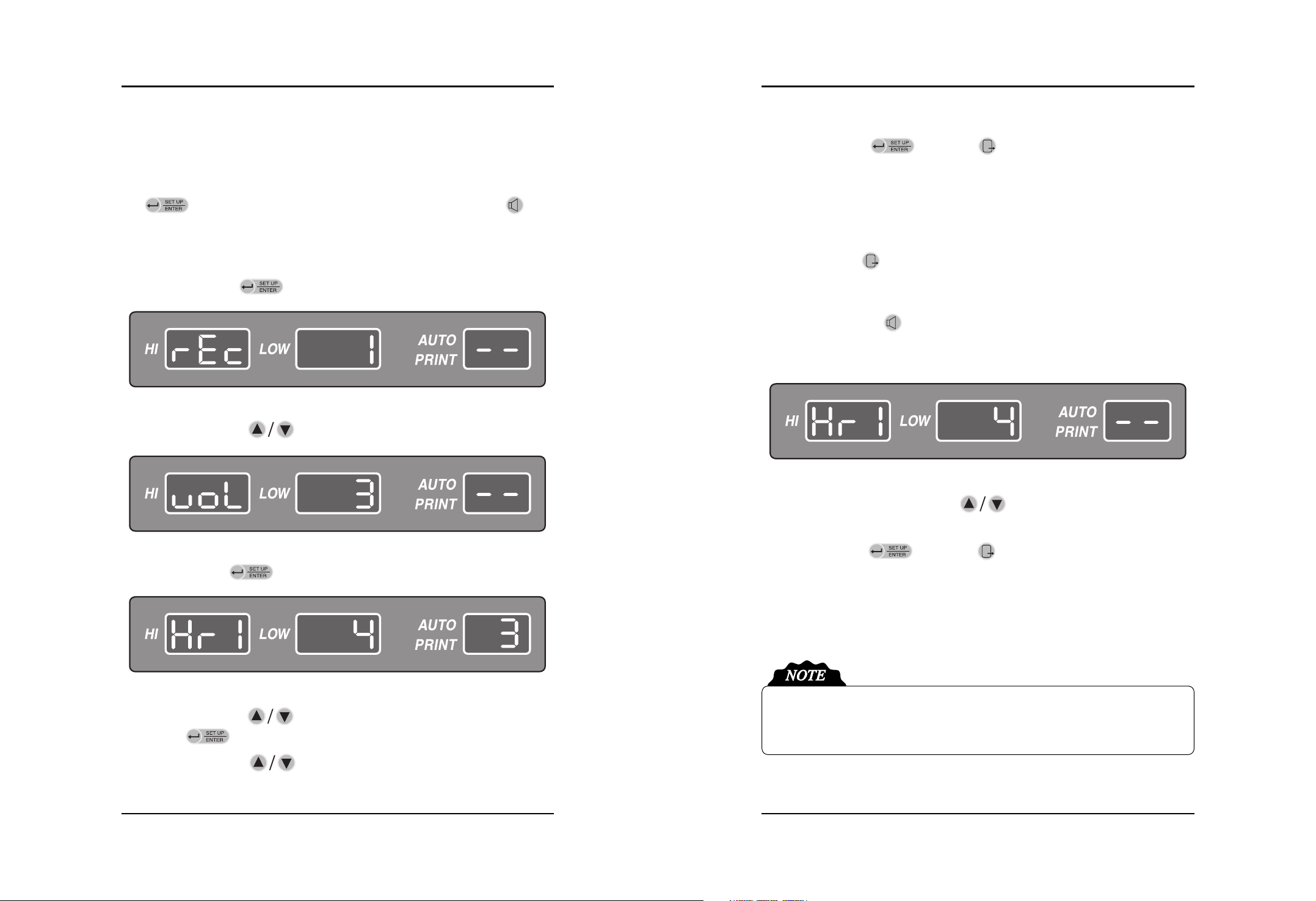
(1) Press the SETUP key( ) to move the menu setting mode.
(2) Press the Up/Down key( ) to move the volume menu.
(3) Press the Enter key( ) to enter the volume control area.
(4) Press the Up/Down key( ) for changing the volume HR1 or HR2 and then press the
Enter key( ). The volume level will be twinkled in the “LOW”area.
(5) Press the Up/Down key( ) to control the volume during twinkling.
The Volume of Key Sound, Alarm Sound and Information Sound cannot be adjusted. If the
alarm sound happens, you can turn off the sound to use SILENCE key. If the information
sound happens, you can turn off the sound to use Exit key.
(6) Press the Enter key( ) or Exit key( ) at the desired level and the volume control
operation is complete. If you press the Enter key, the desired level will be saved and move to
menu (3). If you press the Exit key, the volume level will be returned to previous level and
move to menu (2).
(7) You can change the volume level of DOP1 and DOP2 with process (2) ~ (6).
(8) Press the Exit key( ) and move to the basic screen after all setting.
■Using the Volume Key
(1) Press the Volume key( ) to move to menu setting mode. The initial setting is to control
DOP 1. If you press the Volume key once more, DOP 2 will be controlled. DOP 1 and DOP 2
are will be changed by the Volume key.
(2) Adjust the volume to use Up/Down key( ) after choosing DOP 1 or DOP 2. DOP 1
or DOP 2 can be adjusted to repeat process (1) and (2).
(3) Press the Enter key( ) or Exit key( ) at the desired level and the volume control
operation is complete. If you press the Enter key, the desired level will be saved. If you press
the Exit key, the volume level will be returned to previous level.
Table of contents


