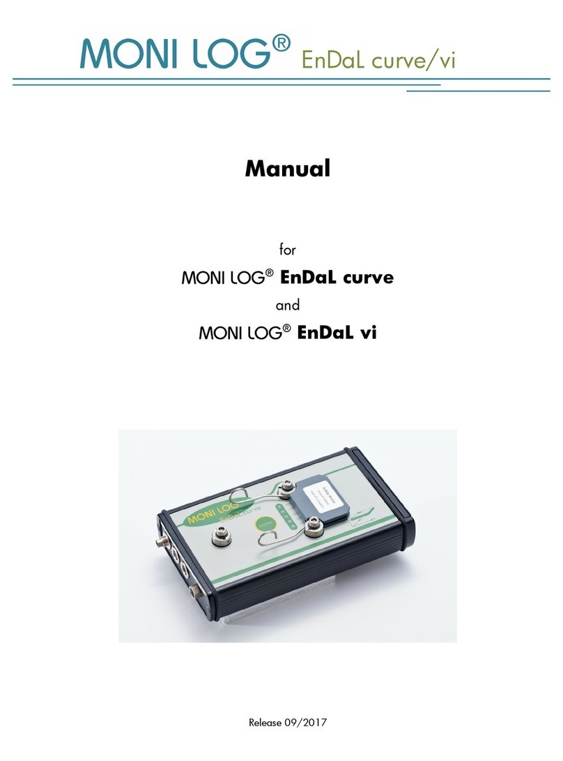
BIOPAC Systems BioNomadix Smart Center User manual

12.28.2017
BioNomadix
®
Smart Center
with AcqKnowledge
Guide
42 Aero Camino, Goleta, CA 93117
Tel (805) 685-0066 | Fax (805) 685-0067
info@biopac.com | www.biopac.com
www.biopac.com BioNomadix Smart Center with AcqKnowledge Page 1 of 24
BIONOMADIX SMART CENTER
Congratulations on your purchase of a BIOPAC BioNomadix Smart Center and welcome to the BIOPAC
community of researchers and educators –BIOPAC is confident that Smart Center will be a useful and vital
addition to your lab.
What is Smart Center?
BioNomadix Smart Center is a small-form data acquisition unit and wireless receiver that connects to a computer
USB port and records simultaneous physiological data from up to three BioNomadix Transmitters. Unlike
standard BioNomadix Systems requiring multiple receiver units connected to an MP Data Acquisition System,
Smart Center offers a compact, all-in-one data acquisition solution. Smart Center does not contain a battery and is
entirely powered by a computer USB port. No additional components or amplifiers are necessary. All that is
needed to record high quality data is the Smart Center, AcqKnowledge software, and transmitter(s).
Transmitter pairing and setup is configured in an easy-to-use AcqKnowledge Setup Wizard with guided prompts.
Smart Center supports all BioNomadix Transmitter types. When connected, Smart Center appears in the
AcqKnowledge hardware menu as a stand-alone hardware option, and supports most of the same advanced
software features as BIOPAC’s MP160 and MP36R Research Systems.
Smart Center functionality can be extended via the integrated I/O port, which provides access for up to up to 8
TTL digital channels. This is useful for recording synchronization signals from SuperLab and E-Prime
stimulus/response studies, without the need for an additional transmitter.
High Level Benefits:
·Small form factor (card deck sized)
·Direct connection to computer
·9 Channels of wireless data
·Simple to use and easy to connect
·10 meter range
·Up to 2 KHz data acquisition speed
·Digital Input

www.biopac.com BioNomadix Smart Center with AcqKnowledge Page 2 of 24
Smart Center System and Included Components
1. Smart Center unit and antenna
2. AcqKnowledge software installer and USB license key (see Quick Start document for installation instructions)
3. Micro-USB to USB cable
4. Adhesive rubber feet (4, not pictured)
5. Adhesive Velcro®hook-and-loop discs for mounting on wall, side of monitor etc., (2 pairs, not pictured)
6. BioNomadix Transmitter(s) (not pictured), transmitters include AC wall charger
7. Carrying case (not pictured) to hold Smart Center, Logger, transmitters, leads, and electrodes
Left panel: Status LEDs, foldable antenna
LEDs:
Green = power on (blinking or steady)
Amber = connected to AcqKnowledge (steady)
Right panel: Micro-USB port (left) for connecting Smart
Center to computer and I/O port (right) for inputting digital
signals
1
2
3

www.biopac.com BioNomadix Smart Center with AcqKnowledge Page 3 of 24
Configuring Smart Center
Basic steps for configuring Smart Center:
1. Install AcqKnowledge software.
2. Connect Smart Center to a USB port.
3. Launch AcqKnowledge (the USB license key must be connected to launch and use AcqKnowledge).
4. Pair the desired BioNomadix transmitters (or use a saved or previously-used configuration).
It is important to note that all electrodes and transducers must be correctly attached to the participant in order to
record accurate, high quality data. See the accompanying electrode/transducer guides available in the Smart Center
Setup Wizard. These guides correspond to the connected BioNomadix transmitter type(s) and accessible by clicking
the button in the lower right corner of each paired transmitter setup in the Setup Wizard.
Steps 1-3: Launching Smart Center
1. If AcqKnowledge software is not yet installed, complete the installation per the Quick Start instructions.
2. Connect Smart Center unit to a computer USB port using the provided micro-USB-to-USB cable.
3. Make sure the AcqKnowledge License key is connected to a USB port and launch AcqKnowledge via the
Desktop shortcut. The following “Smart Center Control”welcome screen will be displayed. Before continuing
to Step 4 (Pairing), review the Control screen options on the following page.
NOTE: When the Smart Center is connected to the USB port, the green power light should blink. If the power light
does not blink, try connecting the Smart Center directly to a computer USB port. (Connecting through a USB hub may
not provide enough power to the unit.)

www.biopac.com BioNomadix Smart Center with AcqKnowledge Page 4 of 24
Smart Center Control Screen Options
Record New Data Launches the Setup Wizard for pairing transmitters and configuring other options.
Analyze Recorded
Data Launches a list of the 10 most recently-opened data files. The default number of 10 listed
files can be modified by choosing “Display > Preferences > Other”in AcqKnowledge.
·Highlighting any file in the list and clicking “Open”will open the selected file
for analysis in the AcqKnowledge application.
·Selecting “Search Disk”launches a window for navigating to files not
appearing in the recent file list.
Quit Exits application.
Clicking the “question mark”icon opens a dialog with information about the software build
and connected Smart Center unit.
Steps 4-8: Pairing
In order to record data, a transmitter must be paired to the Smart Center. If using Smart Center for the first time,
AcqKnowledge will guide you through initial transmitter setup and pairing as shown below.
4. To begin transmitter pairing, click the
button in the Smart
Center Control screen and choose
“Pair Now”in the subsequent prompt.
Choosing “Pair Later”will advance to the
Smart Center Setup Wizard where pairing
can be initiated at user’s convenience. (See
following page for details.)
5. Follow the steps displayed in the
onscreen prompts.
(Turn on transmitter, hold the “ID”
button down with a pen or other slim
object, click “Continue.”)
6. Continue to hold the ID button while
the transmitter is located.
NOTE: If a pairing connection error
appears, make sure the transmitter is
powered on, within close range of the
Smart Center, and the ID button fully
depressed. Then follow the prompts to
repeat the pairing process.
7. Click “Pair”when the “Transmitter
Found”prompt appears. (You may
release the ID button down once this
prompt appears.)

www.biopac.com BioNomadix Smart Center with AcqKnowledge Page 5 of 24
8. A “Pairing Successful”prompt will
appear when pairing is complete.
If additional transmitters are to be paired,
click “Pair Another..”and follow the
prompts shown in Steps 4-8.
If no additional transmitters are required,
click “No”to continue to the Setup Wizard.
Setup Wizard
Once pairing is complete, the paired transmitter icon will appear in the AcqKnowledge Setup Wizard along with
available signals and recording options. The BioNomadix Respiration and ECG transmitter is depicted in the below
example. Note that transmitter options will vary depending on transmitter type.
If “Pair Later”was selected in Step 4 on the previous page, this Setup Wizard can be used as an alternate location for
pairing up to three transmitters. To pair within the Wizard, make sure “Auto-detect/Pair New”is selected in
“Configuration:”and click the “Pair New Transmitter”button under an empty transmitter column (“None”). The
subsequent pairing prompts are identical to those shown in Steps 4-8 on the previous page.
Recording Options for Paired Transmitter(s)
Once transmitters are paired and electrodes and transducers are properly connected to participant, data recording can
proceed using the following options.
Start Recording Now Launches an AcqKnowledge graph and immediately begins recording data
using the selected transmitter options (labels, derived signals, etc.).
Record Later Launches an AcqKnowledge graph using the selected transmitter options, but
the graph’s “Start”button must be clicked in order to begin recording. This
allows other parameters to be set within the AcqKnowledge application prior to
recording.
Record digital channels Checking this box adds eight digital channels to the graph for displaying TTL
level lines. This option is used when recording event marking information from
external devices. If external devices are not being used, selecting this option is
not necessary.
See following page for additional Setup Wizard options.

www.biopac.com BioNomadix Smart Center with AcqKnowledge Page 6 of 24
Smart Center Configuration Menu
The Configuration pop-up menu (upper left corner of Setup Wizard above Smart Center icon) offers various options
for setting defaults for future data recordings.
Auto-detect / Pair New: In this mode, AcqKnowledge automatically searches for transmitters, displays any that are
located, and offers pairing prompts. Auto-detect is useful for initial hardware setup, creating new configurations, and
for users dynamically using different sets of transmitters. Note that transmitters must be powered on to be detected.
Latest: This setting retains the most recently used transmitter configuration and automatically connects to those
transmitters each time AcqKnowledge is launched. The “Latest”configuration is recommended for users who
repeatedly record the same protocol. Note that transmitters must be powered to be detected.
Save configuration: Allows any number of transmitter configurations to be saved under unique names as custom
setups. Saved setups are subsequently stored in the “Configuration”pop-up menu for easy retrieval (see below).
Refresh: The Refresh button (right of the “Configuration:”pop-up menu) reloads the selected configuration setting.
Changing the configuration menu option automatically refreshes the Setup Wizard to that setting.
Managing Transmitters and RF Channels
Paired transmitters and Smart Center RF
channels can be modified by right-clicking
over the Smart Center icon in the Setup
Wizard.
Manage transmitters…- Displays a list of
paired transmitters and offers options for
adding or deleting transmitters.
To add a new transmitter, click “Pair New
Transmitter”and follow the prompts.
To remove a transmitter, select a transmitter
from the list, click “Unpair Transmitter,”and
click OK in the confirmation prompt. Unpaired
transmitters can be re-paired at any time.
NOTE: To pair a transmitter, it is necessary
for it to be powered on. To unpair, the
transmitter may be on or off.

www.biopac.com BioNomadix Smart Center with AcqKnowledge Page 7 of 24
Change RF channel…RF channels are
automatically-assigned communication
frequencies stored in Smart Center to ensure
that multiple Smart Center or BioNomadix
Logger units in the same lab are assigned
different channels.
However, it may sometimes be necessary to
change an assigned RF channel due to
interference from nearby units. To manually
reassign the channel:
1. Right-click the Smart Center icon in
the Setup Wizard and choose “Change
RF channel.”
2. Highlight a new channel in the list.
3. Click “Set RF Channel”and follow
the subsequent prompt.
NOTE: The closer together multiple Smart
Center units are, the higher likelihood of
conflicts and interference. To help avoid this:
·Whenever possible, increase the
physical space between units.
·Assign RF channels of multiple units
as follows:
2Smart Centers: RF channels 2 and 41
3Smart Centers: RF channels 2, 41, and 77
4Smart Centers: RF channels 2, 29, 56, and 77
Unpairing Transmitters
Existing transmitters are stored in Smart Center memory and do not need to be re-paired on subsequent uses. Simply
turn on the transmitter and launch AcqKnowledge.
Should it become unnecessary to unpair one or more transmitters:
1. Right click over the transmitter icon in the Smart Center setup screen and choose “Unpair transmitter.”
2. Follow the confirmation prompt.
NOTE: Single or multiple transmitters can also be unpaired via the Smart Center “Manage Transmitters”contextual
menu option. (See “Managing Transmitters and RF Channels”on page 6.) It is not necessary for a transmitter to be
powered on in order to unpair it.

www.biopac.com BioNomadix Smart Center with AcqKnowledge Page 8 of 24
Advanced Configuration
NOTE: All BioNomadix Transmitters are shipped with all factory presets established for recording optimal data, and
modifying these settings is not recommended. It is possible to adjust these configurations, but note that doing so can
adversely affect data quality and accuracy.
Right-clicking the transmitter image at the top of the Setup Wizard will display the “Advanced configuration”
contextual menu, allowing access to additional settings.
Like the Basic transmitter options, Advanced transmitter options vary by transmitter type, but an option common to all
transmitters is “Enable test mode.”When selected, the transmitter will output a continuous 4 Hz sine wave signal.
This test mode signal may be used to check radio performance and other communications issues.
The Advanced Configuration menu also provides an option for unpairing the selected transmitter. To unpair the
selected transmitter, choose this option and follow the prompts.
The Advanced Configuration menu adds a Calibration option for the following transmitters only:
·Pulse Plethysmogram and Electrodermal Activity (BN-PPGED-T)
·Goniometer (BN-GONIO-T)
·Dynamometer and Electromyogram (BN-DYNEMG-T)
The Calibration option can be used manually to initiate the transmitter calibration sequence in the AcqKnowledge
software. If calibration is performed manually, the settings are stored for as long as the transmitter remains paired and
does not need not be repeated. See page 18 for more information about calibration of the above transmitters.
For default advanced configurations for all transmitters, see pages 22-25 of the BioNomadix Spec PDF.
Accessing Smart Center Setup within the AcqKnowledge application
All Smart Center Setup Wizard options referenced on the previous
pages can also be accessed within the AcqKnowledge application.
When AcqKnowledge is launched with Smart Center connected, Smart
Center appears as a stand-alone hardware menu option.
Choose the “Smart Center > Set Up Signals and Smart Center…”
menu item to access the Setup Wizard for transmitter pairing and other
configuration options without having to exit the application.
NOTE: After changing configuration options in the “Set Up Signals
and Smart Center”screen, click the button in the
lower right of the screen to apply the changes.
Limitations when Smart Center is connected:
·If a transmitter is paired to both a BioNomadix Logger and a
Smart Center, note that only one of these units should be
powered on at a time. To use the paired transmitters with a
Logger, the Smart Center should be disconnected from the
computer. Conversely, to use the transmitters with the Smart Center, the Logger should be turned off.
·The “Set Up Signals and Smart Center”and pairing options are not available during data recording. A
warning dialog will appear if these options are selected during recording.

www.biopac.com BioNomadix Smart Center with AcqKnowledge Page 9 of 24
Set Up Data Acquisition Options in AcqKnowledge
The following options are available in the AcqKnowledge “Smart Center > Set Up Data Acquisition…” menu.
Length/Rate
Available Record modes:
·Record > Save once > Memory
·Record last > Save once > Memory
·Record > Autosave > Memory
·Record > Autosave > Disk
·Record last > Autosave > Memory
·Record last > Autosave > Disk
·Record > Append > Memory
·Record > Append > Disk
See the Recording Mode section of the AcqKnowledge Software Guide for more information.
Sample rate:
The sample rate is locked to the specified transmitter sample rate and is not adjustable in
AcqKnowledge. (2000 samples/second for all transmitters except Accelerometer, which is 1000.)
Acquisition Length:
Adjustable from 0 seconds to the maximum length that computer memory or disk space will
support. (Normally many hours.)
Repeat every (checkbox):
Sets the time interval and number of times to repeat a trial.
Event Marking See the Event Marking section of the AcqKnowledge Software Guide for details.
Segment Labels See the Segment Label section of the AcqKnowledge Software Guide for details.
Sound Feedback See the Sound Feedback section of the AcqKnowledge Software Guide for details.
FaceReader Available only if FaceReader (Facial Analysis) Licensed Functionality is enabled. See the
FaceReader Chapter in the AcqKnowledge Software Guide for details.
Unlike other AcqKnowledge hardware types (MP160/150/36R, etc.), no separate “Channels”option is available under
the Smart Center “Set Up Data Acquisition”menu. All Analog and Calculation channel options (derived signals) are
configured in the Smart Center Setup Wizard prior to recording.
Other AcqKnowledge Smart Center Menu Items
Show Input
Values Displays channel data values in real time in a color bar graph format. Input values are only
displayed while data acquisition is in progress. See the “Show Input Values”section of the
AcqKnowledge Software Guide for more details.
BioNomadix
Logger Options These configuration options are only applicable when the BioNomadix Logger is being used. For
more information, see the BioNomadix Logger Guide or contact BIOPAC.
Autoplotting Controls options for displaying data during an acquisition. See the “Autoplotting, Scrolling, and
Sweep Display Modes”section of the AcqKnowledge Software Guide for details.
Warn on
Overwrite When checked, a prompt will appear each time a new acquisition is started warning that existing
data will be erased. See the AcqKnowledge Software Guide for more details.

www.biopac.com BioNomadix Smart Center with AcqKnowledge Page 10 of 24
Transmitter Options and Derived Signals
Setup options and derived signals for each paired transmitter can be configured in the AcqKnowledge Setup Wizard
prior to recording data. These options will vary according to transmitter and signal type. For example purposes, the
BioNomadix Respiration setup is shown below.
Options common to all transmitters
Battery icon
Indicates status of transmitter battery charge.
very good
good
fair
poor, charging required
It is strongly recommended that the transmitter battery
always be fully charged before use.
Information icon
Clicking this icon opens a PDF guide or web page with
information about the selected transmitter.
Status icons
Green check mark: Transmitter is communicating
successfully with Smart Center.
Red circle: Transmitter cannot be found and is not
communicating. Check that the transmitter is powered
on and within 10 meters of the Smart Center. Click the
“Refresh”button to repeat the communications check.
It may take a few seconds for the transmitter to connect
to the Smart Center.
Text field for assigning a label to the signal’s channel.
Allows selected signal to be acquired and plotted in an
AcqKnowledge graph channel.
Additional transmitter options are dictated by transmitter type and selectable by enabling the various checkboxes.
These can be additional channels to extract a derived signal, such as respiration rate extracted from the Respiration
signal, or heart rate, RR interval, and R wave amplitude extracted from the ECG signal. See following pages for a full
overview of all BioNomadix transmitter setup options.

www.biopac.com BioNomadix Smart Center with AcqKnowledge Page 11 of 24
Smart Center BioNomadix Transmitter Options in AcqKnowledge Software
Accelerometer (BN-ACCL3-T) Transmitter Options and Derived Signals
X: Enables recording of X-axis measurement channel (horizontal)
Y: Enables recording of Y-axis measurement channel (vertical)
Z: Enables recording of Z-axis measurement channel (three-dimensional, oriented vertically)
Dynamometer/EMG (BN-DYNEMG-T) Transmitter Options and Derived Signals
Dynamometer: Measures pressure signal from a bulb clench force transducer (BN-CLENCH-XDCR) and plots the
data in a separate channel. No basic configurable options aside from enabling or disabling the channel.
EMG:
Enable: Enables recording of EMG signal and plots it in a graph channel.
Show integrated: Calculates integrated EMG and plots in a separate channel.
Show root mean square: Calculates the root mean square of the EMG signal and plots in a separate channel.
NOTE: This transmitter must be calibrated (for Dynamometer signal) prior to use. Calibration prompts will appear at
the start of the recording. (See pages 18-19).

www.biopac.com BioNomadix Smart Center with AcqKnowledge Page 12 of 24
Dual-channel Electrocardiogram (BN-ECG2-T) Transmitter Options and Derived Signals
ECG A and ECG B: One or both channels of ECG data can be enabled for recording. The following derived ECG
signals are also available:
Show heart rate: Calculates the heart rate in beats-per-minute (BPM) and plots in a separate channel.
Show RR interval: Calculates the RR (inter-beat) interval in seconds and plots in a separate channel. For more
information about Heart Rate Variability and RR intervals see the BIOPAC HRV Analysis video tutorial.
Show R wave amplitude: Calculates the amplitude (height) of the R wave in millivolts and plots in a separate
channel.
Show six-lead ECG: Both ECG A and ECG B must be selected for this option to become available. The six-lead ECG
algorithm assumes that the first channel (A) is recording Lead I and second channel (B) is recording Lead III. The
algorithm then mathematically extracts Lead II, aVR, aVL, and aVF and plots these signals in separate channels. For
more information about ECG leads, see the ECG2 Informational PDF.
Dual-channel Electrogastrogram (BN-EGG2-T) Transmitter Options and Derived Signals
Electrogastrogram (EGG): Measures Electrogastrogram (EGG) data—the peristaltic, wavelike contractions of the
stomach—on one or both channels (A or B). No additional configurable options aside from enabling or disabling the
channels.

www.biopac.com BioNomadix Smart Center with AcqKnowledge Page 13 of 24
Dual-channel Electroencephalogram (BN-EEG2-T) Transmitter Options and Derived Signals
Electroencephalogram (EEG): Measures one or two channels of EEG data. Click the “EEG Bands”button to display
a popup menu containing the following EEG band signals:
·Alpha: 8 Hz –13 Hz
·Beta: 13 Hz –30 Hz
·Theta: 4 Hz –8 Hz
·Delta: 0.5 Hz –4 Hz
·Gamma: 30 Hz –90 Hz
To display an EEG band signal in its own channel, check the box to enable the desired signal.
Dual-channel Electromyogram (BN-EMG2-T) Transmitter Options and Derived Signals
EMG: Measures one or two channels of EMG (Electromyogram) data.
Show integrated: Calculates integrated EMG and plots in a separate channel.
Show root mean square: Calculates the root mean square of the EMG signal and plots in a separate channel.

www.biopac.com BioNomadix Smart Center with AcqKnowledge Page 14 of 24
Dual-channel Electrooculogram (BN-EOG2-T) Transmitter Options and Derived Signals
EOG (Electrooculogram) A or B: Measures one or two channels of EOG data.
Show derivative: Measures a derivative of the EOG signal using an IIR band-pass filter and plots in a separate
channel.
Dual-channel Goniometer (BN-GONIO-T) Transmitter Options and Derived Signals
Goniometer A or B: Measures one or two channels of goniometer or torsiometer data.
No additional configurable options aside from enabling or disabling the channels.
NOTE: The Goniometer transmitter must be calibrated prior to use. Calibration prompts will appear at the start of the
recording. (See pages 18-19).

www.biopac.com BioNomadix Smart Center with AcqKnowledge Page 15 of 24
Cardiac Output (BN-NICO-T) Transmitter Options and Derived Signals
BioNomadix Cardiac Output provides noninvasive cardiac output specifically designed to measure impedance
magnitude and derivative of impedance, for the purposes of beat-by-beat impedance, stroke volume and cardiac
output measurements.
Z: Measures Impedance magnitude and plots in a separate channel.
dZ/dt: Measures derivative of impedance and plots in a separate channel.
Pulse Plethysmogram/Electrodermal Activity (BN-PPGED-T) Transmitter Options and Derived Signals
PPG/Pulse: The PPG channel measures Blood Volume Pulse (BVP) for heart rate, inter-beat interval and
vasodilation/constriction data.
Show pulse rate: Displays the pulse rate derived from the PPG signal and plots in a separate channel.
Electrodermal Activity: The EDA channel measures eccrine (skin sweating) activity.
Show phasic EDA: Measures short term, abrupt changes in EDA and plots in a separate channel.
NOTE: The PPGED transmitter must be calibrated for EDA signal prior to use. Calibration prompts will appear at the
start of the recording. (See pages 18-19).

www.biopac.com BioNomadix Smart Center with AcqKnowledge Page 16 of 24
Respiration/ECG (BN-RSPEC-T) Transmitter Options and Derived Signals
Respiration: This channel measures the respiration signal.
Show respiration rate: Displays the respiration rate in breaths-per-minute (BPM) derived from the respiration signal
and plots in a separate channel.
ECG: This channel measures the electrocardiogram signal (heart activity).
Show heart rate: Displays the heart rate in beats-per-minute (BPM) derived from the ECG signal and plots in a
separate channel.
Show RR interval: Displays the RR (inter-beat) interval in seconds and plots in a separate channel.
Show R wave amplitude: Displays the R wave peak in millivolts and displays in a separate channel.
Dual-channel Respiration (BN-RSP2-T) Transmitter Options and Derived Signals
Respiration A and B: Measures one or two channels of respiration signal.
Show respiration rate: Displays the respiration rate in breaths-per-minute (BPM) derived from the respiration
signal(s) and plots in a separate channel.

www.biopac.com BioNomadix Smart Center with AcqKnowledge Page 17 of 24
Dual-channel Skin Temperature (BN-SKT2-T) Transmitter Options and Derived Signals
Skin Temperature A and B: Measures one or two channels of skin temperature data.
No additional configurable options aside from enabling or disabling the A or B channels.
Dual-channel Strike Heel-Toe (BN-STRIKE-T) Transmitter Options and Derived Signals
Strike A and B: Measures one or two channels of strike data. The system will record heel/toe strike activity via two
force sensitive resistors (FSRs) located in the associated transducer (BN-STRIKE-XDCR). No additional configurable
options aside enabling or disabling the channels.

www.biopac.com BioNomadix Smart Center with AcqKnowledge Page 18 of 24
Transmitters Requiring Calibration
The following BioNomadix transmitters require calibration prior to starting a data recording:
·Dynamometer and Electromyogram (BN-DYNEMG-T)
·Goniometer (BN-GONIO-T)
·Pulse Plethysmogram and Electrodermal Activity (BN-PPGED-T)
Calibration prompts will appear after clicking the “Start Recording Now”button in the Setup Wizard, or after
clicking “Start”in the AcqKnowledge graph (if the “Record later”option was selected in the Setup Wizard).
Calibration Prompts for Dynamometer and Electromyogram (for EMG signal):
Calibration Prompts for Goniometer:

www.biopac.com BioNomadix Smart Center with AcqKnowledge Page 19 of 24
Calibration Prompts for Pulse Plethysmogram and Electrodermal Activity (for EDA signal):

www.biopac.com BioNomadix Smart Center with AcqKnowledge Page 20 of 24
Upgrading Firmware
Occasionally, the Smart Center firmware may require updating. A series of prompts will automatically display if the
firmware needs to be updated.
If the firmware update is unsuccessful, the following prompt will appear:
Table of contents
Other BIOPAC Systems Data Logger manuals
