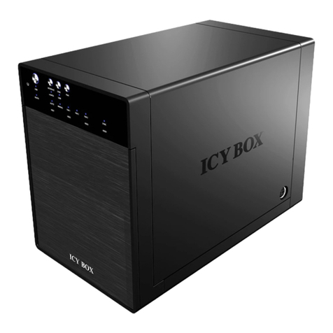
BIOS DVM10U3 User manual

DVM10U3
DVM10U3
Best Energy and Space Saving RAID System.
Portable RAID6, 2.5” HDD×10 - USB3.1 Type-C
Attention
BIOS AP and its resellers are not liable for any data
or information lost or possible software issue to use
the product. We do not take any responsibility of
damage and/or systemmalfunction due to our
product / storage device failure or for any of the
problems caused as a result It is recommended to
always backup your data.
◆ Introduction
This Quick Installation Guide(QIG) describes the packing content and
installation guide line for DVM10U3.
It also explains the function of each connector, button and RAID mode. It is
served as a quick startup for basic configuration, and the details can be
found on User Manual downloadable from website.
Jan 2016 Printing No:01
Quick Installation Guide
Quick Installation Guide
Warranty Information
Publisher BIOS AP Inc.
6F-6A., No. 5, Sec. 3, New Taipei Blvd., Xinzhuang Dist.,
New Taipei City 242, Taiwan
TEL: +886-2-8522-8393 FAX: +886-2-8522-8323
Email: [email protected] Website: www.biosap.com.tw
Doc:DVM10U3_QIGxx.pdf

USB3.1 Cable
(Accessories )
◆ Packing List
The box should contain the DVM10U3 and below accessories
DVM10U3
Quick Installation Guide
Power cable
◆ Name and Function of each part
1.Front
2.Back
Security Key
①① HDD Module
Hot-swappable drive module from top
Disk 0,1,2,3,4,5,6,7,8,9
② HDD POWER / FAIL LED
HDD Power LED: Blue when ON, and Amber if the drive failed
When 「RAID-x RECOVERING 0%」shown on LCD, the FAIL LED on means
the HDD is under rebuilding.
③ HDD ACCESS LED
Green Flash indicates HDD being accessed.
④ Lock Indicator Film
Orange indicates HDD module was locked,Gray indicates HDD module
was unlocked.
⑤ Security Key Insertion Hold
Turn clockwise to lock the HDD module. Check the lock indicator to
see the status of module.
⑥LCD
Display of DVM10 status or parameter
⑦POWER LED
Blue on when system is powered up
⑧ACCESS LED
Green flash with host access
⑨FAIL LED
Amber on indication of any error status
⑩ MODE Button
3 Type mode function
1 )Parameter Initialization (press upon power on)
2 )Parameter setup.
3 )Stop buzzer alarm(press to turn o buzzer)
⑪ SELECT Button
Parameter setup
③
②④ ⑤
⑥
⑦
⑧
⑪
⑫
⑨
⑩
⑬
⑭
⑫ POWER Switch
Switch system power on/o。
⑬ AC Connector
Connect AC Cable
⑭ FAN
Cooling fan 1(Up), 2
⑮ Type-C Connector Host
USB3.1 connection
⑯
⑰
⑱
Ethernet Speed LED
Green ON at power on
Ethernet Link LED
Amber On/Flash indicates link status
LAN Connector
Connect to Ethernet for web management
Power Cable
( Accessories )
LAN Cable
( option )
◇ Packing List
● DVM10U3 Body
● Power cable
●
USB-C cable 1M
● Security Key
● Quick Installation Guide
⑱
DVM10U3 Body
To start with the initialization, please press and hold
the “Mode” button located near LCD screen on the front
panel and turn on POWER button, until LCD screen
change to NORMAL sign. (It takes about 10 second.) It is to reset and initialize the
RAID system for the rst time use. This is one time operation after recongure of
the storage.
A default RAID 6 mode will be shown on LCD as [RAID 6 NORMAL] under regular
Monitor mode. If you wanted to change default configuration, you should power
cycle the unit into Setup Mode.
Under Setup mode you can change RAID parameters, Ethernet connection,
and rmware upgrade. (Notice: Press MODE button to select the parameter for
change. Parameters will not be updated into system till Save operation is executed.
● Parameter Setup: MODE button + SELECT button + Power On
● Rotate among Parameter items: MODE button
● Parameter change: SELECT button
Save operation: By holding MODE and SELECT button at
the same time , the changed parameters will be saved
to internal non-volatile memory then the change is
eective.
When you successfully change the parameter, you will see
「 POWER DOWN
PLEASE ! 」 Then you can
turn o the system. If you power down before saving to
memory the settings will revert to the way they were upon the last save.
●
Saving the change : MODE + SELECT Button then
● Cancel the change : Power o while doing change
◆ Overview of Setup method
To facilitate easy configuration of DVM10U3, a LCD/Keypad is designed on the
front panel for setup of function menu. The default conguration and parameters are
designed for RAID 6 conguration. To avoid malfunction, parameters and conguration
could not be changed on use.
1.Conguration method - LCD Front Panel
Here describes the general method used to congure the unit.
RAID 6
NORMAL
POWER DOWN
PLEASE !
Every thing you can do via LCD front panel can also be done by management
GUI. The default IP address is 192.168.50.210. Connect ethernet cable and
launch the browser with the IP address. Similar to LCD front panel operation,
if you wanted to reconfigure the unit, you have to power it into Setup mode;
otherwise the GUI will be shown as Monitor mode.
Firmware update is only supported by management GUI.
◆ Installation Guide
● Install and Remove HDD Module
(1)Before you start any operation, please make sure HDDs are installed properly into the
DVM10U3 enclosure
(2)Buzzer alarm will be red and caused error if right number of HDD module was not
installed properly
※ When it is used for the very rst time, please push and hold the “Mode” button
located near LCD screen on the front panel while POWER button is pushed on,
until LCD screen change to NORMAL sign. It is to reset and initialize the RAID system
for the rst time use.
● Remove HDD Module
● Install HDD Module
(1)Insert the key into the lock
hole and turn the key
counterclockwise.
(2)Push the lever ofcanister
(3)Pull out the lever and hold
the canister to remove
HDD module
(1)Insert the HDD module
(2)Push the module into the
enclosure and close the lever
(3)Insert the key and turn it
clockwise to lock the module.
(1)
(2)
(3)
(1)
(2)
(3)
⑮
⑯
⑰
USB-C cable 1M
Note: The illustration below with only six drive canisters is used to
demonstrate installation and removal of drive modules. The actual DVM10U3 body
has ten drive canisters
Power on the RAID system while holding both MODE
and SELECT buttons to enter Setup Mode.
Array
Parameter Setting !
2.Configuration method - Ethernet Management GUI
Popular Enclosure manuals by other brands
Martin Audio
Martin Audio W8LD Specification sheet

FRIEDHELM LOH
FRIEDHELM LOH Rittal AX 1485.744 Assembly instructions
LaCie
LaCie THUNDERBOLT SERIES user manual
StarTech.com
StarTech.com DRW115SAT user guide
IBM
IBM 9306 001 Hardware Maintenance Manual
Channell
Channell Green Hornet G5N installation instructions
