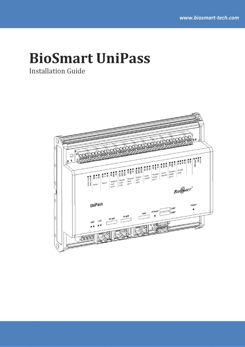
BioSmart UniPass Pro User manual

Version 053.2
Date 08.2021
BioSmart UniPass Pro Controller
Operation Manual

2
BioSmart UniPass Pro Controller
Operation Manual
CONTENTS
1General Information.............................................................................................................................................................................4
2Operation and Design.........................................................................................................................................................................6
2.1 Operating Principle .................................................................................................................................................................6
2.2 Composition.................................................................................................................................................................................6
2.3 Controller Board ........................................................................................................................................................................6
3Operating Limits...................................................................................................................................................................................10
3.1 Mechanical Factors................................................................................................................................................................10
3.2 Climatic Factors .......................................................................................................................................................................10
3.3 Biological Factors....................................................................................................................................................................10
3.4 Electromagnetic Fields and Electric Current .......................................................................................................10
3.5 Additional Restrictions ........................................................................................................................................................10
4Mounting………….. ...................................................................................................................................................................................... 11
4.1 Safety Measures........................................................................................................................................................................ 11
4.2 Mounting Recommendations......................................................................................................................................... 11
4.3 Mounting Procedure ............................................................................................................................................................ 12
4.3.1 Surface Mounting.............................................................................................................................................................. 12
4.3.2 Mounting on DIN-rail ...................................................................................................................................................... 12
5Connection……... ......................................................................................................................................................................................14
5.1 Power Supply Connection ................................................................................................................................................ 14
5.2 Ethernet Network Connection.......................................................................................................................................14
5.3 Connection of BioSmart PalmJet Readers ............................................................................................................ 15
5.4 Connection of Buttons and Passage Sensors ...................................................................................................... 16
5.5 Connection of Electric Locks........................................................................................................................................... 17
5.6 Connection of Discrete Outputs ................................................................................................................................... 19
5.7 Wiegand Connection to a Third-party Controller.............................................................................................20
6Quick Start………. ..................................................................................................................................................................................... 22
6.1 Configuring the Network Parameters ..................................................................................................................... 22
6.2 Adding the Controller to the Biosmart-Studio................................................................................................... 24
6.3 Adding BioSmart Palmet Readers ............................................................................................................................. 28
6.4 Assigning an Access Zone................................................................................................................................................. 31
6.5 Configuring the Controller Working Model ..........................................................................................................32
7Configuration in the Biosmart-Studio....................................................................................................................................35
7.1 Adding the Controller to the Biosmart-Studio....................................................................................................35
7.2 Adding BioSmart Palmet Readers ............................................................................................................................. 38
7.3Assigning an Access Zone................................................................................................................................................ 42
7.4 Controller Properties in the Biosmart-Studio ..................................................................................................... 43
7.4.1 General Information........................................................................................................................................................43

3
BioSmart UniPass Pro Controller
Operation Manual
7.4.2 Control Panel Buttons .................................................................................................................................................. 44
7.4.3 General Tab.......................................................................................................................................................................... 44
7.4.4 System Tab............................................................................................................................................................................45
7.4.5 Diagnostics Tab..................................................................................................................................................................45
7.4.6 Video Cameras Tab..........................................................................................................................................................46
7.4.7 Permissions Tab.................................................................................................................................................................46
8Configuration in the WEB-interface.......................................................................................................................................48
8.1 Access to the WEB-interface..........................................................................................................................................48
8.2 WEB-interface Password and Language...............................................................................................................49
8.3 Configuring the Network Parameters .....................................................................................................................50
8.4 Configuring Operation with the BioSmart PalmJet reader....................................................................... 50
8.5 Polling a Passage Sensor ...................................................................................................................................................53
8.6 Relay Settings............................................................................................................................................................................53
8.7 Discrete Output Settings.................................................................................................................................................. 54
8.8 Button Polling..........................................................................................................................................................................54
8.9 Configuring Data Transmission via Wiegand .....................................................................................................54
8.10 BioSmart Pallet BOX-T Reader Temperature Sensor Settings .................................................................55
8.11 Controller Firmware Update .......................................................................................................................................... 56
9Maintenance…... .................................................................................................................................................................................... 57
10 Storage and Transportation ......................................................................................................................................................... 59
11 Utilization…………...................................................................................................................................................................................... 59

4
BioSmart UniPass Pro Controller
Operation Manual
Please read this operation manual before using the device!
This manual describes the operation, mounting, connection, configuration, operating limits, rules of
storage, transportation and utilization of the BioSmart UniPass Pro controller.
Documentation and software are constantly being improved, the latest up-to-date versions of
documentation and software can be found on the website http://www.biosmart-tech.com/.
Abbreviations used:
ACS –Access Control System;
PC –Personal Computer;
RFID –Radio Frequency Identification;
PoE –Power over Ethernet;
DC –Direct Current;
IP –Internet Protocol.
Important information that should be paid attention to.
1General Information
The BioSmart UniPass Pro controller is designed to organize access control and management, as
well as work time tracking by identifying users by the palm vein pattern and RFID-tags (cards).
The controller is used with BioSmart PalmJet (BioSmart PalmJet BOX, BioSmart PalmJet BOX-T)
biometric readers via the Ethernet interface, as well as with other RFID readers via the Wiegand and
RS-485 (OSDP) interfaces. Buttons, sensors, actuators are connected to the BioSmart UniPass Pro
controller.
Technical Characteristics
Parameter
Value
Processor SoC
Rockchip RK3399
GPU
Mali-T864
RAM memory
4 Gb
Operating system
Linux
Maximum number of users in identification mode (1:N)
100 000
Maximum number of users in verification mode (1:1)
1 000 000
The maximum number of RFID-codes stored on the controller
1 000 000
The maximum number of events stored on the controller
10 000 000
FAR (False Acceptance Rate) *
10-5 –10-8
PC communication interface
Ethernet
(1000BASE-T/100BASE-TX/
10BASE-Te IEEE 802.3)
Maximum number of palm vein readers connected directly to the
controller
2
Maximum number of palm vein readers connected to the
controller using an external switch
4
Number of PoE (IEEE 802.3af class 3)
2
Communication interface with palm vein reader
Ethernet
(100BASE-TX IEEE 802.3u)

5
BioSmart UniPass Pro Controller
Operation Manual
Parameter
Value
Supported interfaces
Wiegand, RS-485 (OSDP),
USB2.0, USB3.0
Supported Wiegand interfaces
26/32/34/37/
40/42/48/64
Number of RS-485 interfaces
2
Number of Wiegand inputs/outputs
2/2
Number of discrete inputs/outputs
6/6
Discrete input voltage, V
from 5 to 12
Discrete output parameters
DC 12 V 50 mA
Discrete output type
Open collector
Number of relays
2
Relay parameters
DC 24 V 7 A
Relay contacts state
Normally open
and normally closed
DC power supply voltage, V
Constant 12 ± 10%
Maximum consumption current, A
4
Case material
Plastic, metal
Dimensions (H x W x D)
180 х 125 х 40
Weight, g
250
Operating temperature range
From -20°C to +50°C
The upper value of the relative air humidity during operation at a
temperature of 25°C
70%
Notes:
*Calculated value depending on controller settings and quality of biometric templates. The False
Rejection Rate (FRR) is less than 3% (with FAR = 10-8).

6
BioSmart UniPass Pro Controller
Operation Manual
2Operation and Design
2.1 Operating Principle
When BioSmart PalmJet readers are connected, the BioSmart UniPass Pro controller, using the
built-in DHCP server, assigns addresses to the readers in the 192.168.103.0 subnet. Interaction between the
controller and readers is carried out via TCP port 20020.
During operation, the controller cyclically polls the status of the connected BioSmart PalmJet
readers. After the controller receives the biometric data (or RFID-tag code) from the reader, the controller
compares it with biometric templates (or codes) stored in the database. If a match is found and access of
the identified user is allowed, the controller performs the actions specified in the controller settings, for
example, activates the relay and sends commands to control the reader indication. If no match is found or
access of the identified employee is denied, the controller performs a different set of actions in accordance
with the settings. Then the controller returns to cyclically polling the status of the readers.
2.2 Composition
BioSmart UniPass Pro controller consists of the following main components:
case with removable front panel;
controller board containing jumpers, connectors and LED indicators.
2.3 Controller Board
This section contains a list and destination of jumpers, connectors and LED indicators, which are
located on the controller board.
Jumpers
Name
Description
TMPR
Jumper to connect a button or an tamper sensor
(buttons, sensors are not included in the delivery set)
IP_RST
Jumper to reset network parameters

7
BioSmart UniPass Pro Controller
Operation Manual
LED Indicators
Name
Indication type and
color
Description
RUN
Flashing green
Normal device operation
ALARM
Red
Receiving an alarm
Relay 1
Green
Relay 1 actuation
Relay 2
Green
Relay 1 actuation
Contacts List
Contact set
Name
Description
Used to connect
GND
GND
Power, common wire
Negative pole of 12 V power supply
+12V
+12V
Power, +12 V
Positive pole of 12 V power supply
Relay 1
C1
Common contact (relay 1)
Actuators
NO1
Normally open contact (relay 1)
NC1
Normally closed contact (relay 1)
Relay 2
C2
Common contact (relay 2)
Actuators
NO2
Normally open contact (relay 2)
NC2
Normally closed contact (relay 2)
Wiegand
input port 0
WI00
Wiegand Input (DATA0)
RFID reader via Wiegand interface
GND
Wiegand ground
WI01
Wiegand Input (DATA1)
Outputs open-
drain
OUT1
Discrete output
Discrete signaling, RFID reader control
OUT2
Discrete output
OUT3
Discrete output
Power out
100mA
+12V
Voltage 12 V
(no more than 100 mA)
Power supply of a third-party low-
power device or connection a button,
sensor
+12V
Voltage 12 V
(no more than 100 mA)
Wiegand
input port 1
WI10
Wiegand input (DATA 0)
RFID reader via Wiegand interface

8
BioSmart UniPass Pro Controller
Operation Manual
Contact set
Name
Description
Used to connect
GND
Wiegand ground
WI11
Wiegand input (DATA 1)
Outputs open-
drain
OUT4
Discrete output
Discrete signaling, RFID reader control
OUT5
Discrete output
OUT6
Discrete output
Inputs
discrete
IN1
Discrete input
Passage sensor, button
IN2
Discrete input
IN3
Discrete input
Wiegand
output port 1
WO10
Wiegand output (DATA0)
Third-party controller via Wiegand
interface
GND
Wiegand ground
WO11
Wiegand output (DATA1)
Power out
20mA
+5V
Voltage 5 V
(no more than 20 mA)
Power supply of a third-party low-
power device or connection of a
button, sensor
+5V
Voltage 5 V
(no more than 20 mA)
Inputs
discrete
IN4
Discrete input
Passage sensor, button
IN5
Discrete input
IN6
Discrete input
Wiegand
output port 0
WO00
Wiegand output (DATA0)
Third-party controller via Wiegand
interface
GND
Wiegand ground
WO01
Wiegand output (DATA1)
RS-485 port 1
GND
RS-485 port 1 ground
RFID readers via the RS-485 (OSDP)
interfaces
B1
Channel B
A1
Channel A
RS-485 port 2
GND
RS-485 port 2 ground
B2
Channel B

9
BioSmart UniPass Pro Controller
Operation Manual
Contact set
Name
Description
Used to connect
A2
Channel A
PV-WM
PV-WM
Ethernet connector
+ PoE IEEE 802.3af class 3
BioSmart PalmJet readers via the
Ethernet interface or via PoE Splitter
PV-WM
Ethernet connector
+ PoE IEEE 802.3af class 3
Host
Host
Ethernet
Ethernet connection
USB
USB 3.0
USB port
Additional equipment
USB 2.0
USB port

10
BioSmart UniPass Pro Controller
Operation Manual
3Operating Limits
This section contains requirements, non-compliance of which is unacceptable for safety reasons and
can lead to the device failure or its performance degradation.
3.1 Mechanical Factors
Do not install the device near sources of vibrations and shock effects. The device can be
installed in places with an insignificant level of shock effects, for example, near closely located
slamming doors;
Avoid mechanical influences that can cause damage to the device case and cause liquid,
dust, insects, foreign objects to get inside the cause;
Do not use abrasive or chemically active materials to clean the outer surfaces of the device.
3.2 Climatic Factors
Do not use the device outside the ambient temperatures and relative humidity values
specified in the technical specifications;
Do not use the device in direct sunlight or close proximity to bright light sources to avoid
overheating the device;
Do not use the device in close proximity to flame sources to avoid overheating and damage
to the device;
Do not use the device when exposed to atmospheric precipitation (hail, rain, snow), as well
as in conditions of frost, freezing and ice, in dusty, smoky, damp, or dirty environments;
Do not use the device in an environment with high concentrations of static or dynamic dust
(sand). Sand particles trapped inside the case or in the connectors of the controller can cause
the device to fail;
Do not use the device in environments with corrosive agents, sea (salt) fog;
3.3 Biological Factors
Do not use the device near mold fungi, insects and animals.
3.4 Electromagnetic Fields and Electric Current
Use the device only at the power supply voltage specified in the technical specifications;
Do not use the device near sources of strong electromagnetic fields to avoid a negative
impact on the operation of electronic components;
Provide lightning protection of the device;
Do not use the device in conditions of ionizing (radiation) exposure.
3.5 Additional Restrictions
Repair or modification of the device by persons not authorized by the manufacturer is
prohibited;
When BioSmart PalmJet readers are connected to the controller via external routers, this
subnet should not contain other DHCP servers, except for the BioSmart UniPass Pro
controller;
When BioSmart PalmJet readers are connected to the controller via a firewall, the
connection and data exchange over the port TCP 20020 must be allowed in the firewall
settings.
The device operation under the influence of factors not listed in this section requires additional
consideration.

11
BioSmart UniPass Pro Controller
Operation Manual
4Mounting
4.1 Safety Measures
Read the following rules before mounting!
Do not mount or start-up the device during a thunderstorm due to the risk of electric shock
during lightning discharges;
Provide lightning protection of the device;
Perform mounting and connection work only with the power supply disconnected;
Check the absence of mechanical damages on the device board and case;
Check the delivery contents.
4.2 Mounting Recommendations
Mount the controller in a convenient for operation place;
Lay cables in compliance with the rules for the electrical equipment operation;
Do not lay cables less than 30 cm away from sources of electromagnetic interference;
Cross all cables with power cables only at right angles;
If necessary, extend the cables by soldering, welding or crimping;
Provide additional length of cables connected to the controller, long enough to move the
controller away from the wall and get access to the jumpers;
Install the appropriate tips on all connected cables.
Used Cable Types
No
Cable connection
Max
length
Type
1
Ethernet –controller
100 m
Four twisted pairs of at least the fifth
category with a wire cross-section of at least
0.2 mm2.
2
Power supply - controller
10 m
Two-core cable with a wire cross-section of
at least 0.75 mm2.
3
Controller –electric lock
20 m
Two-core cable with a wire cross-section of
0.5-1 mm2.
4
Controller - BioSmart PalmJet reader
Ethernet + PoE (power supply from PoE
Splitter installed next to the reader)
100 m
Four twisted pairs of at least the fifth
category with a wire cross-section of at least
0.2 mm2
Controller - BioSmart PalmJet reader
Ethernet only (reader power supply
from a separate source)
100 m
Four or two twisted pairs with a wire cross-
section of at least 0.2 mm2
5
Controller (contacts IN1..IN6, + 5V) -
external devices, buttons, sensors
10 m
Cable with a wire cross-section of 0.2-1 mm2
6
Controller (contacts Wiegand input /
Wiegand output) - external devices.
60 m
Four twisted pairs of at least the fifth
category with a wire cross-section of at least
0.2 mm2.

12
BioSmart UniPass Pro Controller
Operation Manual
4.3 Mounting Procedure
4.3.1 Surface Mounting
To mount on a flat surface, follow the steps:
1. Determine place to install the controller;
2. Insert the supplied flanges into the side slots on the controller case;
3. Mark the attachment points, lay the cables.
4. Fasten the controller case to the mounting surface using the supplied mounting kit.
5. Connect external devices to the controller.
4.3.2 Mounting on DIN-rail
1. Remove one of the side panels from the controller case;

13
BioSmart UniPass Pro Controller
Operation Manual
2. Install the DIN-rail mounting element into the rails on the back of the case;
3. Reattach the side panel;
4. Place the upper clip on the edge of the DIN-rail (1) and press the lower one (2) until it clicks;
5. Connect external devices to the controller.

14
BioSmart UniPass Pro Controller
Operation Manual
5Connection
This section contains the basic connection schemes.
Perform mounting and connection work only with the power supply disconnected!
5.1 Power Supply Connection
The controller is connected to the power supply in accordance with the following scheme.
5.2 Ethernet Network Connection
The controller is connected to the Ethernet network in accordance with the following scheme.
The cable tip is crimped according to the TIA/EIA-568-B standard.

15
BioSmart UniPass Pro Controller
Operation Manual
5.3 Connection of BioSmart PalmJet Readers
The BioSmart PalmJet readers are connected using PoE Splitter in accordance with the following
scheme.
PoE Splitter
BioSmart
PalmJet
Ethernet
PoE Splitter BioSmart
PalmJet
Ethernet
Ethernet
+ PoE
Ethernet
+ PoE
12 V
12 V

16
BioSmart UniPass Pro Controller
Operation Manual
The BioSmart PalmJet readers are connected using a separate power supply in accordance with the
following scheme.
BioSmart
PalmJet
BioSmart
PalmJet
+
Ethernet
Ethernet
Power Supply
-
The BioSmart PalmJet BOX and BioSmart PalmJet BOX-T readers are connected similarly.
5.4 Connection of Buttons and Passage Sensors
Buttons and passage sensors are connected to the IN1 ... IN6 discrete inputs and the +12V or +5V
power outputs. An example of connecting a button/passage sensor is shown in the scheme.
12 V

17
BioSmart UniPass Pro Controller
Operation Manual
Button
Passage
sensor
5.5 Connection of Electric Locks
Install a shunt diode in accordance with the schemes below to protect the relay from
the reverse current that occurs in the circuit when the lock is triggered. It is
recommended to use a 1N4007diode (included in the delivery package) or equivalent.
Electric locks must be powered from an external voltage source.
Do not use the same power supply for the lock and controller!
An electromagnetic lock is connected to the C1 (C2) and NC1 (NC2) contacts of relay 1 (relay 2),
according to the scheme.

18
BioSmart UniPass Pro Controller
Operation Manual
Power supplyElectromagnetic lock
VD1
GND
GND ++
An electromechanical lock is connected to the C1 (C2) and NO1 (NO2) contacts of relay 1 (relay 2),
according to the scheme.
Power supplyElectromechanical lock
VD1
GND
GND +
+

19
BioSmart UniPass Pro Controller
Operation Manual
5.6 Connection of Discrete Outputs
The discrete outputs OUT 1… OUT 6 are used to switch the voltage on an external load.
The load may be connected to the same power supply as the controller, or to a separate source.
When the load is connected to a separate power supply, the GND contacts of the load power supply and
GND contacts of the controller power supply are connected.
The current flowing through the discrete output must not exceed 50 mA, the voltage
must not exceed 12 V. At a voltage of 12 V, the load resistance must be at least
250 ohms. If the load resistance is insufficient, use the pull-up resistor supplied with
the controller (300 Ohm, 0.5 W) or equivalent that provides a maximum current in the
circuit of no more than 50 mA.
An example of connecting the load to the discrete output of the controller when using a common
power source for the load and the controller is shown in the scheme below. It does not matter which
particular discrete output (OUT 1 ... OUT 6) the load is connected to. The resistor (R) is used to limit the
current at the discrete output.
External load
GND +
Power supply
12 V
R
An example of connecting the load to the discrete output of the controller when using separate
power supply for the load is shown in the scheme below. It does not matter which particular discrete output
(OUT 1 ... OUT 6) the load is connected to and which particular GND contact the load power supply is
connected to. The resistor (R) is used to limit the current at the discrete output.

20
BioSmart UniPass Pro Controller
Operation Manual
External load
GND +
Power supply
12 V
R
Power
supply for
the load
+GND
5.7 Wiegand Connection to a Third-party Controller
The controller is connected to a third-party controller via the Wiegand interface using WO00, WO01
and GND contacts of the first communication line or WO10, WO11 and GND contacts of the second
communication line. An example of connecting to a third-party controller is shown in the following scheme.
Table of contents
Other BioSmart Controllers manuals
Popular Controllers manuals by other brands

Vacon
Vacon 20 x Installation, Technical and Maintenance Manual
ETC
ETC Element user manual
National Instruments
National Instruments sbRIO-9628 Quick reference guide

Pyrotronix
Pyrotronix ptx Mini manual
Adaptec
Adaptec 2120S - SCSI RAID Controller Software reference guide
Winext
Winext WLC-NEMA-01 user manual
Emerson
Emerson E2 Installation and operation manual

KE2 Therm Solutions
KE2 Therm Solutions Evaporator Efficiency installation instructions

Grundfos
Grundfos EZ Boost Installation and operating instructions
Plejd
Plejd CTR-01 instruction manual

Isimet
Isimet LA Checklist
Nordic
Nordic Deltaco SH-OW01 user manual
