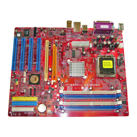
Biostar P31B-A7 - BIOS User manual

P31B-A7 BIOS Manual
i
BIOS Setup.................................................................................................1
1Main Menu...............................................................................................3
2Advanced Menu.......................................................................................7
3PCIPnP Menu........................................................................................18
4Boot Menu..............................................................................................22
5Chipset Menu.........................................................................................24
6Performance Menu...............................................................................28
7Exit Menu...............................................................................................30

P31B-A7 BIOS Manual
1
BIOS Setup
Introduction
The purpose of this manual is to describe the settings in the AMI BIOS Setup
program on this motherboard. The Setup program allows users to modify the basic
system configuration and save these settings to CMOS RAM. The power ofCMOS
RAM is supplied by abattery so that it retains theSetup information when the power
is turned off.
Basic Input-Output System (BIOS) determines what a computer can do without
accessing programs from a disk. This system controls most of the input and output
devices such as keyboard, mouse, serial ports and disk drives. BIOS activates at the
first stage ofthe booting process, loading and executing the operating system. Some
additional features, such as virus and password protection or chipset fine-tuning
options are also included in BIOS.
The rest of this manual will to guide you through the options and settings in BIOS
Setup.
Plugand Play Support
ThisAMI BIOS supports thePlug and Play Version 1.0A specification.
EPA Green PC Support
ThisAMI BIOS supports Version 1.03 ofthe EPA Green PC specification.
APM Support
This AMI BIOS supports Version 1.1&1.2 of the Advanced Power Management
(APM) speci fication. Power management features are implemented via the System
Management Interrupt (SMI). Sleep and Suspend power management modes are
supported. Power to the hard disk drives and video monitors can also be managed by
this AMI BIOS.
ACPI Support
AMI ACPI BIOS support Version 1.0/2.0 of Advanced Configuration and Power
interface specification (ACPI). It provides ASL code for power management and
device configuration capabilities as defined in theACPI specification, developed by
Microsoft, Intel and Toshiba.

P31B-A7 BIOS Manual
2
PCI Bus Support
This AMI BIOS also supports Version 2.3 of the Intel PCI (Peripheral Component
Interconnect) local bus specification.
DRAM Support
DDR2 SDRAM (Double Data Rate II Synchronous DRAM) is supported.
Supported CPUs
ThisAMI BIOS supports the Intel CPU.
Using Setup
When starting up the computer, press
<Del> during the Power-On Self-Test
(POST) to enter theBIOS setup utility.
In the BIOS setup utility, you will see
General Help description at the top right
corner, and this is providing a brief
description of the selected item.
Navigation Keys for that particular menu
are at the bottom right corner, and you can
use these keys to select item and change
the settings.
Notice
zThe default BIOS settings apply for most conditions to ensure optimum performance
of the motherboard. If the system becomes unstable after changing any settings,
please load the default settings to ensure system’s compatibility and stability. Use
Load Setup Default under the Exit Menu.
zFor better system performance, the BIOS firmware is being continuously updated.
The BIOS information described in this manual isfor yourreferenceonly. The actual
BIOS information and settings on board may be slightly different from this manual.
zThe content ofthis manual is subject to be changed without notice. We will not be
responsible for any mistakes found in this user’s manual and any system damage that
may be caused by wrong-settings.
General Help
Navigation Keys

P31B-A7 BIOS Manual
3
1 Main Menu
Once you enter AMI BIOS Setup Utility, the Main Menu will appear on the screen
providing an overviewof the basic system information.
BIOS SETUP UTILITY
Main Advanced PCIPnP Boot Chipset Performance
vxx.xx (C)Copyright 1985-200x, American Megatrends, Inc.
Select Screen
Select Item
Change Field
Select Field
General Help
Save and Exit
Exit
+-
Tab
F1
F10
ESC
Use [ENTER], [TAB]
or [SHIFT-TAB] to
select a field.
Use [+] or [-] to
configure system Time.
System Overview
AMI BIOS
System Memory
[ :00:00]
System Date [Tue 01/01/2008]
Floppy A
> IDE Configuration
Version :01.01.01
Build Date:01/01/08
Size :
System Time 00
Exit
AMI BIOS
Shows systeminformation including BIOS version, built date, etc.
System Memory
Shows systemmemory size, VGA shard memory will be excluded..
System Time
Set the systeminternal clock.
System Date
Set the system date. Note that the ‘Day’ automatically changes when you set the
date.

P31B-A7 BIOS Manual
4
Floppy A
Select the typeof floppy disk drive installed in yoursystem.
Options: 360K, 5.25in / 1.2M, 5.25 in/ 720K, 3.5 in / 1.44M, 3.5 in /
2.88M, 3.5in / None
IDE Configuration
The BIOS will automatically detect the presence of IDE/SATA devices. There is a
sub-menu for each IDE/SATA device. Select a device and press <Enter> to enter
the sub-menu ofdetailed options.
BIOS SETUP UTILITY
Main
vxx.xx (C)Copyright 1985-200x, American Megatrends, Inc.
Select Screen
Select Item
Go to Sub Screen
General Help
Save and Exit
Exit
Enter
F1
F10
ESC
IDE Confuguration
Configure SATA Channels [Before PATA]
Legacy IDE Channels [SATA Pri, PATA Sec]
> SATA1 DEVICE
>
>
Hard Disk Write Pr otect [Disabled]
IDE Detect Time Out (Sec) [35]
SATA2 DEVICE
SATA3 DEVICE
> SATA4 DEVICE
> IDE Channel 1 Ma ster
> IDE Channel 1 Sl ave
ATA/IDE Configuration [Enhanced]
Options
Disabled
Compatible
Enhanced
ATA/IDE Configuration
Thisitem allows you to control theonboard IDE controller.
Options: Enhanced (Default) / Compatible/ Disabled
Configure SATA Channels
Thisitem allows you to control theSATA channel configuration sequence.
Options: Before PATA (Default) / Behind PATA
Legacy IDE Channels
Thisitem appears only when “ATA/IDE Configuration” is set to“Compatible”.
Options: SATA Pri, PATA Sec (Default) / SATA Only/ PATAPri, SATA Sec /
PATA Only

P31B-A7 BIOS Manual
5
SATA1/2/3/4 Device; IDE Channel 1Master/Slave
BIOS SETUP UTILITY
Main
vxx.xx (C)Copyright 1985-200x, American Megatrends, Inc.
Select Screen
Select Item
Change Option
General Help
Save and Exit
Exit
+-
F1
F10
ESC
SATA1 Device
LBA/Large Mode [Auto]
Block (Multi-Secto r Transfer)[ Auto]
PIO Mode [Auto]
DMA Mode [Auto]
S.M.A.R.T [Auto]
32Bit Data Transfe r [Enabled]
Device :
Type [Auto]
Options
Not Installed
Auto
CD/DVD
ARMD
The BIOS detects the information and values of respective devices, and these
information and values are shown below to the name of thesub-menu.
Type
Select the typeofthe IDE/SATAdrive.
Options: Auto (Default) / CD/DVD / ARMD / Not Installed
LBA/Large Mode
Enable or disable the LBA mode.
Options: Auto (Default) / Disabled
Block (Multi-Sector Transfer)
Enable or disable multi-sector transfer.
Options: Auto (Default) / Disabled
PIOMode
Select the PIO mode.
Options: Auto (Default) / 0 / 1/ 2 / 3 /4
DMA Mode
Select the DMA mode.
Options: Auto (Default) / Disabled

P31B-A7 BIOS Manual
6
S.M.A.R.T
Set the Smart Monitoring, Analysis, andReportingTechnology.
Options: Auto (Default) / Disabled / Enabled
32Bit Data Transfer
Enable or disable 32-bit data transfer.
Options: Enabled (Default) / Disabled
Hard Disk Write Protect
Disable or enable device write protection. Thiswill be effective only if the device
is accessed through BIOS.
Options: Disabled (Default) / Enabled
IDE Detect Time Out (Sec)
Select the time out value for detecting IDE/SATA devices.
Options: 35 (Default)/ 30 / 25/ 20 / 15 / 10 / 5 / 0

P31B-A7 BIOS Manual
7
2Advanced Menu
The Advanced Menu allows you to configure thesettings of CPU, Super I/O, Power
Management, and other system devices.
Notice
zBeware of that setting inappropriate values in items of this menu may cause
system tomalfunction.
BIOS SETUP UTILITY
Main Advanced PCIPnP Boot Chipset Performance
vxx.xx (C)Copyright 1985-200x, American Megatrends, Inc.
Select Screen
Select Item
Go to Sub Screen
General Help
Save and Exit
Exit
Enter
F1
F10
ESC
Configure CPU.Advanced Settings
WARNING: Setting wrong values in below sections
may cause system to malfunction.
> USB Configuration
> SuperIO Configuration
> Hardware Health Configuration
> Smart Fan Configuration
> Power Configuration
> CPU Configuration
Exit
CPU Configuration
Thisitem shows theCPU information that theBIOS automatically detects.
BIOS SETUP UTILITY
Advanced
vxx.xx (C)Copyright 1985-200x, American Megatrends, Inc.
Select Screen
Select Item
Change Option
General Help
Save and Exit
Exit
+-
F1
F10
ESC
Configure advanced CPU settings
Module Version:xx.xx
Manufacturer:Intel
Frequency :
FSB Speed :
Cache L1 :
Cache L2 :
Ratio Status:
Ratio Actual Value:
C1E Support [Enabled]
Max CPUID Value Limit [Disabled]
Execute-Disable Bit Capability [Enabled]
PECI [Disabled]
Core Multi-Processing [Enabled]
Intel(R) SpeedStep(tm) tech [Enabled]
Options
Disabled
Enabled

P31B-A7 BIOS Manual
8
C1E Support
C1E is “Enhanced Halt State” function, this function helps to save power and
decrease heat by lowering CPUfrequency while the processor is not working.
Options: Enabled (Default) / Disabled
Max CPUID Value Limit
When the computer is booted up, the operating system executes the CPUID
instruction to identify the processor and its capabilities. Before it can do so, it must
first query the processor to find out the highest input value CPUID recognizes. This
determines thekind ofbasic information CPUID can provide the operating system.
Options: Disabled (Default) / Enabled
Execute-Disable Bit Capability
Thisitem allows you to configure the Execute Disabled Bit function, which protects
yoursystem from buffer overflow attacks.
Options: Enabled (Default) / Disabled
PECI
This item allows you to control the PECI function for the processor which supports
Platform Environment Control Interface for betterthermal management.
Options: Disabled (Default) / Enabled
Core Multi-Processing
Thisitem allows multi-processing function for multi-core processors.
Options: Enabled (Default) / Disabled
Intel(R) SpeedStep(tm) Tech
This item allows you to enable SpeedStep technology for better power saving.
SpeedStep is a technology built into some Intel processors that allows the clock
speed of the processor to be dynamically changed by software.
Options: Enabled (Default) / Disabled

P31B-A7 BIOS Manual
9
SuperIO Configuration
BIOS SETUP U TILITY
Advanced
vxx.xx (C)Copyright 1985-200x, American Me gatrends, Inc.
Select Screen
Select Item
Change Option
General Help
Save and Exit
Exit
+-
F1
F10
ESC
Allows BIOS to Enable
or Disable Floppy
Controller
Configure ITE8712 Super IO Chipset
Onboard Floppy Controller [Enabled]
Serial Port1 A ddress [3F8/IRQ4]
Parallel Port Address [378]
Parallel Por t Mode [Normal]
Parallel Por t IRQ [IRQ 7]
Keyboard PowerOn [Disabled]
Mouse PowerOn [Disabled]
Restore on AC Power Loss [Power Off]
Onboard Floppy Controller
Select enabled if your system has a floppy disk controller (FDC) installed on the
system board and you wish to use it. Ifyou installed another FDC or the system uses
no floppy drive, select disabledin this field.
Options: Enabled (Default) / Disabled
Serial Port1Address
Select an address and corresponding interrupt for the first and second serial ports.
Options: 3F8/IRQ4 (Default) / 2F8/IRQ3 / 3E8/IRQ4 / 2E8/IRQ3/ Auto / Disabled
ParallelPort Address
Thisitem allows you to determine access onboard parallel port controller with which
I/O Address.
Options: 378 (Default) / 278 / 3BC / Disabled
ParallelPortMode
Thisitem allows you to determine how the parallel port should function.
Options: Normal (Default) Using Parallel port as Standard Printer Port.
EPP Using Parallel Port as Enhanced Parallel Port.
ECP Using Parallel port as Extended Capabilities Port.
ECP+EPP Using Parallel port as ECP& EPP mode.

P31B-A7 BIOS Manual
10
ECP Mode DMA Channel
Thisitem allows you to select parallel port ECP DMA.
Options: DMA3 (Default) / DMA0 / DMA1
Parallel Port IRQ
Thisitem allows you to select the IRQ for the onboard parallel port.
Options: IRQ7 (Default) / IRQ5 / Disabled
Keyboard PowerOn
Thisitem allows you to control thekeyboard power on function.
Options: Disabled (Default) / Specific Key / Stroke Key
Specific KeyEnter
Thisitem will show only when Keyboard PowerOn is set “Specific Key.”
Stroke KeysSelected
Thisitem will show only when Keyboard PowerOn is set “Stroke Key.”
Options: Ctrl+F1 (Default) / Wake Key / Power Key / Ctrl+F2 / Ctrl+F3 /
Ctrl +F4 / Ctrl+F5 / Ctrl+F6
MousePowerOn
Thisitem allows you to control themouse power on function.
Options: Disabled (Default) / Enabled
Restore on AC Power Loss
Thissetting specifies how your system should behave aftera power fail or interrupts
occurs. By choosing Disabled will leave the computer in the power off state.
Choosing Enabled will restore the system to the status before power failure or
interrupt occurs.
Options: Power Off(Default)/ Power ON / LastState

P31B-A7 BIOS Manual
11
Hardware HealthConfiguration
Thisitem shows the system temperature, fan speed, and voltage information.
Advanced
Hardware Health Configuration
H/W Health Function [Enabled]
Shutdown Temperature Function[ Disabled]
CPU Temperature
CPU FAN Speed
SYS FAN Speed
CPU Vcore
Chipset Voltage
+3.30V
+5.00V
+12.0V
FSB Voltage
Memory Voltage
5V(SB)
BIOS SETUP UTILITY
vxx.xx (C)Copyright 1985-200x, Amer ican Megatrends, Inc.
Select Screen
Select Item
Change Option
General Help
Save and Exit
Exit
+-
F1
F10
ESC
Options
Disabled
Enabled
H/W Health Function
If with a monitoring system, the system will show PC health status during POST
stage.
Options: Enabled (Default) / Disabled
Shutdown Temperature Function
This item allows you to set up the CPU shutdown Temperature. This item is only
effective under Windows 98 ACPI mode.
Options: Disabled (Default) / 60℃/140℉/ 65℃/149℉/ 70℃/158℉/ 75℃/167℉
/ 80℃/176℉/ 85℃/185℉/ 90℃/194℉

P31B-A7 BIOS Manual
12
Smart Fan Configuration
BIOS SETUP UTILITY
Advanced
vxx.xx (C)Copyright 1985-200x, Amer ican Megatrends, Inc.
Select Screen
Select Item
Change Option
General Help
Save and Exit
Exit
+-
F1
F10
ESC
Smart Fan Configur ation
CPU Smart Fan [Disabled]
Smart Fan Calibrat ion
Control Mode
Fan Ctrl OFF( C)
o
Fan Ctrl On( C)
Fan Ctrl Start value
Fan Ctrl Sensitive
o
Options
Disabled
Auto
CPU SmartFan
Thisitem allows you to control theCPUSmart Fan function.
Options: Disabled (Default) / Auto
Smart Fan Calibration
Choose this item and then the BIOS will auto test and detect the CPU/System fan
functions and show CPU/Systemfan speed.
Control Mode
Thisitem provides several operation modes ofthefan.
Options: Quiet / Performance/ Manual
Fan Ctrl OFF(℃ )
IftheCPU/System Temperatureis lowerthan theset value, FAN will turn off.
Options: 0~127 (℃)(With the interval of1℃)
Fan Ctrl On(℃ )
CPU/System fan starts to work under smart fan function when arrivethis set value.
Options: 0~127 (℃)(With the interval of1℃)

P31B-A7 BIOS Manual
13
Fan Ctrl Start Value
When CPU/System temperature arrives to the set value, the CPU/System fan will
work under Smart Fan Functionmode.
Options: 0~127 (With theinterval of 1)
Fan Ctrl Sensitive
Increasing the value will raise the speed of CPU/System fan.
Options: 1~127 (With theinterval of 1)
Power Configuration
BIOS SETUP UTILITY
Advanced
vxx.xx (C)Copyright 1985-200x, American Megatrends, Inc.
Select Screen
Select Item
Change Option
General Help
Save and Exit
Exit
+-
F1
F10
ESC
ACPI Settings
Advanced Resume Event Controls
Suspend mode [S1(POS)]
ACPI Version Features [ACPI v1.0]
ACPI APIC support [Enabled]
AMI OEMB table [Enabled]
Headless mode [Disabled]
Energy Lake Feature [Disabled]
APIC ACPI SCI IRQ [Disabled]
USB Device Wakeup From S3/S4 [Disabled]
High Performance Event Timer [Disabled]
Res ume On PME# [Disabled]
Res ume On RTC Alarm [Disabled]
RTC Alarm Date(Days)
Time
Resume On Ring [Disabled]
RTC Alarm
Options
S1 (POS)
S3 (STR)
Auto
Suspend mode
The item allows you to select the suspend type under the ACPIoperating system.
Options: S1 (POS) (Default) Power on Suspend
S3(STR) Suspend toRAM
Auto POS+STR
Repost Video on S3 Resume
The item allows you to determine whether to invoke VGA BIOS post on S3/STR
resume.
Options: No (Default) / Yes

P31B-A7 BIOS Manual
14
ACPI Version Features
The item allows you to select the version of ACPI.
Options: ACPI v1.0 (Default)/ ACPI v2.0 / ACPI v3.0
ACPI APIC support
This item is used to enable or disable the motherboard's APIC (Advanced
Programmable Interrupt Controller). The APIC provides multiprocessor support,
moreIRQs and faster interrupt handling.
Options: Enabled (Default) / Disabled
AMI OEMB table
Set this valueto allowthe ACPIBIOS toadd a pointer to an OEMBtable intheRoot
System Description Table (RSDT) table.
Options: Enabled (Default) / Disabled
Headless mode
This is a server-specific feature. A headless server is one that operates without a
keyboard, monitor or mouse. To run in headless mode, both BIOS and operating
system (e.g. WindowsServer 2003) must supportheadless operation.
Options: Disabled (Default) / Enabled
Energy Lake Feature
Thisitem allows you control theenergy lake feature.
Options: Disabled (Default) / Enabled
APICACPI SCI IRQ
Options: Disabled (Default) / Enabled
USBDevice Wakeup from S3/S4
Thisitem allows you to enable or disabled the USB resumefrom S3/S4 function.
Options: Disabled (Default) / Enabled

P31B-A7 BIOS Manual
15
High Performance Event Timer
Thisitem allows you to enable or disabled the HPET.
Options: Disabled (Default) / Enabled
HPETMemory Address
Thisitem allows you to set the memory address ofHPET.
Options: FED00000h (Default) / FED01000h / FED02000h / FED03000h
Resume OnRing
Thisitem allows you control thewake onring function.
Options: Disabled (Default) / Enabled
Resume OnPME#
When you select Enabled, a PME signalfrom PCIcard returns the system toFull ON
state.
For this function to work, you may need a LAN add-on card which supports the
Wake on LAN function. Set the Wake on LAN (WOL) jumper on motherboard to
enable if applicable.
Options: Disabled (Default) / Enabled
Resume On RTC Alarm
When “Enabled”, you can set the date and time at which the RTC (real-time clock)
alarm awakens the system from Suspend mode.
Options: Disabled (Default) / Enabled
RTC Alarm Date (Days)
You can choose which date the system will boot up.
RTC Alarm Time
You can choose the system boot up time, input hour, minute and second to specify.

P31B-A7 BIOS Manual
16
USB Configuration
Thisitem shows the USB controller and using USB deviceinformation.
BIOS SETUP UTILITY
Advanced
vxx.xx (C)Copyright 1985-200x, American Megatrends, Inc.
Select Screen
Select Item
Change Option
General Help
Save and Exit
Exit
+-
F1
F10
ESC
USB Configuration
USB Devices Enabled:
Module Version - 2.24.3-13.4
Legacy USB Support [Enabled]
USB 2.0 Controller Mode [HiSpeed]
BIOS EHCI Hand-Off [Enabled]
> USB Mass Storage Device Conf iguration
Options
Disabled
Enabled
Auto
Legacy USB Support
This item determines if the BIOS should provide legacy support for USB devices
like the keyboard, mouse, and USB drive. This is a useful feature when using such
USB devices with operating systems that do not natively support USB (e.g.
Microsoft DOS or Windows NT).
Options: Enabled (Default) / Disabled / Auto
USB2.0 ControllerMode
Thisitem allows you to select the operation modeof the USB 2.0 controller.
Options: HiSpeed (Default) USB 2.0-480Mbps
FullSpeed USB 1.1-12Mbps
BIOS EHCI Hand-Off
This item allows you to enable support for operating systems without an EHCI
hand-off feature.
Options: Enabled (Default) / Disabled

P31B-A7 BIOS Manual
17
USBMass Storage Device Configuration
BIOS SETUP UTILITY
Advanced
vxx.xx (C)Copyright 1985-200x, American Megatrends, Inc.
Select Screen
Select Item
Change Option
General Help
Save and Exit
Exit
+-
F1
F10
ESC
Number of seconds
POST waits for the
USB mass storage
device after start
unit command.
USB Mass Storage Device Configuration
USB Mass Storage Reset Delay [20 Sec]
Emulation Type [Auto]
Device #
USB Mass Storage Reset Delay
Thisitem allows you to set the reset delay for USB mass storage device.
Options: 20 Sec (Default) / 10 Sec / 30Sec / 40Sec
Emulation Type
Thisitem allows you to select the emulation typeof the USB mass storage device.
Options: Auto (Default) / Floppy / Forced FDD / Hard Disk / CDROM

P31B-A7 BIOS Manual
18
3 PCIPnP Menu
This section describes configuring the PCI bus system. PCI, or Personal Computer
Interconnect, is a system which allows I/O devices to operate at speeds nearing the
speed ofthe CPU itselfuses when communicatingwith itsown special components.
Notice
zBeware of that setting inappropriate values in items of this menu may cause
system tomalfunction.
BIOS SETUP UTILITY
Main Advanced PCIPnP Boot Chipset
Performance
vxx.xx (C)Copyright 1985-200x, American Megatrends, Inc.
Select Screen
Select Item
Change Option
General Help
Save and Exit
Exit
+-
F1
F10
ESC
Clear NVRAM during
System Boot.
Advanced PCI/PnP Settings
WARNING: Setting wrong values in below sections
may cause system to malfunction.
Plug & Play O/S [No]
PCI Latency Timer [64]
Allocate IRQ to PCI VGA [Yes]
Palette Snooping [Disabled]
PCI IDE BusMaster [Enabled]
> PCI Resource
> PCI Express Configuration
Clear NVRAM [No]
Exit
Clear NVRAM
Thisitem allows you to clear thedata in the NVRAM (CMOS) by selecting “Yes”.
Options: No (Default) / Yes
Plug & Play OS
When set to YES, BIOS will only initialize the PnP cards used for the boot sequence
(VGA, IDE, SCSI). The rest of the cards will be initialized by the PnP operating
system like Window™ 95. When set to NO, BIOS will initialize all the PnP cards.
For non-PnP operating systems (DOS, Netware™), this option must set to NO.
Options: No (Default) / Yes

P31B-A7 BIOS Manual
19
PCI Latency Timer
Thisitem controls how long a PCI device can hold the PCI bus before another takes
over. The longer the latency, the longer the PCI device can retain control ofthe bus
before handing it overto another PCI device.
Options: 64 (Default) / 32 / 96/ 128 / 160 / 192/ 224 / 248
Allocate IRQ to PCI VGA
Thisitem allows BIOSto choose a IRQ to assignfor the PCI VGA card.
Options: Yes (Default) / No
Palette Snooping
Someold graphic controllers need to “snoop” on the VGApalette and then map it to
their display as a way to provideboot information and VGA compatibility. This item
allows such snooping to take place.
Options: Disabled (Default) / Enabled
PCI IDE BusMaster
Thisitem is atoggle for the built-in driver that allows theonboard IDE controller to
perform DMA (Direct Memory Access) transfers.
Options: Enabled (Default) / Disabled
PCI Resource
BIOS SETUP UTILITY
PCIPnP
vxx.xx (C)Copyright 1985-200x, American Megatrends, Inc.
Select Screen
Select Item
Change Option
General Help
Save and Exit
Exit
+-
F1
F10
ESC
PCI Resource
IRQ3 [Available]
IRQ4 [Available]
IRQ5 [Available]
IRQ7 [Available]
IRQ9 [Available]
IRQ10 [Available]
IRQ11 [Available]
IRQ14 [Available]
IRQ15 [Available]
DMA Channel 0 [Available]
DMA Channel 1 [Available]
DMA Channel 3 [Available]
DMA Channel 5 [Available]
DMA Channel 6 [Available]
DMA Channel 7 [Available]
Reserved Memory Size [Disabled]
Options
Available
Reserved
Table of contents
Other Biostar Motherboard manuals

Biostar
Biostar BIELK-PAT User manual

Biostar
Biostar TH55 HD - BIOS User manual

Biostar
Biostar A770E3 User guide

Biostar
Biostar TA75M User guide

Biostar
Biostar Z590I VALKYRIE User manual

Biostar
Biostar M6TSS User manual

Biostar
Biostar H310MHD PRO2 User manual

Biostar
Biostar G41D3+ User manual

Biostar
Biostar A780L3L User guide

Biostar
Biostar G31E-M7 - BIOS User manual

Biostar
Biostar A58MD User guide

Biostar
Biostar M6VSB User manual

Biostar
Biostar Hi-Fi A70U3 User guide

Biostar
Biostar M6TLI Manual

Biostar
Biostar X370GT3 User manual

Biostar
Biostar B460GTQ User manual

Biostar
Biostar Z790 VALKYRIE User manual

Biostar
Biostar G41D3 User manual

Biostar
Biostar K8NHA-M Grand User manual

Biostar
Biostar TG31-A7 Manual