9
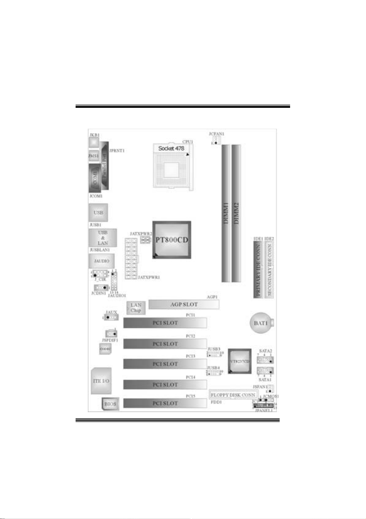
6. Jumpers, Headers, Connectors &Slots
(1)FloppyDiskConnector: FDD1
The motherboard provides a standardfloppy disk connector that supports 360K,
720K, 1.2M, 1.44M and 2.88M floppy disk types. This connector supports the
providedfloppy drive ribbon cables.
(2)Hard Disk Connectors: IDE1/ IDE2
The motherboard has a 32-bit Enhanced PCI IDE Controller that provides PIO
Mode 0~4, Bus Master, and Ultra DMA 33/ 66/ 100/ 133 functionality. It has two
HDD connectors IDE1 (primary) and IDE2 (secondary).
The IDE connectorscan connect a master and a slave drive, soyou canconnect
up to four hard disk drives. The first hard drive should always be connected to
IDE1.
(3) Peripheral Component Interconnect Slots: PCI 1-5
This motherboard isequipped with 5 standard PCI slots.PCI standsfor Peripheral
Component Interconnect, and it is a bus standard for expansion cards. This PCI
slot is designated as32 bits.
(4) Accelerated Graphics Port Slot: AGP1
Your monitor will attach directly to that video card. This motherboard supports
video cardsfor PCIslots, but it is also equippedwith anAccelerated Graphics Port
(AGP). An AGP card will take advantage of AGP technology for improved video
efficiency and performance, especially with 3D graphics.
(5)Communication Network RiserSlot:CNR1 (does not
support on version 7.x)
The CNR specification is anopen Industry Standard Architecture, and it defines a
hardware scalable riser card interface,which supports modem only.
(6)Serial ATA Connector:SATA1/ SATA2
The motherboard has a PCI to SATA Controller with 2 channels SATA interface, it
satisfies the SATA 1.0 spec and can transfer data with 1.5GHzspeed.
Pin Assignment Pin Assignment
1 Ground 2 TX+
3 TX- 4 Ground
5 RX- 6 RX+
1
23
4
56
7
SATA1/ SATA2 7 Ground