Biral VPF Series User manual

VPF Series
Present Weather Sensors
VPF-710
VPF-730
VPF-750
i
PROPRIETARY NOTICE
The information contained in this manual (including all illustrations, drawings, schematics and parts lists) is
proprietary to BIRAL. It is provided for the sole purpose of aiding the buyer or user in operating and maintaining
the instrument. This information is not to be used for the manufacture or sale of similar items without written
permission.
COPYRIGHT NOTICE
No part of this manual may be reproduced without the express permission of BIRAL
© 2017 Bristol Industrial and Research Associates Limited (BIRAL)
Manual Number: 102186
Revision: 07B
Biral –P O Box 2, Portishead, Bristol BS20 7JB, UK
Tel: +44 (0)1275 847787
Fax:+44 (0)1275 847303
Email: enquiries@biral.com
www.biral.com

ii
CONTENTS
GENERAL INFORMATION
Manual version............................................................................................. i
Contents ................................................................................................... ii
Figures.......................................................................................................iii
Tables........................................................................................................iii
The sensors covered in this manual .............................................................. v
Features of the HSS sensors ....................................................................... vi
Customer satisfaction and After Sales Support.............................................viii
Contacting Biral.........................................................................................viii
Five year warranty ..................................................................................... ix
If you need to return the sensor.................................................................. ix
CE Certification –Safety ............................................................................. x
1SENSOR SET-UP.......................................................................................................... 1
1.1 STEP 1 - Unpacking the sensor........................................................................... 2
1.2 STEP 2 - Electrical Connections......................................................................... 4
1.3 STEP 3 - Equipment Test.................................................................................... 8
1.4 STEP 4 - Configuration Options ....................................................................... 10
1.5 STEP 5 - Installation ......................................................................................... 22
1.6 STEP 6 - Test and Commissioning.................................................................... 30
2STANDARD OPERATING DATA............................................................................ 36
2.1 Data Output Message VPF-710......................................................................... 37
2.2 Data Output Message VPF-730......................................................................... 41
2.3 Data Message Variations For ALS or WSM (VPF-710 and VPF-730) ............ 46
2.4 Data Output Message VPF-750......................................................................... 47
3COMMANDS AND RESPONSES ............................................................................ 58
3.1 Sensor Commands............................................................................................. 58
3.2 Sensor Responses .............................................................................................. 65
4MAINTENANCE PROCEDURES............................................................................. 66
4.1 General Checks.................................................................................................. 66
4.2 Self-Test Codes ................................................................................................. 68
4.3 User Confidence Checks ................................................................................... 71
5CALIBRATION PROCEDURES............................................................................... 75
5.1 Calibration Plaque Identification....................................................................... 75
5.2 Calibration Check.............................................................................................. 77
5.3 Sensor Re-Calibration........................................................................................ 80
5.4 Temperature Calibration (Not VPF-750)........................................................... 82
5.5 Precipitation Amount Calibration...................................................................... 82
6MEASUREMENT PRINCIPLES............................................................................... 84
6.1 Visibility Measurement Terminology................................................................ 84
6.2 Visual Range Determination ............................................................................. 84
6.3 Extinction Coefficient Calibration..................................................................... 87
6.4 Theory of Forward Scatter Meters..................................................................... 88
6.5 Precipitation Measurements .............................................................................. 94
7PRODUCT OVERVIEW............................................................................................. 99
7.1 VPF-700 Series of Present Weather Sensors..................................................... 99

iii
7.2 Sensor Features................................................................................................ 102
7.3 Present Weather Measurements....................................................................... 104
7.4 Sensor Specifications....................................................................................... 110
7.5 VPF-700 Series of Sensors - Dimensions........................................................ 117
8INDEX......................................................................................................................... 118
9NOTES:....................................................................................................................... 123
FIGURES
Figure 1-1 VPF-730 in its packaging ........................................................................... 2
Figure 1-2 Example of VPF-710 and VPF-730 Connectors....................................... 4
Figure 1-3 VPF-750 Connectors................................................................................... 5
Figure 1-4 VPF-710 Orientation ................................................................................. 24
Figure 1-5 VPF-730 and VPF-750 Orientation.......................................................... 24
Figure 1-6 U-bolt Mounting Method.......................................................................... 25
Figure 1-7 VPF-750 System........................................................................................ 26
Figure 1-8 Precipitation Sensor Mounting Details ................................................... 27
Figure 5-1 Assembly of Calibration Reference Plaque............................................ 78
Figure 6-1 Sensor Sample Volume ............................................................................ 84
Figure 6-2 Effects of Atmosphere on Perceived Brightness of Target Objects... 85
Figure 6-3 Precipitation Matrix................................................................................... 97
Figure 6-4 VPF-700 Sensor Functional Block Diagram........................................... 98
Figure 7-1 VPF-730 Model Dimensions (mm)........................................................ 117
TABLES
Table 1-1 AC Power Connections................................................................................. 5
Table 1-2 DC Power Connections ................................................................................ 5
Table 1-3 RS232 Signal Connections .......................................................................... 6
Table 1-4 RS422/485 Signal Connections .................................................................. 6
Table 1-5 Combined Power and Data Connections................................................... 7
Table 1-6 Options word (lower byte)........................................................................ 10
Table 1-7 Recommended Sensor Height Above Ground........................................ 23
Table 1-8 Remote Self-Test and Monitoring Message Fields................................. 32
Table 2-1 VPF-710 Compressed Data Massage....................................................... 37
Table 2-2 VPF-710 Expanded Data Message........................................................... 39
Table 2-3 VPF-730 Compressed Data Message....................................................... 42
Table 2-4 VPF-730 Expanded Data Message........................................................... 44
Table 2-5 Message Extension for WSM .................................................................... 46
Table 2-6 Message Extension for ALS....................................................................... 46
Table 2-7 VPF-750 Compressed Data Message....................................................... 49
Table 2-8 VPF-750 Expanded Data Message........................................................... 54
Table 2-9 METAR Codes.............................................................................................. 56
Table 3-1 Commands for VPF-700 Series of Sensors............................................. 60
Table 3-2 Command R? Response............................................................................. 62
Table 3-3 Responses from Sensor............................................................................. 65
Table 7-1 Visibility Measurement Specification ..................................................... 105
Table 7-2 Additional Measurement Capabilities VPF-730..................................... 105
Table 7-3 Additional Measurement Capabilities VPF-750..................................... 106
Table 7-4 Past Weather Determination VPF-750 .................................................. 106
Table 7-5 Sensor Specifications............................................................................... 111
Table 7-6 Sensor Characteristics ............................................................................. 113
Table 7-7 Digital Communication Interface Specifications .................................. 114
iv
General Information
The sensors covered in this manual:
Sensor Model Capability
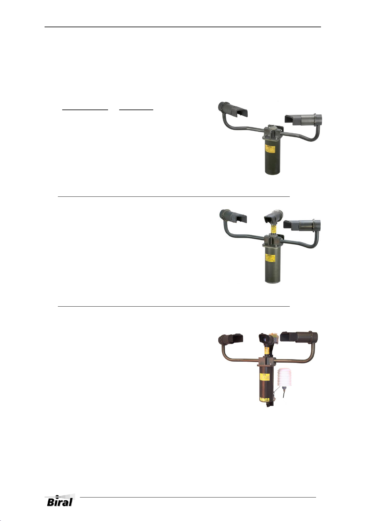
VPF-710 Visibility
VPF-730 Visibility
Precipitation type identification
This model has an extra backscatter receiver for:
Rain rate
Snowfall rate
Precipitation accumulation
VPF-750 Visibility
Precipitation type identification
This model has an extra precipitation sensor and
an extra high accuracy temperature and humidity
sensor for:
50 weather codes (from WMO
Code Table 4680), including:
Past Weather
Freezing Rain
Ice Pellets
This manual suits for next models
3
Table of contents
Other Biral Accessories manuals


