Birch Carisma IT7000III User manual

®Copyright 2010 July All Rights Reserved Version1.1
The information contained in this document is subject to change without notice. We make no warranty of any
kind with regard to this material, including, but not limited to, the implied warranties of merchantability
and fitness for a particular purpose. We shall not be liable for errors contained herein or for incidental
or consequential damages in connection with the furnishing, performance, or use of this material.
This document contains proprietary information that is protected by copy right. All rights are reserved. No
part of this document may be photocopied, reproduced or translated to another language without the prior
written consent of the manufacturer.
TRADEMARK
Intel®, Pentium® and MMX are registered trademarks of Intel® Corporation. Microsoft® and Windows® are
registered trademarks of Microsoft Corporation.
Small foot print & Elegant

1
Main Board
CPU
IT7000III-15 Intel® CoreTM2 Duo, Pentium 1.46GHz (T2310)
Chipset Intel® GME 965 Express + ICH8M
System Memory Total up to 4GB
Socket-type RAM device, 200PIN SO-DIMM DDR2 RAM, up to 2GB
On-board DDR2 RAM device, up to 2GB
Graphic Memory Shared system memory up to 256MB
LCD Panel
IT7000-15
Panel Size 15”
Maximum Resolution 1024 x 768
Brightness 250 cd/m1
Contrast Ratio 600 : 1
Response Time 8 ms
View Angles (H/V) 160 / 160
Touch Panel Five Wires Resistive
IT7000-12
Panel Size 12.1”
Maximum Resolution 1024 x 768
Brightness 195 cd/m1
Contrast Ratio 400 : 1
Response Time 16 ms
View Angles (H/V) 90 / 65
Touch Panel Five Wires Resistive
Storage
HDD 2.5” SATA interface
Compact Flush Type Ⅰ&Ⅱ
Expansion
Mini-PCIE Socket One
1

2
Power
Power Adaptor Input AC 100-240V 2.5A 50/60Hz, Output DC 12V 6.66A
I / O
USB Six
Serial Four COM ports with RJ-45 Connector
Pin 9 with 5V / 12V power selectable
Parallel One LPT with adaptor cable
LAN One
2nd VGA Output One with optional adaptor cable
PS/2 One
Audio One Earphone & One Microphone
Control/Indicator
Power Button One
LED Indicators Power (Green), HDD (Red), LAN(Orange)
Optional Peripherals
Magnetic Card Reader ISO Track 1/2/3, USB interface
VFD customer display 20 x 2 characters, RS-232 interface
Dimensions
IT-7000-15 358(W) X 367(L) X 173(H) mm
IT-7000-12 293(W) X 299(L) X 173(H) mm
Environment
Operating Temperature 0°C ~ 40°C ( 32°F ~ 104°F )
Storage Temperature - 20°C ~ 60°C ( - 4°F ~ 140°F )
Operating Humidity 10% - 80% RH non condensing
Storage Humidity 10% - 80% RH non condensing
Model Number
IT7000IIIX – SS Intel® CoreTM2 Duo, Pentium 1.46GHz (T2310)
X : M --- Shinny Black housing
Q --- Dull Black housing
W – Shinny White housing
SS: 15 --- 15"TFT LCD
12 --- 12"TFT LCD

3
If any item is missing, please contact your sale agent immediately.
Take the system unit out from the carton. Remove the unit by carefully holding the foam inserts and remove slowly to
protect the system. The following items should be found in the carton:
1. CD that including all
driver and manual
2. The System
. Power Adaptor 4. AC Power Cord
5. Printer Port conversion cable 6. Two RS-232 port
conversion cables
2

4
Please unplug the AC power of the adapter before opening any part of the system. Since the
standby power is always on after the adapter is plugged in. It may cause permanent damage
to your system when you open any part of it.
Front View
Side USB
Power
HDD
LAN
Power
Button
Rear View
Slot for installing
Magnetic Card
Reader (optional)
Hard Disk Cover
Cable Cover
Slot for installing
Custom Display
(optional)
3

5
How to open the connector bezel
Please unplug the AC power of the adapter before opening any part of the system.
Since the standby power is always on after the adapter is plugged in.
It may cause permanent damage to your system when you open any part of it.
As illustrated in
the following,
Move these two sides upward
Push the locker downward
Move these two sides upward

6
The connector panel
Please notice that all Four COM ports using RJ-45 connector and two RJ-45 to
DB-9 conversion cables are provided in the package.
Please notice that the Printer and VGA connectors in the second level, using JST PHD pitch
1.25 type connectors. The package includes a Printer Port adapter cable to connect to this connector
and a centronic connector. The VGA, Audio adapter is optional accessory.

7
Please unplug the AC power of the adapter before opening any part of the system. Since the
standby power is always on after the adapter is plugged in. It may cause permanent damage
to your system when you open any part of the system.
Installing Peripherals
To install the peripheral’s cables, please follow the method described below.
It will make the process much easier.
1. Turn the system upside down and Open
the cable cover as mentioned in the
former chapter.
2. Plug in the cables
3. Lock the metal foot 4. Turn the system back to normal direction
and let the cables coming out from the
opening of the bottom stand.
5. Then close the cable cover.
4

8
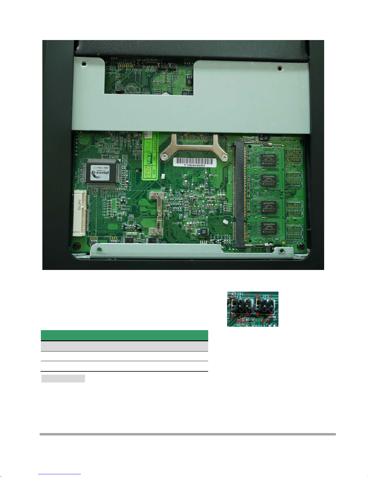
Jumper Setting and Reset the Main Board BIOS Setting
The jumper you can select COM3 to COM4 9 with 5V or 12V power. The second jumper is
Clean CMOS.
1. Release the four screws in the front panel.
2. Sometime, if the CPU front panel is too tight, it is easier to use a tweezers as a hook to pull the
panel out.
9
Jumper: JP1(COM4)/JP2(COM3)
Type: onboard 3 x 2-pin header
JP1/JP2 Mode
5-6 Standard COM Port
3-4 Pin9 with 12V signal
1-2 Pin9 with 5V signal
Default setting
JP2JP1
CMOS

10
Jumper: JRTC
Type: Onboard 3-pin jumper
Normal Operation Mode
1-2 Clear CMOS
2-3 Normal Operation
Default setting
After changing RAM module, please lock the four screws for front housing
1
11
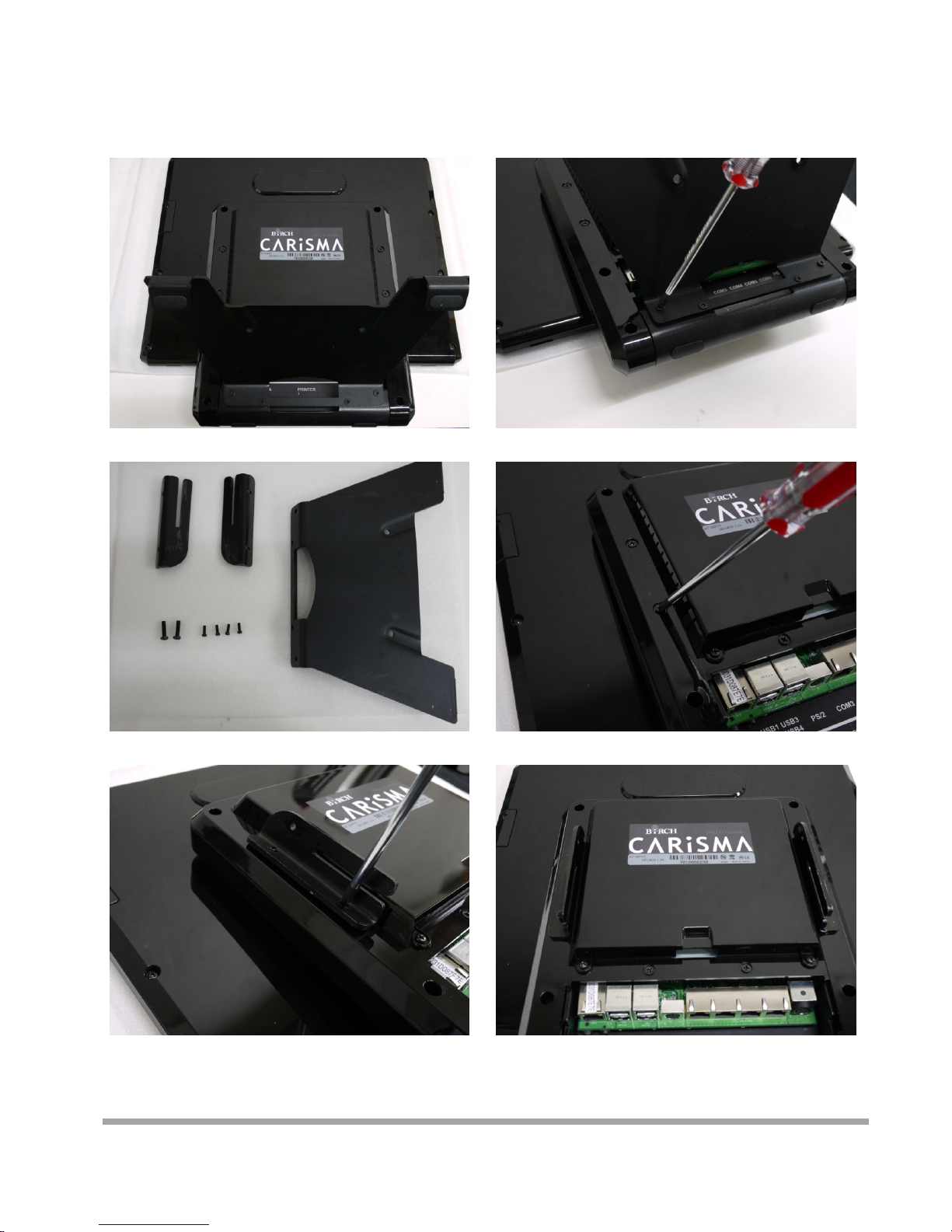
Mount CARiSMA on Wall
1. Turn the system upside down 2. Release metal foot
3. Release the screw
4. Lock the Wall mount by screw 5. It is the same procedure to lock
right side wall mount

12
5. Mark the signal 6. Drill the hole on the wall
9. Lock the CARiSMA by screw
A
ttention: Please check the
screw is lower than metal foot
7. Lock the metal foot on the wall 8. Insert the machine down from
Upper side
13
Installing Magnetic Card Reader (MSR)
1. Turn the system upside down 2. Open the cover of MSR cable
3. Connect the cable to MSR
4. Lock the screw to mount MSR

14
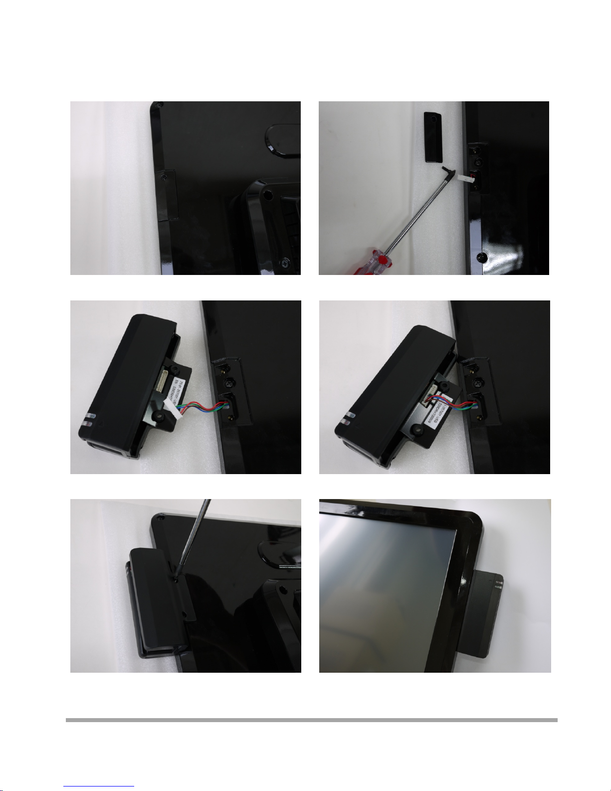
Installing Customer Display
1. Release Four screw on the back of VFD module
2. Release Two screw

15
3. Release the screws on the VFD module
4. Release the VFD board
5. Turn the system upside down
6. Open the VFD cover by fingernail

16
7. Pass the signal line through the middle of
the lower hinge mount hole
8. Pass the signal line through the middle of
the upper of hinge mount hole
10. Pass the signal line through the middle of
the VFD base
11. Connect the signal line with VFD board
9. Lock the hinge mount by screw

17
13. Close the VFD cover
Att
en
ti
on:
M
a
k
e sure
l
a
t
c
h
es are secure
l
y
15. Install hinge cover 16. Lock the hinge cover by screw
14. Lock the VFD cover with VFD base
12. Lock the VFD board by screws

18
17. Lock the VFD module with hinge mount

19
Installing Hard Disk
Please unplug the AC power of the adapter before opening the hard disk cover. Since the
standby power is always on after the adapter is plugged in. It may cause permanent damage
to your system when you open any part of the system.
1. Release these two screws of the hard disk cover.
2. After remove the hard disk cover, you will
find the 2.5” hard disk
Table of contents
Other Birch Desktop manuals


