Birch Carisma User manual

®Copyright 2010 July All Rights Reserved Version 2.0
The information contained in this document is subject to change without notice. We make no warranty of any
kind with regard to this material, including, but not limited to, the implied warranties of merchantability
and fitness for a particular purpose. We shall not be liable for errors contained herein or for incidental
or consequential damages in connection with the furnishing, performance, or use of this material.
This document contains proprietary information that is protected by copy right. All rights are reserved. No
part of this document may be photocopied, reproduced or translated to another language without the prior
written consent of the manufacturer.
TRADEMARK
Intel®, Pentium® and MMX are registered trademarks of Intel® Corporation. Microsoft® and Windows® are
registered trademarks of Microsoft Corporation.
Small foot print & Elegant

1
Main Board
CPU
IT7000V0-15 Intel® Pentium® Processor 2117U (2M Cache, 1.80 GHz)
Chipset Intel® HM70 Express
System Memory Socket-type RAM device, 204PIN SO-DIMM DDR3 1333 / 1600 RAM, up to 8GB
Graphic Memory Shared system memory up to 256MB
LCD Panel
IT7000V0-15
Panel Size 15”
Maximum Resolution 1024 x 768
Brightness 250 cd/m1
Contrast Ratio 600 : 1
Response Time 8 ms
View Angles (H/V) 160 / 160
Touch Panel Five Wires Resistive
Storage
HDD 2.5” SATAIII interface
Expansion
Socket One Mini-PCIE or One Msata II
Power
Power Adaptor Input AC 100-240V 2.5A 50/60Hz, Output DC 12V 6.66A
I / O
USB Six
Serial Four COM ports with RJ-45 Connector
Pin 9 with 5V / 12V power selectable
Parallel One LPT with adaptor cable
LAN One
2nd VGA Output One with optional adaptor cable
PS/2 One
1

2
Audio One Earphone & One Microphone
Cash Drawer One with optional adapter
Control/Indicator
Power Button One
LED Indicators Power (Green), HDD (Red), LAN(Orange)
Optional Peripherals
Magnetic Card Reader ISO Track 1/2/3, USB interface
VFD customer display 20 x 2 characters, RS-232 interface
Dimensions
IT-7000V0-15 358(W) X 367(L) X 173(H) mm
Environment
Operating Temperature 0°C ~ 40°C ( 32°F ~ 104°F )
Storage Temperature - 20°C ~ 60°C ( - 4°F ~ 140°F )
Operating Humidity 10% - 80% RH non condensing
Storage Humidity 10% - 80% RH non condensing
Model Number
IT7000VX – SS Intel® Pentium® Processor 2117U
X : M --- Shinny Black housing
Q --- Dull Black housing
W – Shinny White housing
SS: 15 --- 15"TFT LCD

3
If any item is missing, please contact your sale agent immediately.
Take the system unit out from the carton. Remove the unit by carefully holding the foam inserts and remove slowly to
protect the system. The following items should be found in the carton:
1. CD that including all
driver and manual
2. The System
. Power Adaptor 4. AC Power Cord
5. Printer Port conversion cable 6. Two RS-232 port
conversion cables
2

4
Please unplug the AC power of the adapter before opening any part of the system. Since the
standby power is always on after the adapter is plugged in. It may cause permanent damage
to your system when you open any part of it.
Front View
Side USB
Power
HDD
LAN
Power
Button
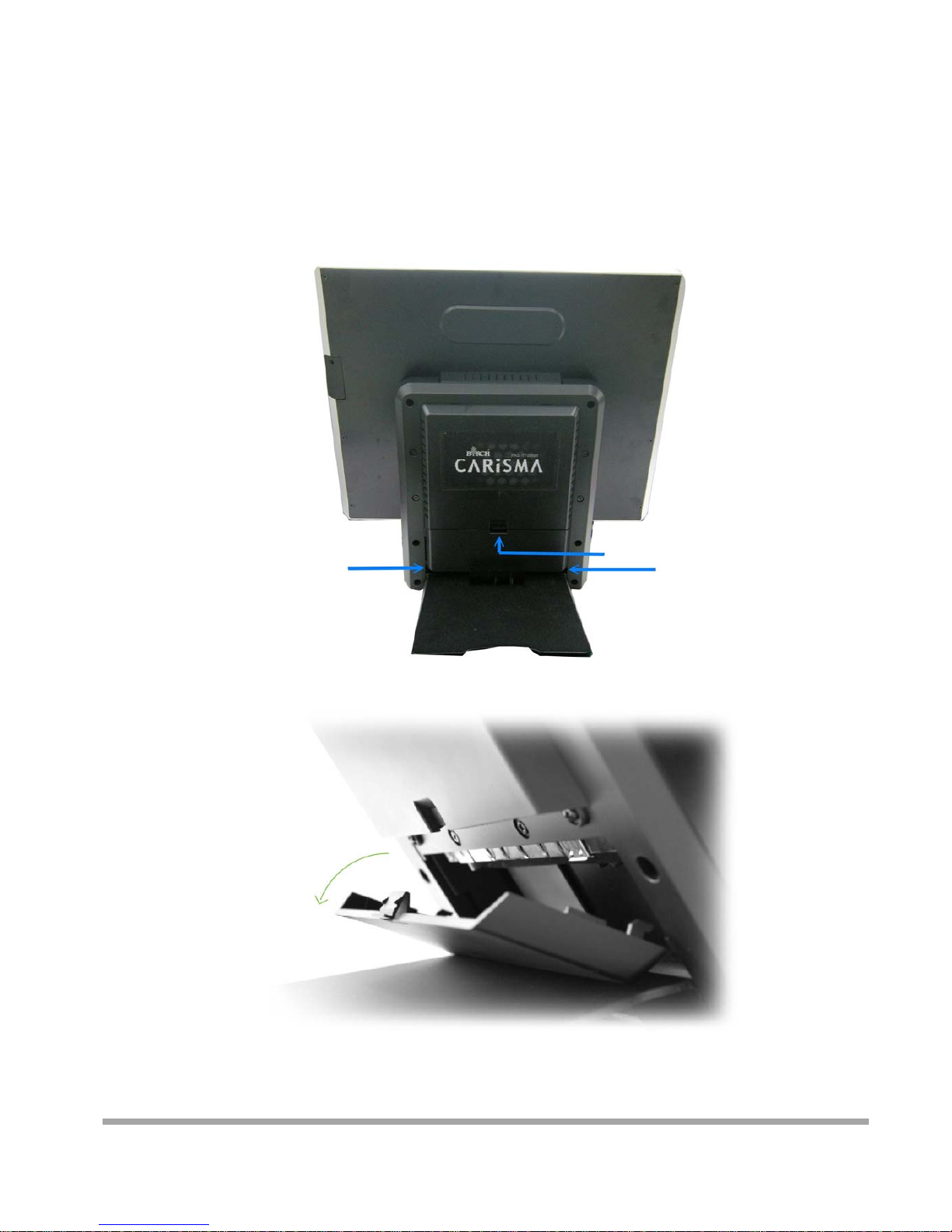
Rear View
Slot for installing
Magnetic Card
Reader (optional)
Hard Disk Cover
Cable Cover
Slot for installing
Custom Display
(optional)
3
5
How to open the connector bezel
Please unplug the AC power of the adapter before opening any part of the system.
Since the standby power is always on after the adapter is plugged in.
It may cause permanent damage to your system when you open any part of it.
As illustrated in
the following,
Move these two sides upward Push the locker downward
Move these two sides upward
6
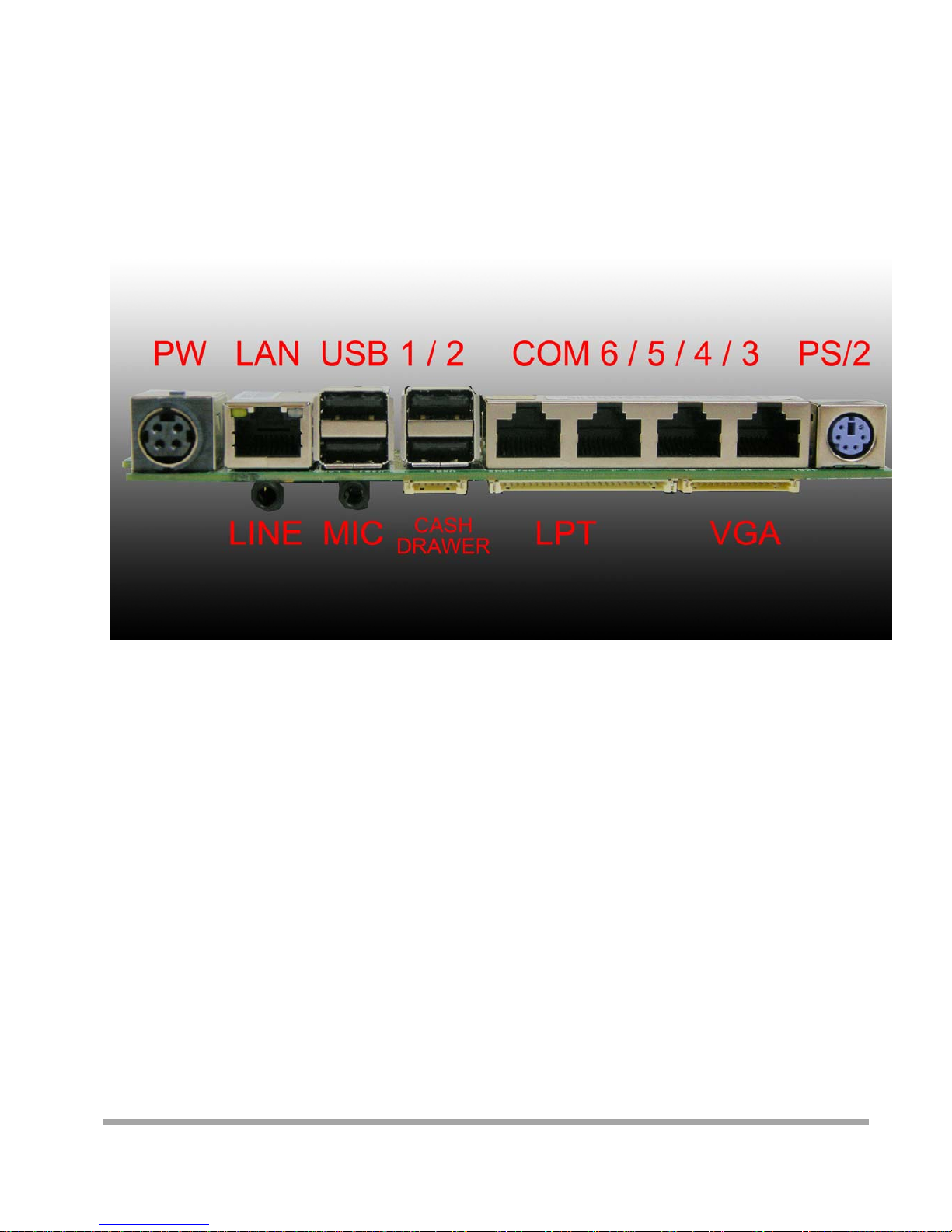
The connector panel
Please notice that all Four COM ports using RJ-45 connector and two RJ-45 to
DB-9 conversion cables are provided in the package.
Please notice that the Printer and VGA connectors in the second level, using JST PHD pitch
1.25 type connectors. The package includes a Printer Port adapter cable to connect to this connector
and a centronic connector. The VGA, Audio adapter is optional accessory.

7
Please unplug the AC power of the adapter before opening any part of the system. Since the
standby power is always on after the adapter is plugged in. It may cause permanent damage
to your system when you open any part of the system.
Installing Peripherals
To install the peripheral’s cables, please follow the method described below.
It will make the process much easier.
1. Turn the system upside down and Open
the cable cover as mentioned in the
former chapter.
2. Plug in the cables
3. Lock the metal foot 4. Turn the system back to normal direction
and let the cables coming out from the
opening of the bottom stand.
5. Then close the cable cover.
4

8
Installing Magnetic Card Reader (MSR)
1. Turn the system upside down 2. Open the cover of MSR cable
3. Connect the cable to MSR 4. Lock the screw to mount MSR
9
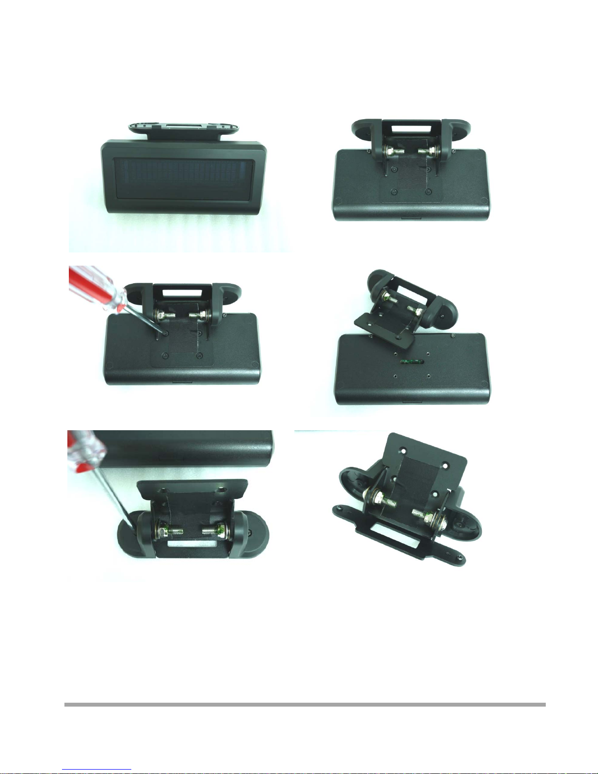
Installing Customer Display
1. Release Four screw on the back of VFD module
2. Release Two screw

10
3. Release the screws on the VFD module
4. Release the VFD board
5. Turn the system upside down
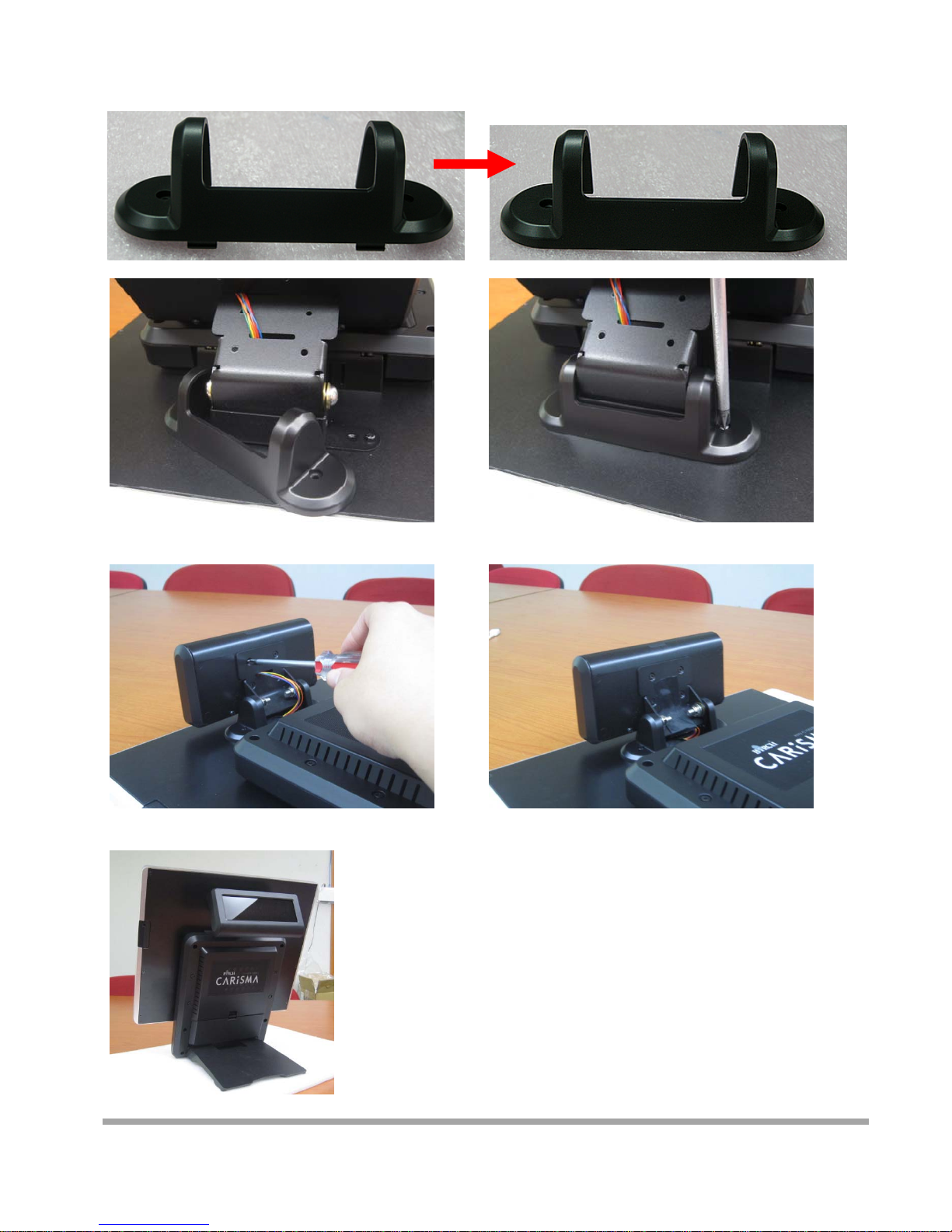
6. Open the VFD cover by fingernail

11
7. Pass the signal line through the middle of
the lower hinge mount hole
8. Pass the signal line through the middle of
the upper of hinge mount hole
9. Lock the hinge mount by screw
10. Pass the signal line through the middle of
the VFD base
11. Connect the signal line with VFD board

12
12. Lock the VFD board by screws
13. Close the VFD cover
Att
en
ti
on:
M
a
k
e sure
l
a
t
c
h
es are secure
l
y
15. Cut two plastic sheets 14. Lock the VFD cover with VFD base
13
16. Install hinge cover 17. Lock the hinge cover by screw
18. Lock the VFD module with hinge mount 19. Taped
14
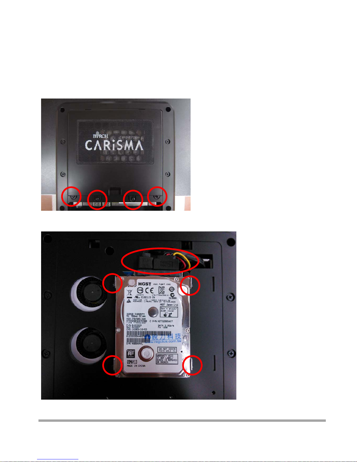
Installing Hard Disk
Please unplug the AC power of the adapter before opening the hard disk cover. Since the
standby power is always on after the adapter is plugged in. It may cause permanent damage
to your system when you open any part of the system.
1. Release these two screws of the hard disk cover.
2. After remove the hard disk cover, you will
find the 2.5” hard disk
15
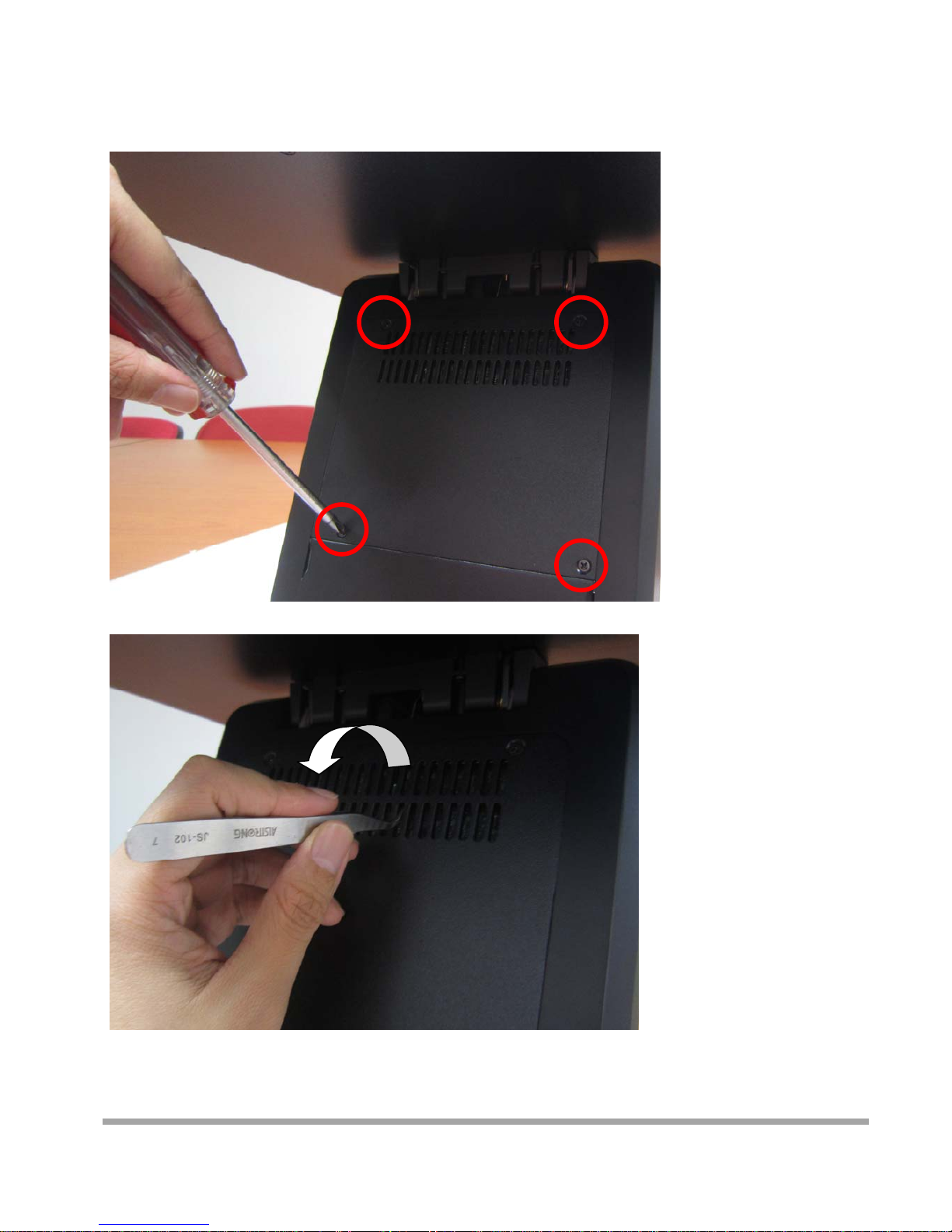
Installing RAM
1. Release the four screws in the front housing.
2. Sometime, if the CPU front panel is too tight, it is easier to use a tweezers as a hook to pull the
panel out.

16
3. After changing RAM module, please lock the four screws for front housing
17
Introducing BIOS
Notice! The BIOS options in this manual are for reference only.
Different configurations may lead to difference in BIOS screen
and BIOS screens in manuals are usually the first BIOS version when the board is
released and may be different from your purchased motherboard.
Users are welcome to download the latest BIOS version form our official website.
The BIOS is a program located on a Flash Memory on the motherboard. This program is a bridge
between motherboard and operating system. When you start the computer, the BIOS program will
gain control. The BIOS first operates an auto-diagnostic test called POST (power on self test) for all
the necessary hardware, it detects the entire hardware device and configures the parameters of
the hardware synchronization. Only when these tasks are completed done it gives up control of
the computer to operating system (OS). Since the BIOS is the only channel for hardware
and software to communicate, it is the key factor for system stability, and in ensuring that your
system performance as its best.
Entering Setup
Power on the computer and by pressing <Del> immediately allows you to enter Setup. If the
message disappears before your respond and you still wish to enter Setup, restart the system to
try again by turning it OFF then ON or pressing the “RESET” button on the system case. You may
also restart by simultaneously pressing <Ctrl>, <Alt> and <Delete> keys. If you do not press
the keys at the correct time and the system does not boot, an error message will be
displayed and you will again be asked to Press <Del> to enter Setup
5

18
BIOS Menu Screen
The following diagram show a general BIOS menu screen:
Function Key
In the above BIOS Setup main menu of, you can see several options. We will explain these options
step by step in the following pages of this chapter, but let us first see a short description of the
function keys you may use here:
Press←→ (left, right) to select screen
Press ↑↓ (up, down) to choose, in the main menu, the option you want to confirm or to modify.
Press <Enter> to select.
Press <+>/<–> keys when you want to modify the BIOS parameters for the active option.
[F1]: General help.
[F2]: Previous value.
[F3]: Optimized defaults.
MenuBar
MenuItems
CurrentSettingValue
GeneralHelpItems
FunctionsKeys

19
[F4]: Save & Reset.
Press <Esc> to quit the BIOS Setup.
Getting Help
Main Menu
The on-line description of the highlighted setup function is displayed at the top right corner the
screen.
Status Page Setup Menu/Option Page Setup Menu
Press F1 to pop up a small help window that describes the appropriate keys to use and the
possible selections for the highlighted item. To exit the Help Window, press <Esc>.
Menu Bar
There are six menu bars on top of BIOS screen:
Main To change system basic configuration
Advanced To change system advanced configuration
Chipset To change chipset configuration
Boot To change boot settings
Security Password settings
Save & Exit Save setting, loading and exit options.
User can press the right or left arrow key on the keyboard to switch from menu bar. The
selected one is highlighted.
Other manuals for Carisma
1
Table of contents
Other Birch Desktop manuals


