Birch 854 User manual
BIRCH 854
Mini Barebone system
Intel D510 High Performance Platform
Installation Guide
Edition 1.0
2010/8/31

Document Content:
Packing List
Product Specification
Hardware Installation
Packing List:
BIRCH 854 Chassis x 1
(Including D510MO Motherboard)
DSPD-080-12A 80W AC-DC Adapter x 1
Power Cord x 1
ATAPI Power Cord x1
SATA Cable x 1
ATX to SATA Power Cable x 1
CD Driver x1
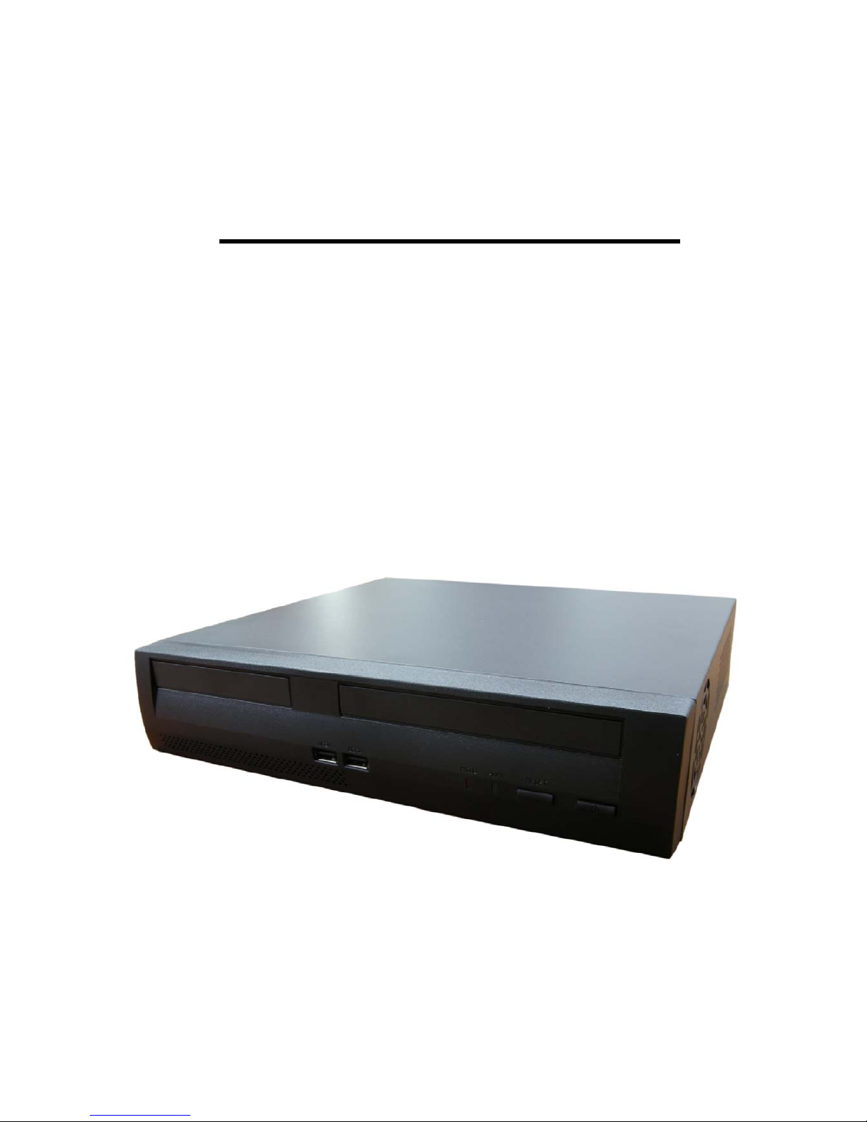
BIRCH 854

Power Button
HD LED
Hardware Installation:
I/O panel:
Front:
Rear panel:
Reset Button
Power LED
US
B
COM3COM4
PRINTER PORT
RJ-45
Mouse
Keyboard
VGA USB
USB
COM1COM2
Line-out
Mic-in
Line-in
DC IN
Antenna

Processor
Birch 854 includes a passively-cooled, dual-core Intel Atom processor with integrated graphics and
memory controller. The processor is soldered to the Desktop Board and is not customer upgradeable.
NOTE
The board is designed to be passively cooled in a properly ventilated chassis. Chassis venting locations
are recommended above the processor heatsink area for maximum heat dissipation effectiveness.
System Memory
NOTE
To be fully compliant with all applicable Intel® SDRAM memory specifications, the board should be
populated with DIMMs that support the Serial Presence Detect (SPD) data structure. If your memory
modules do not support SPD, you will see a notification to this effect on the screen at power up. The
BIOS will attempt to configure the memory controller for normal operation.
The Desktop Board has two 240-pin DDR2 DIMM connectors with gold-plated contacts.
It supports:
• DDR2 800 MHz or DDR2 667 MHz unbuffered, non-registered DIMMs
• Serial Presence Detect (SPD) memory only
• Non-ECC memory
• Up to 4 GB of memory
Integrated Graphics Subsystem
The integrated Intel GMA 3150 graphics controller features the following:
• 400 MHz core frequency
• High quality texture engine
ۛ DX9.0c* and OpenGL* 1.4 compliant
ۛ Hardware Pixel Shader 2.0
ۛ Vertex Shader Model 2.0
• 3D Graphics Rendering enhancements
ۛ 1.6 dual texture GigaPixel/s max fill rate
ۛ 16-bit and 32-bit color
ۛ Vertex cache
• Video
ۛ Software DVD at 30 fps full screen
ۛ DVMT support up to 256 MB
• Supports analog displays up to 2048 x 1536 at 75 Hz refresh (QXGA)
Intel® NM10 Express Chipset
The Intel NM10 Express Chipset is a centralized controller for the board’s I/O paths.
For more information about the Intel NM10 Express Chipset, go to

http://www.intel.com/products/chipsets/index.htm?iid=prod+prod_chipset.
Operating System Support
The following Microsoft* operating systems are fully supported by the Desktop Board:
• Microsoft Windows Vista* Home Basic, SP 1
• Microsoft Windows* XP Home, SP 3
• Microsoft Windows* 7 Home Basic and Starter
Onboard Audio Subsystem
The Birch 854 6-channel (5.1) onboard audio subsystem supports both Intel HD Audio and AC ’97 Audio.
The subsystem is based on the following
components:
• Intel NM10 Express Chipset
• RealTek ALC662 audio codec
The subsystem includes the following headers and connectors:
• Front panel audio header (supports both Intel HD Audio and AC ’97) , including
functionality for:
―Line out (headphones/speaker)
―Microphone in
• Three back panel analog audio jacks
• Onboard S/PDIF output header (3 pin)
Legacy Input/Output (I/O) Controller
The legacy I/O controller provides the following:
• Two serial ports (via onboard headers)
• One parallel port with Extended Capabilities Port (ECP) and Enhanced Parallel Port
(EPP) support via an onboard headers
• Serial IRQ interface compatible with serialized IRQ support for PCI systems
• PS/2-style keyboard and mouse ports
• Intelligent power management, including a programmable wake up event interface
• PCI power management support
The BIOS Setup program provides configuration options for the legacy I/O controller.
LAN Subsystem
The LAN subsystem consists of the following:
• Intel NM10 Express Chipset
• Realtek 8111DL Gigabit Ethernet Controller for 10/100/1000 Mbits/s Ethernet LAN
connectivity
• RJ-45 LAN connector with integrated status LEDs
Additional features of the LAN subsystem include:
• CSMA/CD protocol engine
• LAN connect interface that supports the ethernet controller

• PCI bus power management
ۛ Supports ACPI technology
ۛ Supports LAN wake capabilities
LAN drivers are available from Intel’s World Wide Web site at
http://downloadcenter.intel.com/.
USB 2.0 Support
The Desktop Board supports up to seven USB 2.0 ports (four ports routed to the back panel and three
ports routed to two front panel USB 2.0 headers). One of the front panel USB headers supports an Intel
Z-U130 USB Solid-State Drive (or compatible device). The USB 2.0 ports are compatible with USB 1.1
devices. USB 1.1 devices will function normally at USB 1.1 speeds.
USB 2.0 support requires both an operating system and drivers that fully support USB 2.0 transfer
rates. Disabling High-Speed USB in the BIOS reverts all USB 2.0 ports to USB 1.1 operation. This may
be required to accommodate operating systems that do not support USB 2.0.
NOTE
Computer systems that have an unshielded cable attached to a USB port might not meet FCC Class B
requirements, even if no device or a low-speed USB device is attached to the cable. Use a shielded
cable that meets the requirements for a full-speed USB device.
SATA Interface
The Desktop Board supports two SATA channels (3.0 Gb/s) that support one device per channel. The
SATA controller supports IDE and ACHI configuration and can operate in both legacy and native modes.
Expandability
The Desktop Board provides the following expansion capability:
• One PCI connector. The connector can support either a single PCI add-in card or a
single- or dual-slot PCI riser card.
• One PCI Express Full-Mini Card slot.
BIOS
The BIOS provides the Power-On Self-Test (POST), the BIOS Setup program, the PCI and IDE
auto-configuration utilities, and the video BIOS.
PCI/PCI Express Auto Configuration
If you install a PCI/PCI Express add-in card in your computer, the PCI/PCI Express auto-configuration
utility in the BIOS automatically detects and configures the resources (IRQs, DMA channels, and I/O
space) for that add-in card. You do not need to run the BIOS Setup program after you install a PCI/PCI
Express add-in card.
Security Passwords
The BIOS includes security features that restrict whether the BIOS Setup program can be accessed and
who can boot the computer. A supervisor password and a user password can be set for the BIOS Setup

and for booting the computer, with the following restrictions:
• The supervisor password gives unrestricted access to view and change all Setup options. If only the
supervisor password is set, pressing <Enter> at the password prompt of Setup gives the user restricted
access to Setup.
• If both the supervisor and user passwords are set, you must enter either the supervisor password or
the user password to access Setup. Setup options are then available for viewing and changing
depending on whether the supervisor or user password was entered.
• Setting a user password restricts who can boot the computer. The password prompt is displayed
before the computer is booted. If only the supervisor password is set, the computer boots without
asking for a password. If both passwords are set, you can enter either password to boot the computer.
Power Management Features
Power management is implemented at several levels, including:
• Software support through the Advanced Configuration and Power Interface (ACPI)
• Hardware support:
―Power connector
―Fan header
―+5 V standby power indicator LED
―LAN Wake capabilities
―Instantly Available PC technology
―Wake from USB
―Wake from PS/2 devices
―PME# wakeup support
―WAKE# signal wakeup support
―Wake from serial port
ACPI
ACPI gives the operating system direct control over the power management and Plug and Play
functions of a computer. The use of ACPI with the Desktop Board requires an operating system that
provides full ACPI support.
Hardware Support
Fan Header
The Desktop Board has a 3-pin chassis fan header. See Figure 13 on page 39 for the location of the
chassis fan header.
+5 V Standby Power Indicator
CAUTION
If the AC power has been switched off and the standby power indicator is still lit, disconnect the power
cord before installing or removing any devices connected to the board. Failure to do so could damage
the board and any attached devices.
Instantly Available PC Technology
Instantly Available PC technology enables the board to enter the ACPI S3 (Suspend-to- RAM)

sleep-state. While in the ACPI S3 sleep-state, the computer will appear to be off (the hard drive(s) and
fan will power off, the front panel power LED will blink). When signaled by a wake-up device or event,
the system quickly returns to its last known state.
The board supports the PCI Bus Power Management Interface Specification. Add-in boards that also
support this specification can participate in power management and can be used to wake the computer.
The use of Instantly Available PC technology requires operating system support and PCI 2.3 compliant
add-in cards and drivers.
LAN Wake Capabilities
The board’s LAN wake capabilities enable remote wake-up of the computer through a network. The LAN
subsystem network adapter monitors network traffic at the Media Independent Interface. The board
supports LAN wake capabilities with ACPI in the following ways:
• By Ping
• By Magic Packet
Upon detecting the configured wake packet type, the LAN subsystem asserts a wakeup signal that
powers up the computer.
Wake from USB
USB bus activity wakes the computer from an ACPI S1 or S3 state.
NOTE
Wake from USB requires the use of a USB peripheral that supports wake from USB.
Wake from PS/2 Device
PS/2 keyboard activity wakes the computer from an ACPI S1, S3, S4, or S5 state. However, when the
computer is in an ACPI S4 or S5 state, the only PS/2 activity that will wake the computer is the Alt +
Print Screen key combination or the Power key available only on some keyboards.
PME# Wakeup Support
When the PME# signal is asserted on the PCI bus, the computer wakes from an ACPI S1, S3, S4, or S5
state.
WAKE# Signal Wakeup Support
When the WAKE# signal is asserted on the PCI Express bus, the computer wakes from an ACPI S1, S3,
S4, or S5 state.
Wake from Serial Port
Serial port activity wakes the computer from an ACPI S1 or S3 state.

<Installing Memory>
NOTE
To be fully compliant with all applicable Intel SDRAM memory specifications, the
boards require DIMMs that support the Serial Presence Detect (SPD) data structure.
The Desktop Board has two 240-pin DDR2 DIMM sockets.
1. Turn off all peripheral devices connected to the computer. Turn off the computer
and disconnect the AC power cord.
2. Remove the computer’s cover and locate the DIMM socket
3. Make sure the clips at either end of the DIMM socket are pushed outward to the open position.
4. Position the DIMM above the socket. Align the small notch at the bottom edge of the DIMM with the
key in the socket.
5. Insert the bottom edge of the DIMM into the socket.
6. When the DIMM is inserted, push down on the top edge of the DIMM until the retaining clips snap into
place. Make sure the clips are firmly in place.
7. Replace the computer’s cover and reconnect the AC power cord.

<Connecting SATA Drives>
The board has two SATA connectors each supporting one SATA drive. The included
SATA cables support the Serial ATA protocol. For correct cable and drive function:
1. Attach the locking cable end to the connector on the board.
2. Attach the cable end without the lock to the drive.
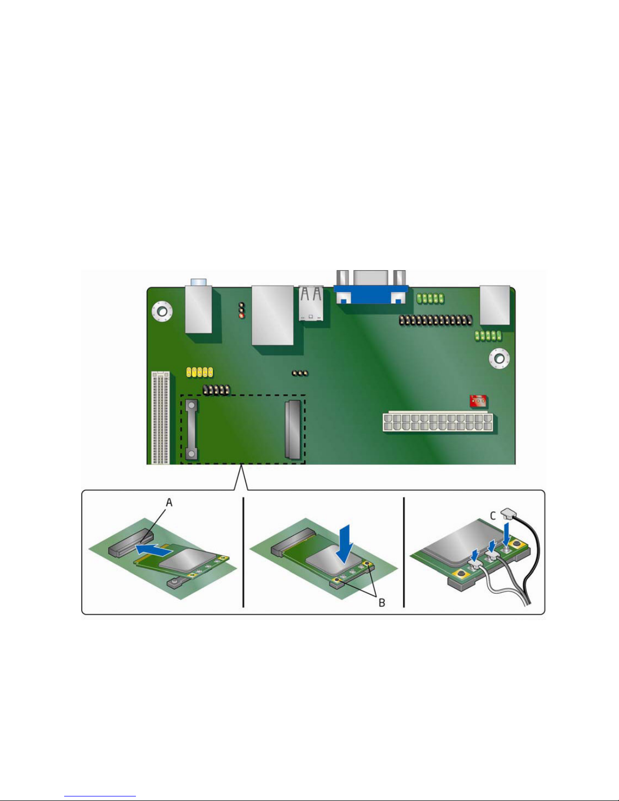
<Installing a Wireless LAN Card in the PCI>
A wireless LAN card can be installed in the Desktop Board’s PCI Express Full-Mini Card slot.
To install a wireless LAN card on the Desktop Board, see Figure 10 and follow these steps:
1. Locate the PCI Express Full-Mini Card slot.
2. Insert the wireless LAN card into the PCI Express Mini Card connector.
3. Align the mounting holes and snap the card in place.
4. Attach your system’s antenna wires to the connectors on the wireless LAN card as shown.
NOTE
External antennas can be connected through the I/O shield by removing any or all of the cut-outs above
the back panel I/O section.
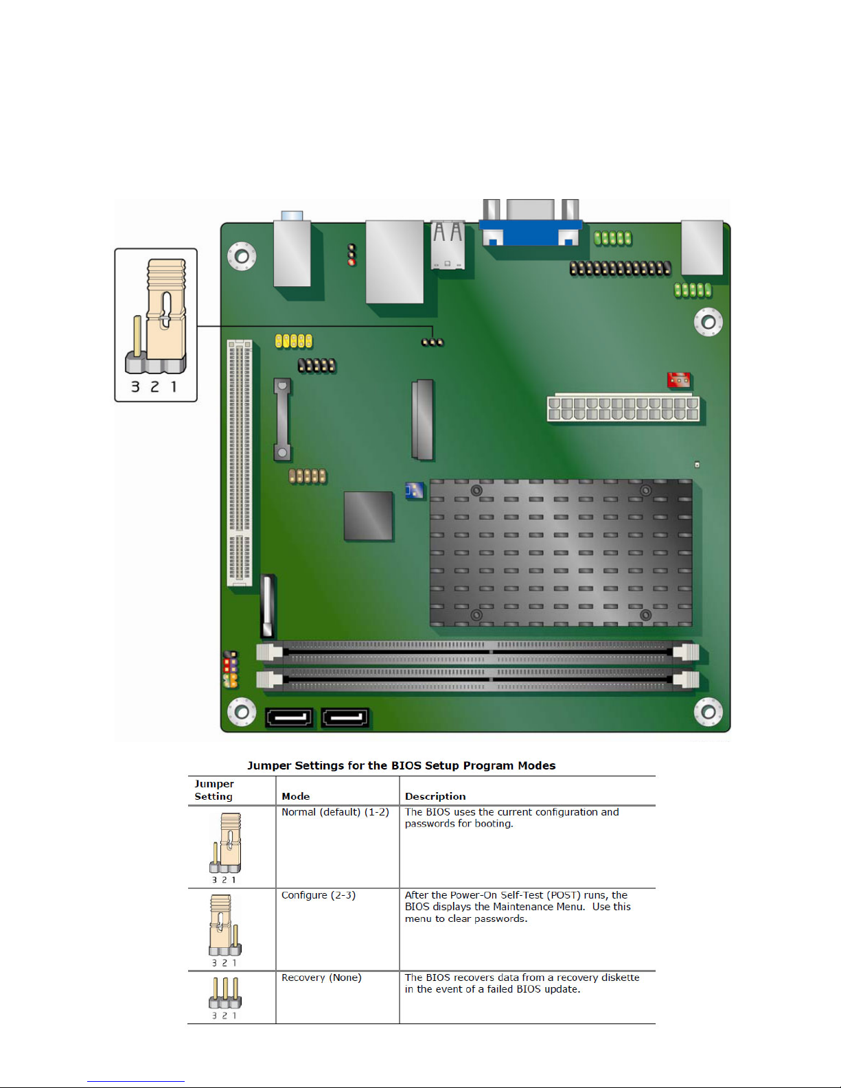
<Setting the BIOS Configuration Jumper>
NOTE
Always turn off the power and unplug the power cord from the computer before
changing a jumper. Moving the jumper with the power on may result in unreliable
computer operation.
Table of contents
Other Birch Desktop manuals


Popular Desktop manuals by other brands


Lenovo
Lenovo 0841A2U - Topseller A58e E5300 2.6G 2Gb 250Gb Dvdrw... Hardware Maintenance Manual

Control Data
Control Data 3100 Reference manual

Control Data Corporation
Control Data Corporation CYBER 170 Series Operator's guide

Sony
Sony VAIO VGX-XL1A release note

StudioDesk
StudioDesk XTRMB01 Assembly manual

Lenovo
Lenovo ThinkCentre M75s Gen2 Hardware Maintenance Manual


