Birch PP-8100-15 User manual

®Copyright 2015 July All Rights Reserved Version 1.0
The information contained in this document is subject to change without notice. We make no warranty of any
kind with regard to this material, including, but not limited to, the implied warranties of merchantability
and fitness for a particular purpose. We shall not be liable for errors contained herein or for incidental
or consequential damages in connection with the furnishing, performance, or use of this material.
This document contains proprietary information that is protected by copy right. All rights are reserved. No part of
this document may be photocopied, reproduced or translated to another language without the prior
written consent of the manufacturer.
TRADEMARK
Intel®, Pentium® and MMX are registered trademarks of Intel® Corporation. Microsoft® and Windows® are
registered trademarks of Microsoft Corporation.
Always high-speed! absolutely desirable

Main Board
CPU
PP-8100-15 Intel® Bay trail Celeron J1900 Processor D/M Series (2M Cache, 2.0 GHz)
Chipset
Intel® SoC
System Memory
Max 2 DDR3L 1333 MHz SO-DIMM slots, up to 8GB
Graphic Memory
Intel® HD Graphics
LCD Panel
PP-8100-15
Panel Size 15”
Maximum Resolution 1024 x 768
Brightness 250 cd/m1
Contrast Ratio 700 : 1
Response Time 16 ms
View Angles (H/V) 150 / 120
Touch Panel Five Wires Resistive Touch or Projected Capacitive Touch
Storage
HDD 2.5” SATAIII interface x 1
Expansion
Socket One Mini-PCIE or One Msata II
Power
Power Adaptor Input AC 100-240V 2.5A 50/60Hz, Output DC 12V 6.66A
I / O
USB Six USB 2.0
Serial Three COM ports with DB-9 Connector
COM1 with 5V / 12V power selectable
LAN Max 2 Realtek 8111G Gigabit Fast Ethernet controllers
2nd VGA Output One 15 Pin VGA Port
PS/2 One
Audio Two Earphone & Two Microphone
1
1

Control/Indicator
Power Button One
LED Indicators Power (Red)
Optional Peripherals
Magnetic Card Reader ISO Track 1/2/3, USB interface
VFD customer display 20 x 2 characters, RS-232 interface
Dimensions
PP-8100-15 358(W) X 70(L) X 293(H) mm
PP-8100-T15 358(W) X 223.9(L) X 309.6(H) mm
Environment
Operating Temperature 0°C ~ 40°C ( 32°F ~ 104°F )
Storage Temperature - 20°C ~ 60°C ( - 4°F ~ 140°F )
Operating Humidity 10% - 80% RH non condensing
Storage Humidity 10% - 80% RH non condensing
Model Number
PP-8100 - X–SS Intel® Bay trail Celeron J1900 Processor D/M Series (2M Cache, 2.0 GHz)
X : T --- Contain foot
SS : 15 --- 15"TFT LCD
2

If any item is missing, please contact your sale agent immediately.
Take the system unit out from the carton. Remove the unit by carefully holding the foam inserts and remove slowly to protect
the system. The following items should be found in the carton:
1. CD that including all
driver and manual
2. The System
. Power Adaptor 4. AC Power Cord
2
3

Please unplug the AC power of the adapter before opening any part of the system. Since the
standby power is always on after the adapter is plugged in. It may cause permanent damage to
your system when you open any part of it.
Front View
3
Power
Button
Microphone
Earphone
USB 2.0
4

Rear View
Slot for installing
Magnetic Card
Reader (optional)
Cable Cover
Slot for installing
Custom Display
or Second Display
(optional)
VESA 75
VESA 100
5

How to open the connector bezel
Please unplug the AC power of the adapter before opening any part of the system.
Since the standby power is always on after the adapter is plugged in.
It may cause permanent damage to your system when you open any part of it.
As illustrated in
the following,
Move these two sides upward
Release the screw
6

The connector panel
1. TOP of machine
2. Bottom of machine
Hard Disk 2
Power IN
Earphone
Microphone
LAN
USB 2.0
USB 2.0
VGA
COM1
LAN
COM3
COM2
P S /2
Power Button
Microphone
Earphone
USB 2.0
Hard Disk 1
7

Please unplug the AC power of the adapter before opening any part of the system. Since the
standby power is always on after the adapter is plugged in. It may cause permanent damage to
your system when you open any part of the system.
Installing Peripherals
To install the peripheral’s cables, please follow the method described below.
It will make the process much easier.
1. Open the Cable cover and Hinge cover 2. Follow the way of drawing to wiring
Plug in all the cable on the hots
3. Through the cable between HOST and FOOT
4
8

Installing Magnetic Card Reader (MSR)
1. Remove the rubber mat,Loosen the screw,and remove the MSR cover
2. Connected to the cable on the MSR and host,and lock two screws
1
2
9

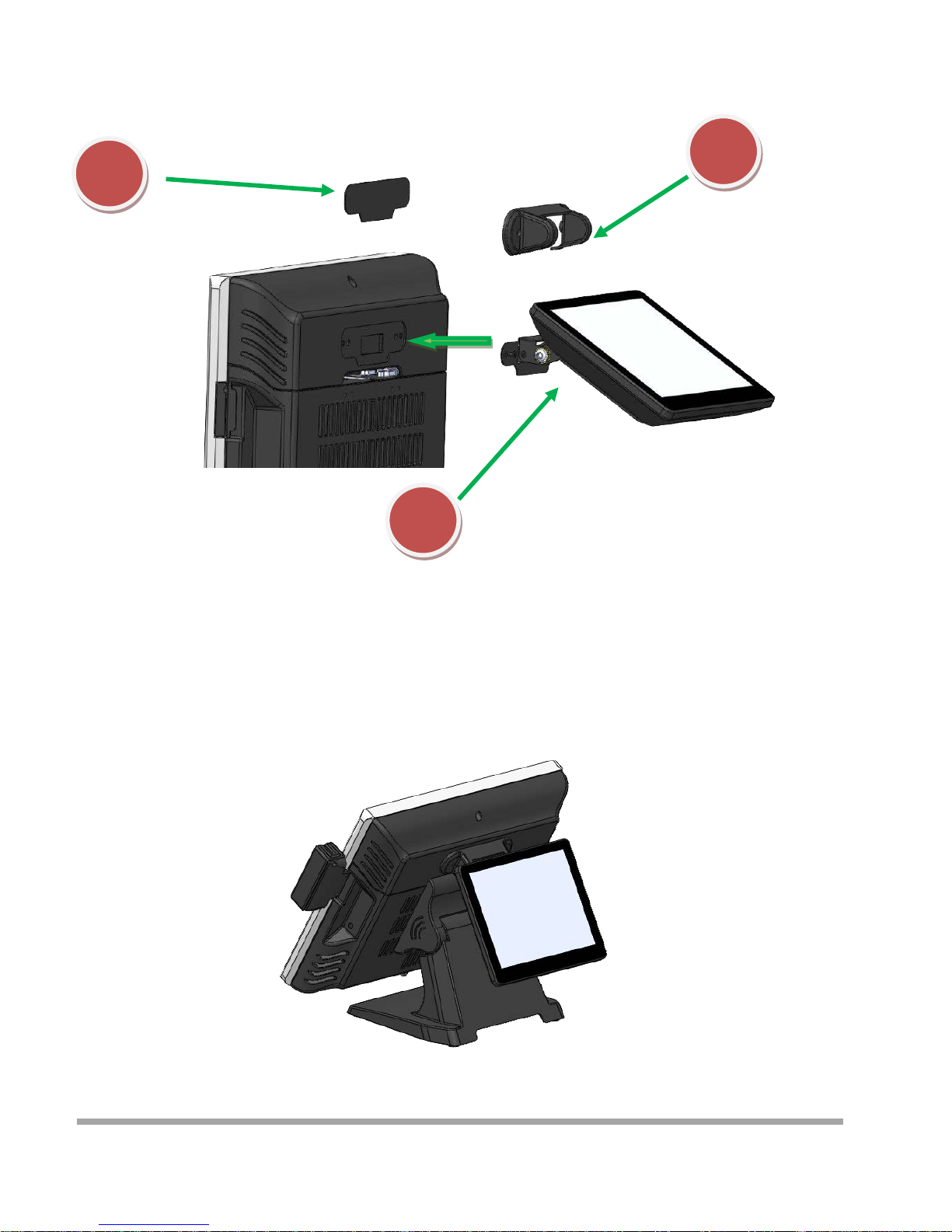
Installing Customer Display
1
2
3
1. Remove the metal bezel
2. Connected to the cable, lock the two screws on Cable Cover
3. Installation VFD cover and lock the two screws
10
Installing Second Display
1. Remove the metal bezel
2. Connected to the cable, lock the two screws on Cable Cover
3. Installing the cover and lock the two screws
1
2
3
11

Remove and Installing Hard Disk
1. Release the screw
4. Grab the handle and pull up or down
Remove or Installation Hard disk
2. Move these two sides upward
3. Release the screw
12
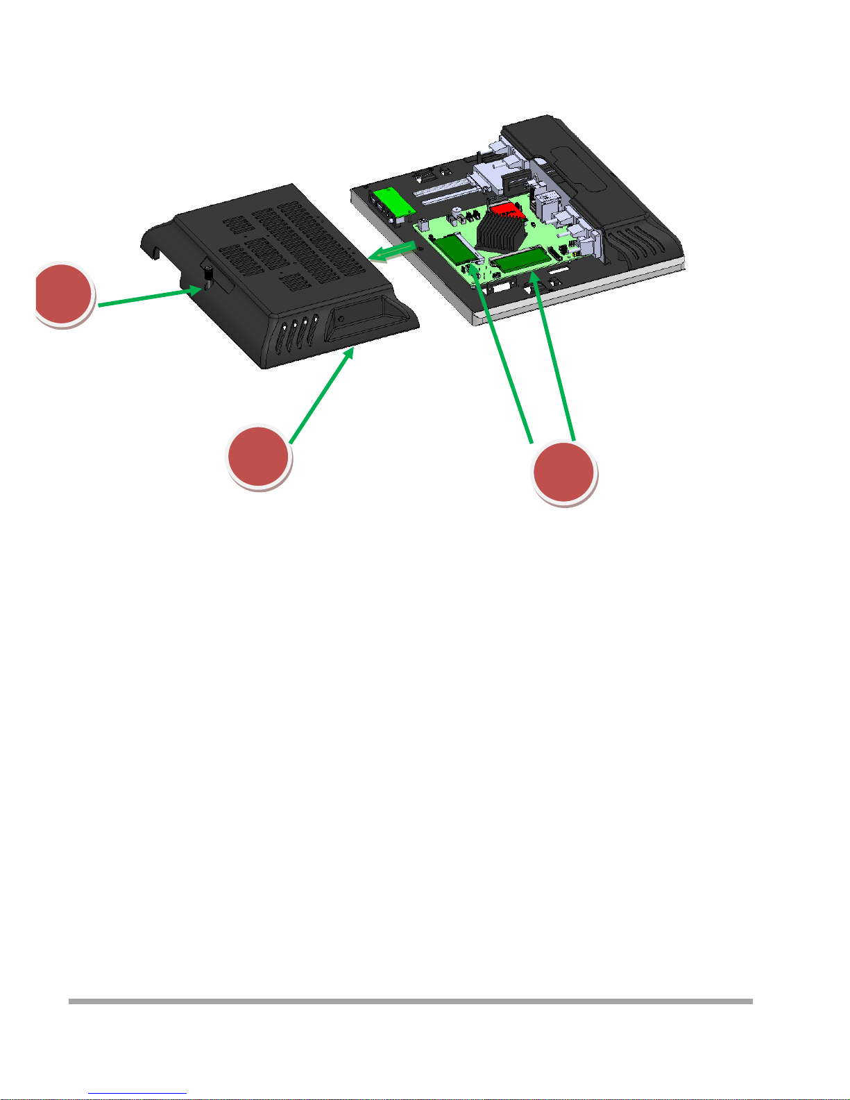
Remove and Installing Memory
1
2
1. Release the screw
2. Grasp the both sides , and pulled down the back cover
3. Replace or Installing Memory
3
13

Installing WIFI Card and Antenna
1
2
1. Release the screw
2. Grasp the both sides , and pulled down the back cover
3. Install WIFI Card
Lock 2 screws
4. Remove theplastic pad on the both sides
of the Main cover
5. Install Antenna
14

Installing A8V Printer
Lock the cable box andA8 on the
screw holes of the VESA75
Cover
Cable box
A8V
4 Screws
1. Put the Cable box on the back of CZAR
2. Put the A8V on the Cable box
3. Determine screw holes are aligned
4. Lock four screws
5. Install the Cover
How to install cable
15

This chapter provides information on the BIOS Setup program and allows users to configure the system
for optimal use.
Users may need to run the Setup program when:
▄An error message appears on the screen at system startup and requests users to run SETUP.
▄Users want to change the default settings for customized features.
Important
■Please note that BIOS update assumes technician-level experience.
■As the system BIOS is under continuous update for better system performance,
the illustrations in this chapter should be held for reference only.
5
16

Entering Setup
Power on the computer and the system will start POST (Power On Self Test) process. When the
message below appears on the screen, press <DEL> or <F2> key to enter Setup.
Press <DEL> or <F2> to enter SETUP
If the message disappears before you respond and you still wish to enter Setup, restart the system by
turning it OFF and On or pressing the RESET button. You may also restart the system by simultaneously
pressing <Ctrl>, <Alt>, and <Delete> keys.
Important
The items under each BIOS category described in this chapter are under continuous update for better
system performance. Therefore, the description may be slightly different from the latest BIOS
and should be held for reference only.
17

Control Keys
← →
Select Screen
↑ ↓
Select Item
Enter
Select
+ -
Change Option
F1
General Help
F7
Previous Values
F9
Optimized Defaults
F10
Save & Exit
Esc
Exit
Getting Help
After entering the Setup menu, the first menu you will see is the Main Menu.
Main Menu
The main menu lists the setup functions you can make changes to. You can use the arrow keys ( ↑↓ ) to
select the item. The on-line description of the highlighted setup function is displayed at the bottom of the
screen.
Sub-Menu
If you find a right pointer symbol appears to the left of certain fields that means a sub-menu can be
launched from this field. A sub-menu contains additional options for afield parameter. You can use arrow
keys ( ↑↓ ) to highlight the field and press <Enter> to call up the sub-menu. Then you can use
the control keys to enter values and move from field to field within a sub-menu. If you want to return to
the main menu, just press the <Esc >.
General Help <F1>
The BIOS setup program provides a General Help screen. You can call up this screen from any menu by
simply pressing <F1>. The Help screen lists the appropriate keys to use and the possible selections for
the highlighted item. Press <Esc> to exit the Help screen.
18

The Menu Bar
▶
Main
Use this menu for basic system configurations, such as time, date, etc.
▶
Advanced
Use this menu to set up the items of special enhanced features.
▶
Boot
Use this menu to specify the priority of boot devices.
▶
Security
Use this menu to set supervisor and user passwords.
▶
Chipset
This menu controls the advanced features of the onboard chipsets.
▶
Power
Use this menu to specify your settings for power management.
▶
Save & Exit
This menu allows you to load the BIOS default values or factory default settings into the BIOS and exit
the BIOS setup utility with or without changes.
19
Table of contents
Other Birch Desktop manuals


