Birch Carisma User manual

®
T
h
ki
a
n
o
r
T
h
p
a
w
T
R
In
r
e
C
opyright 2
0
h
e informati
o
nd with rega
n
d fitness fo
r
r
consequen
t
h
is docume
n
a
rt of this do
c
r
itten conse
n
R
ADEMAR
K
tel®, Pentiu
m
e
gistered tra
d
0
11 April
A
ll
o
n contained
rd to this m
a
r
a particular
t
ial damage
s
n
t contains p
r
c
ument may
n
t of the ma
n
K
m
® and MM
X
d
emarks of
M
Rights Rese
in this docu
m
a
terial, inclu
d
purpose. W
s
in connecti
o
r
oprietary in
f
be photoco
p
n
ufacturer.
X
are regist
e
M
icrosoft Co
r
rved Versio
n
m
ent is subj
e
d
ing, but not
l
e shall not b
o
n with the f
u
f
ormation th
a
p
ied, reprod
u
e
red tradem
a
r
poration.
n
1.0
e
ct to chang
e
limited to, th
e liable for
e
u
rnishing, p
e
a
t is protect
e
u
ced or tran
s
a
rks of Intel
®
e
without no
t
e implied w
a
e
rrors contai
n
e
rformance,
o
d by copy ri
g
s
lated to an
o
®
Corporatio
n
t
ice. We ma
k
a
rranties of
m
n
ed herein o
r
o
r use of thi
s
g
ht. All right
s
o
ther langua
g
n
. Microsoft
®
k
e no warran
m
erchantabil
i
r
for inciden
t
s
material.
s
are reserv
e
g
e without th
®
and Wind
o
ty of any
i
ty
t
al
e
d. No
e prior
ws® are

1
Main Board
CPU
PP7000D-15 Intel® Atom™ processor D525 (1M Cache, 1.80 GHz)
PP6000D-12 Intel® Atom™ processor D525 (1M Cache, 1.80 GHz)
Chipset Intel® NM10 Express Chipset
System Memory Socket-type RAM device, 204PIN SO-DIMM DDR3 RAM, up to 4GB
Graphic Memory Shared system memory up to 256MB
LCD Panel
PP7000D-15
Panel Size 15”
Maximum Resolution 1024 x 768
Brightness 250 cd/m1
Contrast Ratio 600 : 1
Response Time 8 ms
View Angles (H/V) 160 / 160
Touch Panel Five Wires Resistive
PP6000D-12
Panel Size 12.1”
Maximum Resolution 1024 x 768
Brightness 195 cd/m1
Contrast Ratio 400 : 1
Response Time 16 ms
View Angles (H/V) 90 / 65
Touch Panel Five Wires Resistive
Storage
HDD 2.5” SATA interface
Compact Flush Type Ⅰ&Ⅱ
Expansion
Mini-PCIE Socket One
Power
Power Adaptor Input AC 100-240V 2.5A 50/60Hz, Output DC 12V 6.66A
1

2
I / O
USB Six
Serial Four COM ports with RJ-45 Connector
Pin 9 with 5V / 12V power selectable
Parallel One LPT with adaptor cable
LAN One
2nd VGA Output One with optional adaptor cable
PS/2 One
Audio One Earphone & One Microphone
Control/Indicator
Power Button One
LED Indicators Power (Green), HDD (Red), LAN(Orange)
Optional Peripherals
Magnetic Card Reader ISO Track 1/2/3, USB interface
VFD customer display 20 x 2 characters, RS-232 interface
Dimensions
PP-7000D-15 358(W) X 300(L) X 52(H) mm
PP-6000D-12 294(W) X 235(L) X 45(H) mm
Environment
Operating Temperature 0°C ~ 40°C ( 32°F ~ 104°F )
Storage Temperature - 20°C ~ 60°C ( - 4°F ~ 140°F )
Operating Humidity 10% - 80% RH non condensing
Storage Humidity 10% - 80% RH non condensing
Model Number
PPS000DX – SS Intel® Atom™ processor D525 (1M Cache, 1.80 GHz)
X : M --- Shinny Black housing
Q --- Dull Black housing
W – Shinny White housing
S000DX-SS: 7000DX-15 --- 15"TFT LCD
6000DX-12 --- 12"TFT LCD

If
T
a
p
r
any item
a
ke the syst
e
r
otect the sy
s
1
5. Pri
is missin
g
e
m unit out f
r
s
tem. The fo
1
. CD that in
c
driver and
. Power
A
nter Port co
n
g
, please
r
om the cart
o
llowing item
s
c
luding all
manual
A
daptor
n
version ca
b
c
ontact y
o
o
n. Remove
s
should be
f
b
le
o
ur sale
a
the unit by
c
f
ound in the
a
gent imm
c
arefully hol
d
carton:
2.
T
4. A
C
6. Tw
o
conv
e
ediately.
d
ing the foa
m
T
he System
C
Power Cor
d
o
RS-232 po
e
rsion cable
s
m
inserts an
d
d
rt
s
2
d
remove slo
w
2
3
w
ly to

7. Sec
o
o
nd Display
c
c
able (Optional)
4

P
s
t
t
o
lease un
p
t
andby p
o
o
your sy
s
USBx2
M
p
lug the A
C
o
wer is al
w
s
tem whe
n
M
SR(Option
C
power
o
w
ays on a
f
n
you ope
al)
o
f the ada
p
f
ter the a
d
n any par
t
pter befo
r
d
apter is
p
t
of it.
VFD(Opti
o
r
e openin
g
p
lugged i
n
o
nal)
g
any par
t
n
. It may c
7
t
of the sy
c
ause per
m
3
7
5x75mm
V
Power
s
tem. Sin
c
m
anent d
a
3
V
ESA
PowerSW
LAN
HDD
5
c
e the
a
mage

P
D
P
1
.
a
n
Th
e
lease not
i
D
B-9 conv
e
lease noti
c
.
25 type c
o
n
d a centr
o
e
conn
e
i
ce that al
e
rsion ca
b
c
e that the
o
nnectors.
o
nic conn
e
e
ctor pa
l Four C
O
b
les are p
r
Printer a
n
The pack
a
e
ctor. The
V
nel
O
M ports
u
r
ovided i
n
n
d VGA co
n
a
ge includ
e
V
GA, Aud
i
u
sing RJ-
4
n
the pac
k
nnectors i
n
e
s a Print
e
io adapter
4
5 connec
t
k
age.
n
the seco
e
r Port ad
a
is optiona
t
or and t
w
n
d level, u
a
pter cable
l accessor
y
w
o RJ-45
t
sing JST
P
e
to conne
c
r
y.
t
o
P
HD pitch
c
t to this c
o
6
o
nnector

7
Important Notice
If you find the screen is completely dark when power on. Please Reset BIOS setting as
described in the former chapter. After clean CMOS operation, press <DEL> key many times
after power on beep sound to enter BIOS setup mode then press <F10> and <Enter>. It will set
BIOS to default value. Or connect a monitor to the second VGA port and enter BIOS setup
mode then Load Optimized Defaults and Save &Exit Setup.
Standard CMOS Features
Use this menu for basic system configuration.
4

8
Advanced BIOS Features
Use this menu to set the Advanced Features available on the system.
Advanced Chipset Features
Use this menu to change the values in the chipset registers and optimize the system’s performance.
Integrated Peripherals
Use this menu to specify your settings for integrated peripherals.
Power Management setup
Use this menu to specify your settings for power management.
PnP/PCI Configurations
This entry appears if your system supports Plug and Play and PCI Configuration.
PC Health Status
Displays CPU, System Temperature, Fan Speed, and System Voltages Value.
Frequency / Voltage Control
Control DIMM & PCI Clock
Load Fail-Safe Defaults
Use this menu to load the BIOS default values, i.e., factory settings for fail-safe system operations
Load Optimized Defaults
Use this menu to load the BIOS default values, i.e., factory settings for optimal performance system operations. While
Award has designed the custom BIOS to maximize performance, the factory has the option to change these defaults to
meet their needs.
Set Supervisor Password
Enables you to change, set, or disable the supervisor or user password.
Set User Password
Change, set, or disable the password.
It allows you to limit access to the system and to the setup, or just to the setup.
Save & exit setup
Save CMOS value changes to CMOS and exits setup.
Exit without saving
Ignores all CMOS value changes and exits setup.
For the PP7000D-15 (15” TFT), Panel Type (LVDS) should set to 1024 x 768 24
bits while the
PP
7000
D
-
12 (12.1
”
TFT) is 1024x768 18 bits.

9
Driver List a. Intel Chipset driver
b. Intel Extreme Graphics driver
c. Intel 82562ET LAN driver
d. Realtek AC97 codec driver
e. TouchKit Touch Screen driver
Please always install the Intel Chipset driver first and restart the Windows system
before processing other driver’s installation.
Chipset Driver Installation
Insert the CD comes with the system into any USB external CD-ROM, select the CD driver and change directory to
“Chipset”.
5

10
A. Click the “Next” button on the
Welcome window
B. Click the “Yes” button on the License
Agreement window
C. Click the “Next” button to continue D. Click the “Finish” button

11
VGA Driver Installation
Select the CD directory to “VGA”

12
A. Click the “Next” button on the
Welcome window
B. Click the “Yes” button on the License
Agreement window
C. Click the “Next” button to continue
D. Click the “Finish” button
13
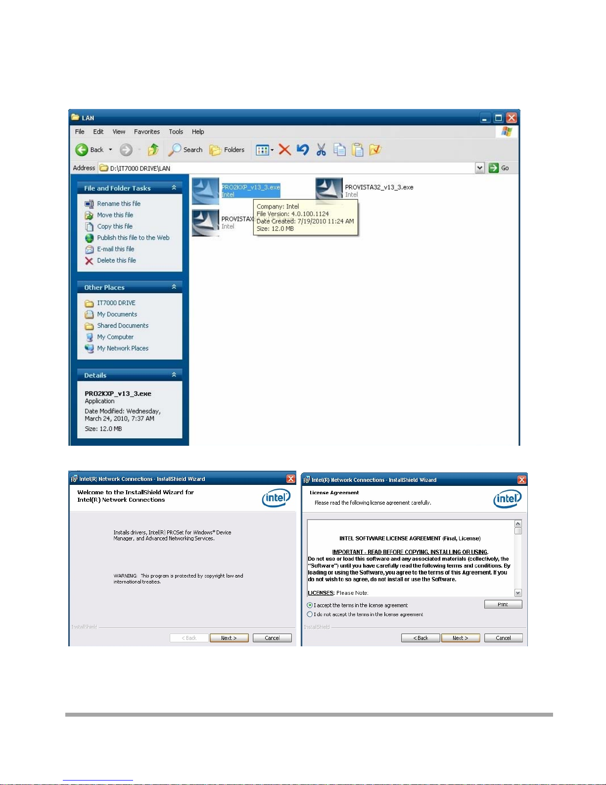
LAN Driver Installation
Select the CD directory to “LAN”
A. Click the “Next” button on the Welcome window

14
B. Click the “Finish” button

15
Audio Driver Installation
Select the CD directory to “Step 4 - Install Realtek AC97 codec Driver”
A. Click “NEXT”

16
B. Click the “Finish” button

17
Touch Kit Touch Driver Installation
Select the CD directory to “TouchKit Driver”
A. Double click “SETUP” on the
My computer window
B. Click the “Next” button on the Welcome
window
C. Click “Next “button on the “Select Type”
window
D. Select “None” and Click “Next”
E. Click “ OK ”
F. Select “Support Multi-Monitor
System” Click “Next”

18
A. Double click “SETUP” on the my computer
window
B. Click the “Next” button on the Welcome
window
G. Install successful and restart your system

19
Four Points Calibration of the touch screen
Always perform the Four Points Calibration of the TouchKit program after your first
installation of the touch screen driver.
A. Select Tools then 4 Points Calibration. B. Press the Green Blink Cross mark.
C. Press OK to continue.
Other manuals for Carisma
1
Table of contents


