Bird Electronic 5010B User manual

INSTRUCTION BOOK
Directional Power Sensor
5010B & 5014
©Copyright 2009 by Bird Electronic Corporation
Instruction Book Part Number 920-5010S Rev. B
Advanced Test Equipment Rentals
www.atecorp.com 800-404-ATEC (2832)
®
E
s
t
a
b
l
i
s
h
e
d
1
9
8
1

0
Safety Precautions
The following are general safety precautions that are
not necessarily related to any specific part or procedure,
and do not necessarily appear elsewhere in this publica-
tion. These precautions must be thoroughly understood
and apply to all phases of operation and maintenance.
WARNING
Keep Away From Live Circuits
Operating Personnel must at all times observe
general safety precautions. Do not replace
components or make adjustments to the inside of the
test equipment with the high voltage supply turned
on. To avoid casualties, always remove power.
WARNING
Shock Hazard
Do not attempt to remove the RF transmission line
while RF power is present.
WARNING
Do Not Service Or Adjust Alone
Under no circumstances should any person reach
into an enclosure for the purpose of service or
adjustment of equipment except in the presence of
someone who is capable of rendering aid.

i
Safety Symbols
Note: Calls attention to supplemental
information.
WARNING
Safety Earth Ground
An uniterruptible earth safety ground must be supplied
from the main power source to test instruments.
Grounding one conductor of a two conductor power cable
is not sufficient protection. Serious injury or death can
occur if this grounding is not properly supplied.
WARNING
Resuscitation
Personnel working with or near high voltages
should be familiar with modern methods of
resuscitation.
WARNING
Warning notes call attention to a procedure, which if
not correctly performed, could result in personal
injury.
CAUTION
Caution notes call attention to a procedure, which if
not correctly performed, could result in damage to
the instrument.

ii
Warning Statements
The following safety warnings appear in the text
where there is danger to operating and maintenance
personnel, and are repeated here for emphasis.
On page 2.
On page 5.
On page 5.
Caution Statements
The following equipment cautions appear in the text
and are repeated here for emphasis.
On page 2.
WARNING
Leaking RF energy is a potential health hazard. DO
NOT connect or disconnect equipment from the
transmission line while RF power is being applied.
Severe burns, electrical shock, or death can occur..
WARNING
Never attempt to connect or disconnect RF equipment
from the transmission line while RF power is being
applied. Leaking RF energy is a potential health hazard
WARNING
RF voltage may be present in RF element socket.
Keep element in socket during operation.
CAUTION
If the element cannot be fully inserted into the
socket, do not force it. This may damage the element.

iii
Safety Statements
USAGE
ANY USE OF THIS INSTRUMENT IN A MANNER
NOT SPECIFIED BY THE MANUFACTURER MAY
IMPAIR THE INSTRUMENT’S SAFETY
PROTECTION.
USO
EL USO DE ESTE INSTRUMENTO DE MANERA
NO ESPECIFICADA POR EL FABRICANTE, PUEDE
ANULAR LA PROTECCIÓN DE SEGURIDAD DEL
INSTRUMENTO.
BENUTZUNG
WIRD DAS GERÄT AUF ANDERE WEISE
VERWENDET ALS VOM HERSTELLER
BESCHRIEBEN, KANN DIE GERÄTESICHERHEIT
BEEINTRÄCHTIGT WERDEN.
UTILISATION
TOUTE UTILISATION DE CET INSTRUMENT QUI
N’EST PAS EXPLICITEMENT PRÉVUE PAR LE
FABRICANT PEUT ENDOMMAGER LE DISPOSITIF
DE PROTECTION DE L’INSTRUMENT.
IMPIEGO
QUALORA QUESTO STRUMENTO VENISSE
UTILIZZATO IN MODO DIVERSO DA COME
SPECIFICATO DAL PRODUTTORE LA PROZIONE
DI SICUREZZA POTREBBE VENIRNE
COMPROMESSA.

iv
SERVICE
SERVICING INSTRUCTIONS ARE FOR USE BY
SERVICE - TRAINED PERSONNEL ONLY. TO AVOID
DANGEROUS ELECTRIC SHOCK, DO NOT PERFORM
ANY SERVICING UNLESS QUALIFIED TO DO SO.
SERVICIO
LAS INSTRUCCIONES DE SERVICIO SON PARA
USO EXCLUSIVO DEL PERSONAL DE SERVICIO
CAPACITADO. PARA EVITAR EL PELIGRO DE
DESCARGAS ELÉCTRICAS, NO REALICE NINGÚN
SERVICIO A MENOS QUE ESTÉ CAPACITADO
PARA HACERIO.
WARTUNG
ANWEISUNGEN FÜR DIE WARTUNG DES
GERÄTES GELTEN NUR FÜR GESCHULTES
FACHPERSONAL. ZUR VERMEIDUNG
GEFÄHRLICHE, ELEKTRISCHE SCHOCKS, SIND
WARTUNGSARBEITEN AUSSCHLIEßLICH VON
QUALIFIZIERTEM SERVICEPERSONAL
DURCHZUFÜHREN.
ENTRENTIEN
L’EMPLOI DES INSTRUCTIONS D’ENTRETIEN
DOIT ÊTRE RÉSERVÉ AU PERSONNEL FORMÉ
AUX OPÉRATIONS D’ENTRETIEN. POUR
PRÉVENIR UN CHOC ÉLECTRIQUE DANGEREUX,
NE PAS EFFECTUER D’ENTRETIEN SI L’ON N’A
PAS ÉTÉ QUALIFIÉ POUR CE FAIRE.

v
ASSISTENZA TECNICA
LE ISTRUZIONI RELATIVE ALL’ASSISTENZA
SONO PREVISTE ESCLUSIVAMENTE PER IL
PERSONALE OPPORTUNAMENTE ADDESTRATO.
PER EVITARE PERICOLOSE SCOSSE ELETTRICHE
NON EFFETTUARRE ALCUNA RIPARAZIONE A
MENO CHE QUALIFICATI A FARLA.

vi
RF VOLTAGE MAY BE PRESENT IN RF ELEMENT
SOCKET - KEEP ELEMENT IN SOCKET DURING
OPERATION.
DE LA TENSION H.F. PEAT ÊTRE PRÉSENTE DANS
LA PRISE DE L'ÉLÉMENT H.F. - CONSERVER
L'ÉLÉMENT DANS LA PRISE LORS DE L'EMPLOI.
HF-SPANNUNG KANN IN DER HF-ELEMENT-
BUCHSE ANSTEHEN - ELEMENT WÄHREND DES
BETRIEBS EINGESTÖPSELT LASSEN.
PUEDE HABER VOLTAJE RF EN EL ENCHUFE DEL
ELEMENTO RF - MANTENGA EL ELEMENTO EN EL
ENCHUFE DURANTE LA OPERACION.
IL PORTAELEMENTO RF PUÒ PRESENTARE
VOLTAGGIO RF - TENERE L'ELEMENTO NELLA
PRESA DURANTE IL FUNZIONAMENTO.

vii
About This Manual
This manual covers the operating and maintenance
instructions for the following models:
Changes to this Manual
We have made every effort to ensure this manual is
accurate. If you discover any errors, or if you have sug-
gestions for improving this manual, please send your
comments to our Solon, Ohio factory. This manual
may be periodically updated. When inquiring about
updates to this manual refer to the part number and
revision on the title page.
Literature Contents
Chapter Layout
Introduction —Describes the features of the Direc-
tional Power Sensor and Element Types.
Installation —Describes how to connection and install
the Directional Power Sensor into the system that is
being monitored.
Specifications - Describes the basic information, set-
tings, and ranges of the Digital Power Sensor.
5010B 5014

viii

ix
Table of Contents
Safety Precautions. . . . . . . . . . . . . . . . . . . . . . . . . 0
Safety Symbols. . . . . . . . . . . . . . . . . . . . . . . . . . . . . i
Warning Statements . . . . . . . . . . . . . . . . . . . . . . . ii
Caution Statements. . . . . . . . . . . . . . . . . . . . . . . . ii
Safety Statements . . . . . . . . . . . . . . . . . . . . . . . . . iii
About This Manual. . . . . . . . . . . . . . . . . . . . . . . . vii
Changes to this Manual . . . . . . . . . . . . . . . . . . . vii
Literature Contents. . . . . . . . . . . . . . . . . . . . . . . vii
Chapter Layout . . . . . . . . . . . . . . . . . . . . . . . .vii
Chapter 1 Introduction . . . . . . . . . . . . . . . . . . . . 1
Description . . . . . . . . . . . . . . . . . . . . . . . . . . . . . . . 1
Element Types . . . . . . . . . . . . . . . . . . . . . . . . . . . . 1
43 Type Elements . . . . . . . . . . . . . . . . . . . . . . . 1
APM/DPM Elements . . . . . . . . . . . . . . . . . . . . . 2
Element Orientation . . . . . . . . . . . . . . . . . . . . . . . 2
Element Contact Alignment . . . . . . . . . . . . . . . 3
Chapter 2 Installation . . . . . . . . . . . . . . . . . . . . . . 5
Connecting the Directional
Power Sensor (DPS) . . . . . . . . . . . . . . . . . . . . . . 5
Chapter 3 Specifications . . . . . . . . . . . . . . . . . . . . 7
5010B Specifications . . . . . . . . . . . . . . . . . . . . . . . 7
5014 Specifications . . . . . . . . . . . . . . . . . . . . . . . 11
Limited Warranty. . . . . . . . . . . . . . . . . . . . . . . . . 15

x

1
Chapter 1 Introduction
Description
The DPS series sensors utilize elements in order to
make power measurements. Each element has an arrow
on it that represents the direction in which it measures
power. The elements ignore power in the opposite
direction with a directivity of at least 25 dB. The DPS
series can make power measurements using either 43
type or APM/DPM elements, and the readings available
vary, based on which elements are being used.
Since the DPS uses two elements, it can measure the
quality of the system by comparing the forward and the
reflected power. This is usually presented in the form
of VSWR (voltage standing wave ratio) or Return Loss.
Element Types
43 Type Elements
The 43 type elements are normally used to measure
peak power. These elements can measure the peak
power of a system with an accuracy of +/-8% of full
scale as long as the signal meets the following
requirements:
zAt least 15 pps (pulses per second)
zMinimum pulse width of 15 µs (800 ns if
frequency is greater than 100 MHz)
zMinimum Duty Cycle of 0.01%

2
In addition, 43 type elements can be used to measure
average power in signals with a peak-to-average ratio
close to 1, like a CW or FM signals. In these cases, the
average power is measured with an accuracy of +/- 5%
of full scale.
APM/DPM Elements
The APM/DPM elements are used to measure true
average power. True average power means the sensor
provides equivalent heating power of the signal,
regardless of modulation or number of carriers. These
elements can measure average power with an
accuracy of +/-5% of reading from full scale down to
2.5% of full scale.
Note: The equivalent heating power is
dependent on the duty cycle of a signal. If a sys-
tem puts out 50 watts with a 50% duty cycle, the
APM/DPM elements will measure 25 watts.
Element Orientation
The forward element and the reflected element must
be of the same series (APM or 43). The power rating
of the forward element must be 10x the power rating
of the reverse element.
WARNING
Leaking RF energy is a potential health hazard. DO
NOT connect or disconnect equipment from the
transmission line while RF power is being applied.
Severe burns, electrical shock, or death can occur.
3
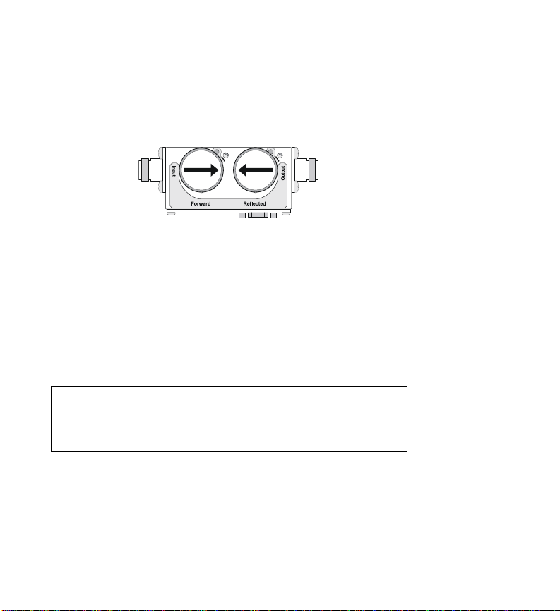
Insert the forward element into the forward socket
with its arrow pointing in the direction of forward
power. Insert the reflected element into the reflected
socket with its arrow pointing in the direction of
reverse power.
Element Contact Alignment
Continuous insertion or rotation of the element might
cause a slight change in the position of the contact
spring in the element socket. If the contact spring
changes position, erratic power readings may be
experienced.
The position of the contact spring may be adjusted
with a small screwdriver to reestablish contact.
Perform the following steps to adjust the contact spring:
1. Using a small flat head screwdriver, place the flat
side of the screwdriver behind the contact bar as
indicated and bend the contact bar so that the con-
tact rests in the center of the slot adjacent to the
element socket.
CAUTION
If the element cannot be fully inserted into the
socket, do not force it. This may damage the
element.

4
2. After centering the contact, bend the contact bar
slightly toward the center of the element socket
bore, so that the profile of the element contact is
visible when viewing the element socket from the
top of the socket bore.
Note: If the contact is accidently moved too
far, the element will not slide into the socket.
Move the contact back into the recessed area
and repeat the process.
Output
Reflected
Forward
Input
Output

5
Chapter 2 Installation
Connecting the Directional Power Sensor (DPS)
1. Do one of the following:
zTo connect to a Digital Power Meter:
zFor Models 5010 and 5010B:
Connect the Bird DPS to the “Sensor”
serial port on the DPM using the sensor
cable provided.
WARNING
Never attempt to connect or disconnect RF
equipment from the transmission line while RF
power is being applied.
Leaking RF energy is a potential health hazard.
WARNING
RF voltage may be present in RF element socket.
Keep element in socket during operation.

6
zFor Models 5014:
Connect the Bird DPS to the “Sensor” USB
port on the DPM using the sensor cable
provided.
zTo connect to a PC with VPM2 software (5014
ONLY):
zConnect the Bird DPS to the a USB port on
the PC using the sensor cable provided.
2. Connect the DPS to the RF line so that the arrow
on the sensor points towards the load, see “Ele-
ment Orientation” on page 2.
Note: The arrow on the forward element
should point towards the load.
Note: The arrow on the reflected element
should point towards the source.
Note: Both elements must be either APM/
DPM or 43 types, do not mix elements.
3. Set the power on the DPM to the forward ele-
ment’s power rating.

7
Chapter 3 Specifications
5010B Specifications
Sensor Type Thruline two-element line section
Elements
5010B
5010T
Select two elements from the
same series, with RFL power 1/
10 of FWD power.
APM or 43 series elements
APM elements only
Frequency Rangea2 – 3600 MHz
Average Power Measurement, APM Elements, Forward or
Reflected Direction
PowerMeasurement
Rangea 0.1 W to 1 kW
Uncertaintyb± 5% of reading (95% c.l.)
Peak/Average Ratio,
Max 10 dB
Detector Response
(5010T only) 230 ms
Average Power Measurement, APM Elements, Forward or
Reflected Direction
PowerMeasurement
Range 0.1 W to 10 kW

8
PowerMeasurement
Uncertainty ± 5% of full scale average power
(95% c.l.)
Peak Power Measurement, 43 Elements only, Forward
direction only
Pulse Width, Min
2 – 25 MHz
25 – 100 MHz
> 100 MHz
15 µs
1.5 µs
800 ns
Rep. Rate, Min 15 pps
Duty Cycle, Min 1 x 10⁻⁴
Uncertaintyb± 8% of full-scale peak envelope
power (95% c.l.)
Match Measurement
Match Range
Return Loss
Rho (ρ)
VSWR
0 to 20 dB
0.1 to 1
1.22 to 99.99
Uncertainty Twice the Avg Power Uncertainty
(Calculated from forward and
reflected uncertainty)
Settling Time, Max 2.5 seconds
Impedance, Nominal 50 ohms
Insertion Loss, Max 0.05 dB up to 1 GHz
Input VSWR, Max. 1.05:1 up to 1 GHz
Directivity, Typicala 30 dB
RF Connectors QC Type (N(F) normally supplied)
Power Supply From host instrument via cable
This manual suits for next models
1
Table of contents


