Page 2 of 5 4/15/2010 921-4300-400 Rev B
Installing the Model 4300-400 Modification Kit
1. Remove the four No. 8 Phillips flat head screws on the sides of the Model 43.
2. Pull the rear cover straight out to expose the interior.
3. Loosen and remove the two outer nuts, cable lugs, and washers from the studs on the meter.
4. Unwind the cable from the meter.
Note: Do not loosen or remove the nuts holding the studs to the meter case.
5. Remove the line section from the housing by removing the two No. 10 Phillips oval head screws from the
front of the Model 43.
6. Slide the line section backwards out of the housing.
7. Reroute the cable from the line section connector to run up between the line section and the housing.
Note: Recoil excess cable around the meter.
8. Replace the line section and secure it with the two No. 10 Phillips®oval head screws.
Note: Do not reconnect the cable to the meter.
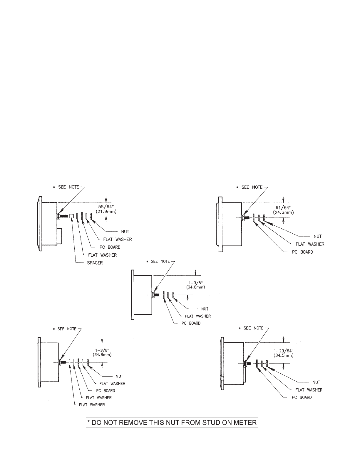
9. Refer to Figure 1 on page 3 to determine which type of meter is used in the Model 43.
Note: The type of meter will determine what hardware (washers and spacers) to place on the meter
studs to assure a properly aligned PC board in the installation.
10. Install the hardware and the PC board on the studs per the appropriate drawing.
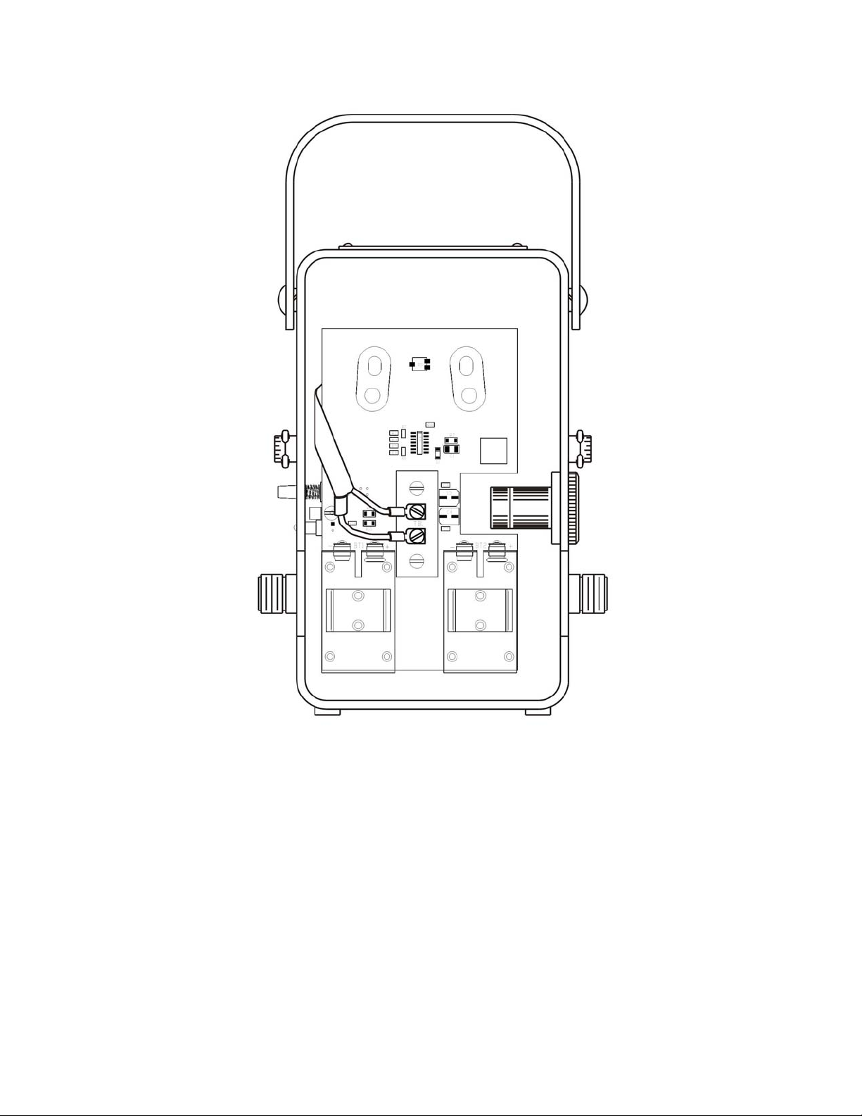
11. Align the board to locate the push switch and LED assembly in the empty hole on the side of the case.
Note: Use the upper or lower holes in the boards that match the studs.
12. Bring the DC cable with terminals along the left of the case.
13. Place the washers and nuts over the studs, but do not tighten yet.
Note: In some Model 43 Wattmeters, slight variations in the housing dimensions may affect the align-
ment of the ON-OFF switch/LED assembly in the side hole of the case. These variations affect the hole
location in the front-to-back dimension. To compensate for the variations, add or subtract flat washers,
as installed in Step 13, to align the switch/LED assembly in the side hole.
14. Install the plug insert (with the label) over the switch cap and LED.
Note: Be sure to line it up with the PC board mounting block.
15. Install the 4-40 phillips head screw through the plug, matching it up with the mounting block, and then
tighten.
16. Install the DC cable lugs to the terminal board (TB1) screw terminals.
Note: The black wire connects to negative (-) and the center conductor of the cable assembly connects to
the terminal marked positive (+).
Note: Some Model 43 Wattmeters were manufactured using terminal lugs on the meter cable that are
slightly wider than the lugs presently being used. These wider lugs will not fit between the barriers on
the terminal board (TB1) mounted on the PC board. Use diagonal cutters or side cutters to trim about
1/32 inch off each side of the lug so that it will fit between the barriers of the terminal board.
17. Tighten the meter stud nuts.
18. Connect the batteries by pushing on the battery connectors.
19. Perform a calibration check.
Note: Refer to the calibration instructions.
Qty Description Part Number
1 PC Board 4300A402
2 Brass Spacers 4300-411
2 No. 8 Brass Washers --
2 9 V Alkaline Battery 5-1375
1 4-40 x 1/4 inch Phillips
Head Screw --
1 Plug/Insert, 4300-407 with pn 4300-408 label attached