BISOL BIPV User manual

The sunny side of life!
EN
General Information
Installation Manual
BISOL BIPV MODULES
AND MOUNTING STRUCTURE

2Installation Manual: BIPV Modules
We want to congratulate you for purchasing BISOL BIPV solar modules and express our most sincere gratitude for using products that
are high energy ecient and designed for long-term high-performance use. It is our pleasure and delight to know that we have been
able to full your expectations with our high-quality materials processed on state-of-the-art automated production line.
We are proud of our products, and we are proud of you as our BISOL ambassador.
BISOL Team
Before starting the installation of BISOL BIPV solar modules, carefully read this entire installation manual.
This manual contains important information about safety, installation, wiring, operating, maintenance and
similar.
If any further information is necessary, please consult your module dealer or the manufacturer directly.
Failure to follow these instructions may result in material damage and can in worst case jeopardize life
safety and health.
Store this manual in an easy reachable place.
THANK YOU!
!

4
Installation Manual: BIPV Modules
3Installation Manual: BIPV Modules
5 INSTALLATION ..................................................................................................................................................... 29
5.1 Checking the Requirements ........................................................................................................................... 29
5.1.1 Roof Plan and String Plan .............................................................................................................................. 29
5.1.2 Limit of Application....................................................................................................................................... 29
5.1.3 Safety at Work .............................................................................................................................................. 29
5.1.4 Checking the Content of the Shipment............................................................................................................ 30
5.2 Tools .................................................................................................................................................................. 30
5.3 Mounting .......................................................................................................................................................... 30
5.3.1 Preparing the Roof........................................................................................................................................ 30
5.3.2 Calibrating and Placing the Substructure........................................................................................................ 32
5.3.2.1 Mounting the Solrif ® Battens....................................................................................................................... 33
5.3.3 Determining the Reference Point and Perpendicularity of the PV Array ............................................................ 35
5.3.4 Mounting the Lead Flashing........................................................................................................................... 36
5.3.5 Laying Cable Conduits, Connection Cables and Cable Strings ............................................................................ 37
5.3.6 Marking the Horizontal Positions of the Mounting Clamps Prole..................................................................... 38
5.3.7 Laying the Bottom Row of Modules ................................................................................................................ 39
5.3.8 Laying the Remaining PV Array ...................................................................................................................... 44
5.3.9 Top of the Array............................................................................................................................................. 50
5.3.10 Finishing Process......................................................................................................................................... 53
6 MAINTENANCE....................................................................................................................................................... 56
6.1 Maintenance Plan............................................................................................................................................ 56
6.2 Replacing Modules........................................................................................................................................... 57
7 DEINSTALLATION AND DISPOSAL...................................................................................................................... 57
8 ADDITIONAL INSTRUCTIONS.............................................................................................................................. 58
8.1 Rules for Mounting Battens............................................................................................................................ 58
9 FURTHER INFORMATION..................................................................................................................................... 59
TABLE OF CONTENTS
1 GENERAL INFORMATION .......................................................................................................................................6
1.1 Information on this Manual..............................................................................................................................6
1.2 Exclusion of Liability..........................................................................................................................................7
1.3 Guarantee Conditions........................................................................................................................................8
1.4 Customer Service and Product Monitoring .....................................................................................................8
2 SAFETY REQUIREMENTS........................................................................................................................................8
2.1 Introduction .......................................................................................................................................................8
2.2 Responsibility.....................................................................................................................................................8
3 INSTALLATION MANUAL........................................................................................................................................9
DESCRIPTION OF THE BISOL BIPV MODULES WITH SOLRIF® INROOF MOUNTING SYSTEM................................9
3.1 BISOL BIPV Modules with Solrif® In-roof Mounting System Overview.........................................................9
3.2 Components....................................................................................................................................................... 10
3.2.1 BISOL BIPV Module with Solrif® Frame............................................................................................................ 11
3.2.2 Dimension of PV Array and Module Mounting Pitches...................................................................................... 12
3.2.3 Substructure................................................................................................................................................. 15
3.2.4 Mounting Clamps.......................................................................................................................................... 16
3.2. Flashing Proles ............................................................................................................................................. 18
3.2.6 Side Flashings ............................................................................................................................................... 18
3.2.7 Bottom of PV-Array: Lead Flashing, Wedge Plank, Sealing Tape Strip ................................................................ 20
3.2.7.1 Lead Flashing............................................................................................................................................. 21
3.2.7.2 Wedge Plank .............................................................................................................................................. 21
3.2.7.3 Sealing Tape Strip ...................................................................................................................................... 23
3.2.8 Connection Cables, Cable Strings .................................................................................................................... 23
3.2.9 Grounding and Lightning Protection .............................................................................................................. 24
3.2.10 Mounting Screws for Battens........................................................................................................................ 25
3.2.11 Other Accessories......................................................................................................................................... 25
3.2.11.1 Fixing for Flashing.................................................................................................................................... 25
3.2.11.2 Protective Proles .................................................................................................................................... 26
3.2.11.3 L-Section to Support the Bottom Row of Mounting Clamps................................................................................ 26
3.3 Technical Data/Limit of Application............................................................................................................... 27
4 TRANSPORTATION................................................................................................................................................. 28
4.1 Transportation in Packaging .......................................................................................................................... 28
4.2 Transportation of Individual Modules........................................................................................................... 28

6
Installation Manual: BIPV Modules
5Installation Manual: BIPV Modules
1 GENERAL INFORMATION
Notice
BISOL BIPV INSTALLATION MANUAL is the summary of installation manual with title:
Solar Energy Systems by Schweizer: Installation Manual – Photovoltaic In-Roof Mounting
System Solrif®.
All information provided (including pictorial material) is owned by the Ernst Schweizer AG.
BISOL BIPV INSTALLATION MANUAL is specically modied for BISOL BIPV modules and
mounting structures owners only.
1.1 Information on this Manual
This manual describes the procedure for the in-roof mounting of BISOL BIPV modules as well as for replacing BISOL BIPV modules
with Solrif® in-roof mounting system. With in-roof mounting, the PV array substitutes any existing tile roong. However, tile
roong remains around the PV array. In addition, this manual provides instructions on the maintenance of BISOL BIPV modules
with Solrif® in-roof mounting system and their disposal.
Supplementary Documents
Delivery note with article numbers and description of all components delivered.
Limit
• The installation of full-roof PV systems (the roof is covered completely with photovoltaic modules or dum my modules, no
tiles are left on the roof) is possible, but is not the subject of this installation manual.
• For connection of the PV array to the inverter, please refer to the inverter supplier’s documentation.
This manual is intended for craftspeople who have completed their vocational training in the roong trade. Furthermore, the
craftsman must also have acquired either an additional qualication for the installation of photovoltaic systems or have many
years of experience in the installation of photovoltaic systems. With regard to adhering to maintenance procedures, this manual
is also directed at the operator of the photo voltaic system.
Before carrying out any work, the implementing or supervising person must:
• Read this manual carefully and understand it, or clarify any ambiguity with the system’s planners.
• Instruct assisting personnel according to this manual and supervise them during the entire work process.
The installation company must:
• Keep this manual to hand during the entire work procedure on the building site.
• After the installation work has been completed: hand over this manual to the system operator.
The system operator must:
• Store this manual and the delivery note with the rest of the system documentation.
• Observe the instructions on system maintenance.
• Make this manual and any further relevant documentation available to the specialist personnel who have been commissioned
to carry out the maintenance, repair or deinstallation work and enclose them with the documentation for the photovoltaic
system again after the work has been completed.
The seller of the system or of the building on which it is installed must:
• Pass on this manual to the new operator as part of the system documentation.
Further applicable documents, regulations and provisions
• Apart from this manual, please observe the module pitch plan and the string plan, the relevant safety regu lations, particularly
those for working on a roof and for handling electrical currents, as well as the documentation for the other components in
the photovoltaic system.
• In the event of discrepancies or other ambiguity, clarify these through the system’s planners.
Diagrams in this manual are intended to aid fundamental understanding and show the example of a 3x3-array. The
implementation for the actual design must be analogous to this example portrayed here.
1.2 Exclusion of Liability
BISOL Production Ltd. as a manufacturer of BISOL BIPV photovoltaic modules takes no responsibility for the design solutions of
individual designers nor for Solrif® system solutions, which as such are a product of Ernst Schweizer AG, all in connection to the
installation of photovoltaic modules with Solrif® system.
The information and safety instructions in this manual have been compiled taking into account the currently applicable norms,
guidelines and regulations, the latest technology and the long years of experience gathered by BISOL Production Ltd. and Ernst
Schweizer AG.
The shipment contents, or the design of the system, can deviate from the descriptions and diagrams specied in this manual
because of optional items ordered, manufacture of customised designs or the latest technological changes.
This manual’s publication date shall apply. BISOL Production Ltd. reserves the right to update this manual in the light of technical
changes to the system as part of further development to improve performance characteristics and safety. The most recent
version of this manual is published on ocial website www.bisol.com.
BISOL Production Ltd. accepts no liability for damages and accidents that may arise in particular from the following causes:
• Inappropriate use of the mounting system
• Non-observance of the information and instructions in this manual
• Work carried out on or with the system by non-qualied or unauthorised personnel
• Mounting of non-original spare parts
• Unauthorised modications

8
Installation Manual: BIPV Modules
7Installation Manual: BIPV Modules
1.4 Customer Service and Product Monitoring
For problems and questions that cannot be solved with the aid of this manual and/or on consultation with the planner, as well
as for technical information:
• Please contact the customer service of the BISOL Production Ltd or of Ernst Schweizer AG. Above and beyond customer
service, BISOL Production Ltd is interested in experiences that arise from dealing with the system with the objective of
constantly improving the system.
• In the event of problems when dealing with the system, interruptions in operation and any errors that occur, please contact
BISOL Production Ltd using the contact data in the footer.
2 SAFETY REQUIREMENTS
2.1 Introduction
Installation of the device may only be carried out by authorized personnel and industry experts who are familiar with all the latest
international and local guidelines for the installation of PV products. Non-observance of the safety requirements instructions
and safety and warning notices specied in local legislation and guidelines can lead to considerable dangers.
2.2 Responsibility
As customer/operator:
Only commission specialist rms which oer guarantees for the professional and safety-oriented work execution with the
planning of the system and the execution of the installation, maintenance, repair and deinstallation work.
As employer of the rm executing the work:
Ensure that all work is carried out or supervised by suciently qualied specialist personnel, roong jobs by roofers, AC/DC
cabling by electricians. Ensure that at least two persons are present on the construction site at all times while work is being
conducted.
Ensure that instructed personnel/assistant personnel were instructed suciently on safety-oriented work on the roof and is
supervised during the entire work process. Also observe the country-specic accident prevention regulations of the respective
trade associations (in Germany: BGV A1 – Principles of Prevention BGV A3 – Electrical Plant and Equipment, BGV C22 –
Construction Work).
Ensure collective protection (scaoldings, roof guard rails) in accordance with the current regulations (installation of photovoltaic
systems on roofs is only permissible with collective protection).
Ensure that all personnel that carries out work on the photovoltaic system or supervises such work has read and understood this
manual, that assistant personnel were instructed suciently and is supervised during the entire work process.
1.3 Guarantee Conditions
BISOL BIPV photovoltaic modules are subject to the Standard Limited Guarantee (SLG) terms and conditions, which are published
on the ocial website www.bisol.com.
Supply your personnel with personal protective equipment (PPE) in accordance with the current regulations for roof work and
enforce the correct use of PPE. Before installing the system, ensure that the roof substructure (rafters, roof battens) corresponds
to national regulations in terms of both quality and load-bearing capacity.
As the person executing or supervising the work:
Only tread onto the roof if the conditions for working safely are fullled. Instruct assisting personnel on all safety-relevant
aspects and supervise them during the entire work process.
The employer in the rm executing the work must ensure that the requisite safety measures have been taken to prevent falls.
The system operator must:
Observe the maintenance intervals stipulated in this manual.
For other information on safety regulations, you can also see:
Installation Manual – General Information at www.ernstschweizer.ch.
3 INSTALLATION MANUAL
DESCRIPTION OF THE BISOL BIPV MODULES WITH SOLRIF® INROOF MOUNTING SYSTEM
3.1 BISOL BIPV Modules with Solrif®
In-roof Mounting System Overview
Figure 1: BISOL BIPV modules with Solrif® in-roof mounting system overview

10
Installation Manual: BIPV Modules
9Installation Manual: BIPV Modules
General Components Overview
1Lead flashing, wedge plank, sealing tape strip
2Fixing for flashing
3Mounting Clamp (Profile/Glass)
4Wood screws with pan head 4.5 × 35
5Flashing side left
6Flashing profile left
7Solrif® batten 120×30 mm²
8Tiling battens
9Flashing side top left
10 Flashing top left
11 BISOL BIPV with Solrif® frame
12 Protective profile
13 Flashing top middle
Notice
Measurements that are taken from the left-hand edge of the PV array towards the right, meaning
horizontally, parallel to the eaves or to the roof ridge, will henceforth be referred to as “width.”
Measurements that are taken from the eaves towards the roof ridge, parallel to the verge, will henceforth
be referred to as“height.”Measurements that are taken perpendicular to the roof surface will be referred
to as “thickness.” The largest measurement of a component before installation will be referred to as
“length” irrespective of its orientation after installation. These descriptions can deviate from those in
your supplier’s data sheet, for example, the measurement of the longer side of the module can be
described as “length” and that of the shorter side as “width,” irrespective of the module’s orientation
after installation.
3.2 Components
3.2.1 BISOL BIPV Module with Solrif® Frame
Figure 2: BISOL BIPV module with Solrif® frame overview
BISL BIPV Components Overview
1BISOL BIPV laminate
2Solrif® frame profiles
3Backsheet or glass
4Connection cables with connectors
5Junction box
The frames of modules placed side by side interlock. The modules that are installed above overlap the modules below them
(like roof tiles). A rubber lip in the upper prole seals between the two modules. Thus the photovoltaic modules form the water-
proong layer on the roof. Hence for roof slopes > 10°, rainproof integration into the roong is possible in accordance to ZVDH
regulations (Central German Roong Industry Association).
• Only use a BISOL BIPV module within one PV array.

12
Installation Manual: BIPV Modules
11 Installation Manual: BIPV Modules
3.2.2 Dimension of PV Array and Module Mounting Pitches
Figure 3: Layout of the module pitch (3 modules BISOL BIPV’s inserted)
Figure 4: Details
Figure 5: Horizontal cross-section
Figure 6: Vertical cross-section

14
Installation Manual: BIPV Modules
13 Installation Manual: BIPV Modules
General Components Overview
1Fkashing side left
2Flashing profile left
3BISOL BIPV module
4Flashing profile right
5Flashing side right
6Wedge plank
7Mounting Clamp Profile
8Flashing top
LBWidth of the laminate
LHHeight of the laminate
MBWidth of a single framed module = L_B + 50
MHHeight of a single framed module = L_H + 32
Rhor
Rhor Horizontal module mounting pitch (distance of any reference point on the module to the same point on the module
mounted beside it to the right or left) = MB– 18
Rver
Rver Vertical module mounting pitch (distance of any reference point on the module to the same point on the module
mounted above or below it) = MH– 32
Nhor Nhor Number of modules laid out side by side in the PV array
Nver Nver Number of modules laid out above each other in the PV array
BGR Width of the PV array between the ashing sides = (Nhor × Rhor) + 42
BGL BGL Width of the PV array including the ashing sides = (Nhor × Rhor) + 284
HG
HG Height of the PV array between the lower edge of the bottom mounting clamp and the upper edge of the top mounting
clamp = (Nver × Rver) + 104
HGB
HGB Height of the PV array between the lower edge of the bottom mounting clamp and the upper edge of the ashing tops
= (Nver × Rver) + 283
3.2.3 Substructure
Solrif® battens measuring 120 mm × 30 mm are used as a substructure, which are screwed onto the existing roof construction
instead of or in-between the roof battens to which the tiles were attached. Minimum requirements for wood quality: Strength
category C24.
Notice
Plan an extra 10 % for cutting losses compared to the batten plan. In addition, keep some spare wood to
hand to equalize out any unevenness in the roof construction or to be able to implement connections
or linings. A wedge plank is necessary for the bottom gutter of the PV array, see Chapter „Wedge Plank“.
The bottom row of Solrif® battens must extend beyond the ashing sides by at least 150 mm respectively as an overlay for the
lead ashing, i. e. the length of the bottom row of Solrif® battens must be at least BGL + 300 mm.
All other rows of Solrif® battens must extend beyond the ashing sides by at least 50 mm respectively, i. e. the length of the
other rows of Solrif® battens must be at least BGL + 100 mm respectively.
Figure 7: Substructure

16
Installation Manual: BIPV Modules
15 Installation Manual: BIPV Modules
3.2.4 Mounting Clamps
BISOL BIPV module with Solrif® frame are attached to the substructure with mounting clamps. There are three dierent types
of clamps:
Figure 8: Mounting clamps
Art. No. Application
1
Mounting Clamp Profile
- raw, 1.4310
- black/browned, 1.4310
- raw seawater-resistant, 1.4404
13318
06497
13995
Fastens overlapping modules in the area of the profiles
left/right or flash ing tops; always required
2
Mounting Clamp Glass with protective shrink tubing
- raw, 1.4310
- black/browned, 1.4310
- raw seawater-resistant, 1.4404
13319
06500
13996
Fastens overlapping modules in the area of the open
glass edge; number according to structural analysis
requirements
3
Mounting Clamp Top
- raw, 1.4310
- raw seawater-resistant, 1.4404
33954
13997 For fastening the top row of modules when not using
regular flashings top
4
Wood screw with pan head 4.5×35 SST, with general
building inspectorate approval ETA/DIBt
(countersunk bolts may not be used)
61831
Notice
Danger of confusion!
Please be aware that the dierent types of clamps must be used positioned and in quantities as required
according to the roof plan.
Roof plan design needs to be done with PV planning software SPT (proSOLRIF design software SPT at
www.ernstschweizer.ch for calculating the number of mounting clamps required per module.)
Figure 9: Mounting clamps mounted
1Mounting clamp prole mounted with the ashing tops
2Mounting clamp prole for securing the module overlap or the overlap with ashing proles
3Mounting clamp glass for securing the bottom module edge
18
Installation Manual: BIPV Modules
17 Installation Manual: BIPV Modules
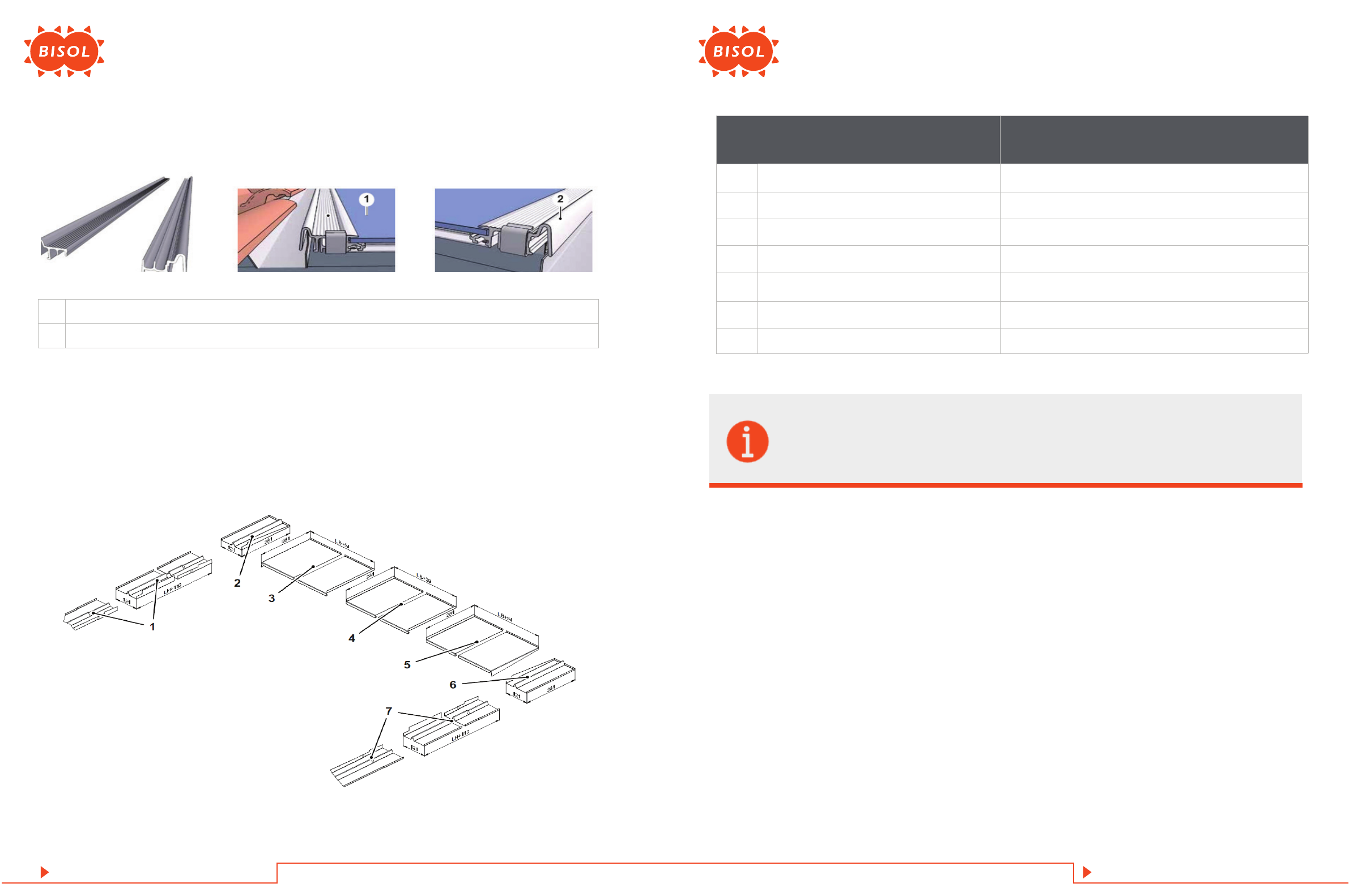
3.2. Flashing Proles
Figure 10: Flashing proles
1Flashing prole left
2Flashing prole right
3.2.6 Side Flashings
The ashing sides create a link between ashing proles and roof tiles. The ashing tops ensure a transition between the top
module edge and the row of tiles that lies above it. They are designed in such a way that they are suitable for many conventional
types of roof tiles. In the event of other requirements (e. g. tiling bat tens and Solrif® battens at dierent levels, special types of
tiles, like slate, etc.) please contact BISOL Production Ltd and Ernst Schweizer AG.
Figure 11: Side ashings
Measurements height × width
LH= laminate height, LB= laminate width
1Flashing side left (LH+110) × 121
2Flashing side top left 281 × 121
3Flashing top left 281 × (LB + 54)
4Flashing top middle 281 × (LB + 32)
5Flashing top right 281 × (LB + 54)
6Flashing side top right 281 × 121
7Flashing side right (LH+110) × 121
Notice
When using side ashings other than the original Solrif® side ashings, it must be checked whether
galvanic separation is necessary.

20
Installation Manual: BIPV Modules
19 Installation Manual: BIPV Modules
1Roof tile
2Lead flashing
3Wedge plank
4Mounting clamps
5Sealing tape strip
6BISOL BIPV module with Solrif® frame
7Solrif® batten
DKu Thickness of the wedge plank at the bottom
HKHeight of the wedge plank
3.2.7 Bottom of PV-Array: Lead Flashing, Wedge Plank, Sealing Tape Strip
Figure 12: Bottom gutter
The BISOL BIPV module with Solrif® frame can be mounted either down to the eaves or with tile roong between PV array and
eaves. Observe the tech note about the application limits (snow loads) in the instruction sheet under customer login at www.
ernstschweizer.ch.
When tile roong is used between PV array and eaves, the transition should be executed using lead ashing and wedge plank.
3.2.7.1 Lead Flashing
For the transition from the bottom edge of the array to the tiles, lead ashing is used as is customary for other roof inserts, for
example skylights (lead foil roll 300 mm or black aluminium Mage Flex ashing tape.
280 mm or 450 mm available as accessories, roll length 5 m or 7.5 m). The required height of the lead ash ing depends on the
roof slope and the tile arch and must be determined in combination with the height of the wedge plank, see Chapter „Wedge
Plank“.
Notice
If the lead ashing is to be comprised of several sections of Mage Flex ashing tape, the sections must
overlap by at least 100 mm.
3.2.7.2 Wedge Plank
The wedge plank is mounted underneath the bottom Solrif® batten. It supports the lead ashing, ensuring that no trough forms
in the lead ashing and thus no water can remain there.
Minimum requirements for wood quality: Strength category C24
Figure 13: Excess height

22
Installation Manual: BIPV Modules
21 Installation Manual: BIPV Modules
3.2.7.3 Sealing Tape Strip
Roof slope Excess height ~20 mm Excess height ~40 mm
HKDKu HKDKu
10° 145 mm 50 mm 300 mm 70 mm
15° 75 mm 45 mm 170 mm 65 mm
20° 45 mm 45 mm 110 mm 65 mm
25° 30 mm 40 mm 80 mm 60 mm
30° 20 mm 40 mm 60 mm 60 mm
35° 10 mm 40 mm 45 mm 60 mm
40° 10 mm 35 mm 30 mm 55 mm
Figure 14: Measurements of the wedge plank
The length of the wedge plank corresponds to the width of the PV array including the ashing sides (BGL).
The sealing tape strip is mounted onto the lead ashing to close the gap underneath the bottom row of clamps against small
animals.
Figure 15: Sealing tape strip
3.2.8 Connection Cables, Cable Strings
Use connection cables and cable strings which full the following requirements:
• Made of exible copper wire.
• Double insulation, suitable for in-roof installation, meets protection class II (SCII) and IEC 61730.
• Heat resistant up to at least 90 °C.
• Has dimensions in accordance with the regulations at the place of installation.
• Follow the directions for the division of the PV array into strings and the resulting position of connection cables and cable
strings in the module pitch plan or string plan which was drawn up by the system planner.
• When the modules are arranged in a series connection, ensure that the maximum permissible system voltage is not exceeded.
• When the modules are arranged in a parallel connection, ensure that every row is fused with its own fuse.
• Observe the instructions of the module manufacturer and of the system planner.
1Sealing tape strip

24
Installation Manual: BIPV Modules
23 Installation Manual: BIPV Modules
3.2.10 Mounting Screws for Battens
To mount the Solrif® battens to the counter battens, 2 wood screws with general building inspectorate approval in accordance
with roong standards are required for each intersection of a Solrif® batten and counter batten:
3.2.9 Grounding and Lightning Protection
Notice
The national and local requirements regarding grounding and lightning protection must be observed.
A photovoltaic system does not aect whether lightning protection is necessary or not, i. e. a roof without a photovoltaic system
which does not have to be tted with lightning protection does not need lightning protec tion even with a photovoltaic system.
If lightning protection exists, the photovoltaic system must be integrated into the lightning protection pursuant to the local
regulations. You will nd further details in the tech note under your customer login at www.ernstschweizer.ch.
Figure 16: Drilling work for grounding
1Flashing top
2Module
3Cable strings
4Grounding cables within a grounding string
5Grounding cables between array and household fuse box
6Holes (Φ 3.3 mm) for grounding (view onto top module edge)
Diameter Length 5 mm
Permissible shape of head Thickness of the counter batten + 60 mm Countersunk
3.2.11 Other Accessories
Fixing for ashing is used to mount the side ashing onto the Solrif® battens or tiling battens.
3.2.11.1 Fixing for Flashing
Figure 17: Fixing for ashing on ashing sidesgrounding
1Fixing for flashing
2Clout nail 2.5 × 25 mm

26
Installation Manual: BIPV Modules
25 Installation Manual: BIPV Modules
Roof plan design needs to be done with PV planning software SPT (proSOLRIF design software SPT at www.ernstschweizer.ch
for calculating the number of mounting clamps required per module).
3.2.11.2 Protective Proles
Protective proles are used to connect ashing tops, see Chapter „Side Flashings“.
Figure 18: Protective prole (view onto top edge of array)
1Protective profile
3.2.11.3 L-Section to Support the Bottom Row of Mounting Clamps
Figure 19: L-section
1L-section
In elevated snow load conditions (> 2,400 Pa) the bottom row of mounting clamps must be supported (to be provided by the
customer: e. g. using a 16 mm aluminium L-section, a piece of wood or similar).
3.3 Technical Data/Limit of Application
Measurements/Weight of the Modules see the module manufacturer's data sheet
Max. snow load
5,400 N/m² **, structural design must be observed
(proSOLRIF design software at www.ernstschweizer.ch for
calculating the number of mounting clamps required per
module.)
Max. wind load (suction)
2,400 N/m² **, structural design must be observed
(proSOLRIF design software at www.ernstschweizer.ch for
calculating the number of mounting clamps required per
module.)
Substructure
Requirements according to the effects (wind and snow loads)
on the supporting structures and taking into account the
planned implementation of the PV array (Germany: DIN 1055-
4 Wind loads, DIN 1055-5 – Snow and ice loads, EN 1991-
1-3 – Snow loads (Eurocode 1), EN 1991-1-4 – Wind loads
(Eurocode 1))
Acceptable deviation from the flatness of the substructure 0.5 % (5 mm per meter)
Acceptable roof slope where there is a rainproof roof underlay 22 … 65°*
Acceptable roof slope where there is a watertight roof underlay 10 … 65°*
Min. permissible distance to the coast when using non-salt-wa-
ter-resistant mounting clamps 3 km**
Min. permissible distance to the coast when using salt-water-resis-
tant mounting clamps 50 m**
* With roof slopes below 32°, drainage of the roof underlay into the rain gutter must be ensured.
**Please also observe the limit of application stipulated by the module manufacturer or the system planner.
In the case of renovation, the characteristics of the roof underlay foil on roof slopes < 32° must be checked for conformity with the above-men-
tioned requirements and replaced if necessary.

28
Installation Manual: BIPV Modules
27 Installation Manual: BIPV Modules
4.1 Transportation in Packaging
• Please observe the personnel requirements pursuant to Chapter „Responsibility“.
• Please observe the handling instructions on the packaging.
4.2 Transportation of Individual Modules
Unprotected glass rim on the lower edge of the module.
Risk of damage to module!
• Do not set the module down on its glass rim.
• Leave the module in its original packaging until immediately prior to insertion into the PV array.
• Never hold or carry the module under any circumstances by its connection cables or junction box.
5.1 Checking the Requirements
5.1.1 Roof Plan and String Plan
Ensure that a roof plan and a string plan are supplied which contain at least the following information:
• Description of the system as well as of the snow and wind load assumed for the system
• Positioning of the PV array within the roof area
• Positioning, number and type of mounting clamps
• Specication of all module mounting pitches measured from a reference point
• Division of the PV array into strings
• Grounding and lightning protection cables
5.1.2 Limit of Application
Deviation of actual conditions from the values used in the design. Deadly danger!
Check whether the limit of use the parameters stated in the project documentation (location, roof pitch, building height, wind
and snow load area) correspond to the current buildings, see also section “Technical data / Limit of application”.
• Make sure that the roof lining meets the requirements of protection against rain or waterproofness, depending on the slope
of the roof.
• Observe local roong regulations or country-specic ventilation regulations.
5.1.3 Safety at Work
• Ensure that the roof is protected by collective protection (scaolding, roof railings) in accordance with local regulations.
• Ensure that all personnel are equipped with personal protective equipment (PPE) in accordance with legal regulations and
use it correctly.
• Ensure that support sta are properly trained and supervised throughout the work process.
4 TRANSPORTATION 5 INSTALLATION

30
Installation Manual: BIPV Modules
29 Installation Manual: BIPV Modules
5.1.4 Checking the Content of the Shipment
Combining connectors from dierent manufacturers. Danger of failure!
• Make sure that all BISOL BIPV modules have the same type of connector and are produced by the same manufacturer.
• Ensure that connectors of the same type as the BISOL BIPV modules are used for the connecting cables and cable sets.
• Do not make any connections using components from dierent manufacturers or types, even if they seem compatible.
• Check that the supplied material is in perfect condition and fully delivered.
• Make sure that the slats have a cross-section of 120 mm × 30 mm and that all types of coniferous wood meet at least strength
category C24.
• Make sure that two wood screws approved by the General Building Inspectorate (ETA) type 5 × 120/6 are used to mount each
batten.
• Be sure to use 4.5 × 35 SST at-head wood screws to secure the mounting brackets. The use of countersunk screws is not
permitted.
5.2 Tools
• Cordless screwdriver with T25 bit
• Disk grinder
• Screwdrivers of various sizes
• Carpenter’s hammer
• Wood saw
• Twine, e. g. chalk line
• Tape measure
• Folding yardstick
• Aiming stake
• Carpenter’s pencil
• Mandatory to use:When installing BISOL BIPV module with Solrif® frame, mounting gauge is mandatory to use (gauge for
easy and correct positioning of the mounting clamps, matching the BISOL BIPV module.)
5.3 Mounting
5.3.1 Preparing the Roof
Figure 20: Tile transition
1. Remove the tiles according to the roof plan (PV planning software SPT) and calculated size of the PV array plus one or two
rows of tiles at the bottom (depending on the roof slope and the height of the tile) and one tile column on each side, to the
left and right of the PV array.
Figure 21: Removed tiles
Figure 22: Removed tiling battens
To avoid collision with junction boxes:
2. Remove the tiling battens in the area of the PV array, but not from the ashing sides.

32
Installation Manual: BIPV Modules
31 Installation Manual: BIPV Modules
Figure 23: Cross section of rafters and counter battens
Notice
In the following diagrams, the lead ashing is blanked out (the lead ashing has to be placed before the
mounting clamps are mounted!) for better understanding.
Figure 24: Calibration
1Bottom Solrif® batten
2Wedge plank
3Flashing side left
4Flashing side right
Nhor Number of modules side by side in the PV array
Rhor Horizontal module mounting pitch
Nhor × Rhor Distance between the centre lines of the outermost mounting clamps
HKHeight of the wedge plank (depends on the roof slope and the shape of the tile, see„Wedge Plank“).
EIReference point bottom left
EBReference point bottom right
1. Mount the bottom Solrif® batten at a distance of the height of the wedge plank plus 30 mm from the upper edge of the
bottom row of tiles, observing Chapter „Rules for Mounting Solrif® Battens“.
5.3.2.1 Mounting the Solrif ® Battens
Figure 25: Mounting the bottom batten
5.3.2 Calibrating and Placing the Substructure
“Calibrating” is the tting and alignment of the PV array within the remaining roong. For denitions of the in- dividual
measurements, see Chapter „Dimension of PV Array and Module Mounting Pitches“ on page 12, for the placement of the
reference points, see also Chapter„Preparing the Roof”.
3. As shown on the picture below. The evenness of the roof needs to be checked and corrected, if necessary. Respecting the
stated conditions below is mandatory.
4. Check whether the roof fulls the following requirements across the entire PV array:
A ≤ 1 cm
A / (2 × B_S) ≤ 0.5 %
If the requirements are not fullled:
5. Even out the troughs by nailing on pieces of wood (shifts).

34
Installation Manual: BIPV Modules
33 Installation Manual: BIPV Modules
5.3.3 Determining the Reference Point and Perpendicularity of the PV Array
Notice
The perpendicularity of the PV array is a basic prerequisite for trouble-free and successful installation.
Figure 26: Mounting further battens
Figure 27: Mounting the wedge plank
Figure 28: Rectangular and “warped” PV array
1. In the left-hand bottom corner of the PV array, determine reference point EL (1), see Chapter „Preparing the Roof“.
Notice
Do NOT fully screw in the screws that subsequently must be placed: tension lines or tape measures must
be tied to them!
Figure 29: Calibration
2. Mount the other rows of battens at intervals of x × R_Ver (measured from the bottom row of battens) respectively and
mount them with two mounting screws each to each rafter/each counter batten.
3. Mount the wedge plank at a distance of ca. 10 mm from the bottom edge of the bottom row of battens, observing Chapter
„Rules for Mounting Battens“.

36
Installation Manual: BIPV Modules
35 Installation Manual: BIPV Modules
5.3.4 Mounting the Lead Flashing
1. Roll the lead ashing out over the bottom row of battens and the wedge plank and place it in such a way that the lead
ashing extends past the wedge plank on both sides by at least 150 mm respectively.
If the lead ashing comprises several strips:
2. Ensure the strips overlap by at least 100 mm.
For roof slopes <22°:
3. Place the lead ashing in such a way that the top edge of the lead ashing extends past the top edge of the bottom batten
by 20 mm.
For roof slopes >22°:
4. Place the lead ashing in such a way that the top edge of the lead ashing is ush with the top edge of the bottom batten.
Figure 30: Lead ashing on roof slopes < 22°
5.3.5 Laying Cable Conduits, Connection Cables and Cable Strings
1. Lay cable conduits for connection cables and cable strings according to local and national regulations.
2. Lay connection cables and cable strings according to the string plan.
2. Place a screw in the position of the left-hand reference point EL(1).
3. Place a screw in the position of the right-hand reference point ER(2) (distance to left-hand reference point = BGR).
4. Stretch a tension line tightly between the two reference points EL (1) and ER(2).
5. Measure along the line from ER(2) to EL (1) a distance of 4“units”(e. g. meters) and mark the point (3) with a screwed-in wood
screw.
6. Attach the tape measure to right-hand reference point ER (2) and draw a “compass circle” with the radius of 3 “units” in the
right-hand top corner of the PV array.
7. Attach the tape measure to point (3) and draw a “compass circle”with the radius of 5 “units” in the right- hand top corner of
the PV array.
- The intersection of the two compass circles is point (4).
8. Extend the line from the right-hand reference point ER (2) to (4) at the height of HGon the PV array; this gives you the
preliminary right-hand top reference point RR(5).
9. Mark the right-hand top reference point RR (5) with a screwed-in wood screw.
10. Attach the tape measure to the wood screw (5) and draw a “compass circle” with the radius of BGR in the left-hand upper
corner of the PV array.
11. Attach the tape measure to the left-hand bottom reference point EL(1) and draw a “compass circle” with the radius of HGin
the left-hand upper corner of the PV array.
- The intersection of the two compass circles is point (6), the preliminary left-hand top reference point RL.
12. Measure the diagonal of the PV array from point (1) to point (5).
13. Measure the diagonal of the PV array from point (2) to point (6).
- The diagonals must be the same length within the limits of measurement accuracy.
14. Check that the reference point in the left-hand top of the PV array RL. is at a distance of ca. 30 mm from the vertical tile edge.
If this is conrmed:
15. Mark the right-hand PV array edge (2) to (5) across all battens, e. g. with a tension line.
5. Feel out the positions of the two screws that mark the bottom reference points ELand ER, pierce the lead ashing at these
points or make 2 short crossed cuts.
6. Press the screw heads through the lead ashing.
7. Remove the two screws, put sealing washers on them and screw them back in so far that the screws are still protruding
about 20 mm from the lead ashing.
8. Flange out the top edge of the lead ashing about 20 mm wide.

38
Installation Manual: BIPV Modules
37 Installation Manual: BIPV Modules
5.3.6 Marking the Horizontal Positions of the Mounting Clamps Prole
1. Stretch a line between the two bottom left reference points EL and bottom right ER (see Diag. “Calibration”).
2. Stretch a line between the right-hand reference point ER and the top right reference point RR (see Diag.“Calibration”).
Notice
Measuring the clamp positions from one clamp to the next will lead to measurement chain errors.
Determine the position of each Mounting Clamp Prole from the right-hand reference line (= tension line
on the right-hand edge of the PV array).
Figure 31: Mounting clamps horizontal positions
5.3.7 Laying the Bottom Row of Modules
1. On the bottom batten, mount the Mounting Clamps Prole with 2 screws each, horizontal position at the marked points,
vertical position such that the top edge of the mounting clamps is at the same height as the tension line (the mounting
clamps should NOT push away the tension line!).
Figure 32: Mounting clamps bottom row
Figure 33: Fitting the mounting gauge
3. On each batten, mark the horizontal positions of the Mounting Clamps Prole at the following positions starting from the
tension line on the right-hand edge of the PV array:
18 mm
18 mm + Rhor
18 mm + 2×Rhor
…
18 mm + Nhor × Rhor
If you are using a mounting gauge:
2. Remove the tension line at the bottom end of the PV array and screw in the screws at positions ELand ERtightly.
Table of contents


