2
1 General Safety Notes
1.1 Symbol
The following symbols are used throughout these instruc-
tions and must be adhered to
DANGER of possibly serious personal injury
WARNING against material damage
NOTE as additional information
1.2 Norms and Regulations
The standards and regulations applicable at the installa-
tion location must be adhered to.
●Make sure to observe country and territory regulations
related to roof works and roof sealing standards as well
as professional codes for plumbing work. The installa-
tion process must reflect the on-site conditions as well
as applicable rules, regulations and accident preven-
tion procedures. Appropriate work safety measures
must be observed (ropes, hooks, lines, scaffolding,
protection nets).
●Safety barriers to protect pedestrians against falling
parts must be set up.
●The dimensioning of the mounting system (number of
roof brackets etc.) should be specifically carried out for
each individual project, following the specified struc-
tural engineering standards and regulations.
●Prerequisite for the proper application always is a solid
mounting base that can accommodate the occurring
forces (weight, wind and snow loads).
●Especially the pipes in the lower parts of the building
must be connected electrically conductive, conforming
to standards. The collector installation must be profes-
sionally integrated with an existing or new lightning
protection system.
1.3 Qualification of the Installer
Setup, installation and proper commissioning of the solar
installation must be carried out by authorized profession-
als. Non-compliance renders the warranty void.
1.4 Intended Use and Application
Scope and Limitations of Application
The collector is intended for the application in solar ther-
mal installations for hot water preparation and space
heating support. As operating mediums water (attention
– risk of freezing!) or an appropriate water-glycol mixture
can be used in a closed circuit. Operational conditions
underrunning the dew point within the collector for pro-
longed periods are not permitted! This can occur for ex-
ample, when collectors are integrated in the brine circuit
of a heat pump.
Maintenance
For maintenance notes and additional information about
setup and operation of the collector field, please refer to
the technical information “Solar Thermal Systems”.
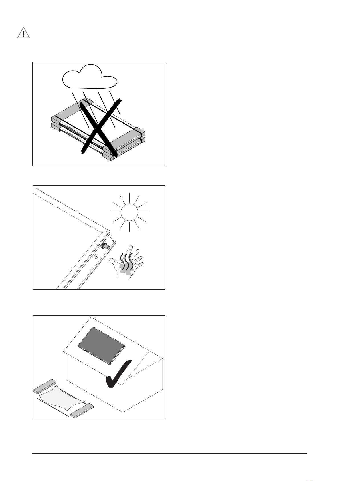
1.5 Notes on Proper Collector Storage
1.5.1 Proper Outdoor Storage of Collectors
●Remove protective film and lay down collectors with
glass pane up. Avoid direct ground contact (e.g. un-
derlay square timber). Avoid scratches on glass panes
by using spacers between collectors (e.g. wooden bat-
tens).
●When leaning collectors against walls or similar, use a
minimum inclination of 15° and apply spacers. Do not
use cardboard as under liner. If incorrectly stored, hu-
midity can enter the collectors through the air vents.
●Storing collectors in foil package may damage the
glass surface (see figure 2).
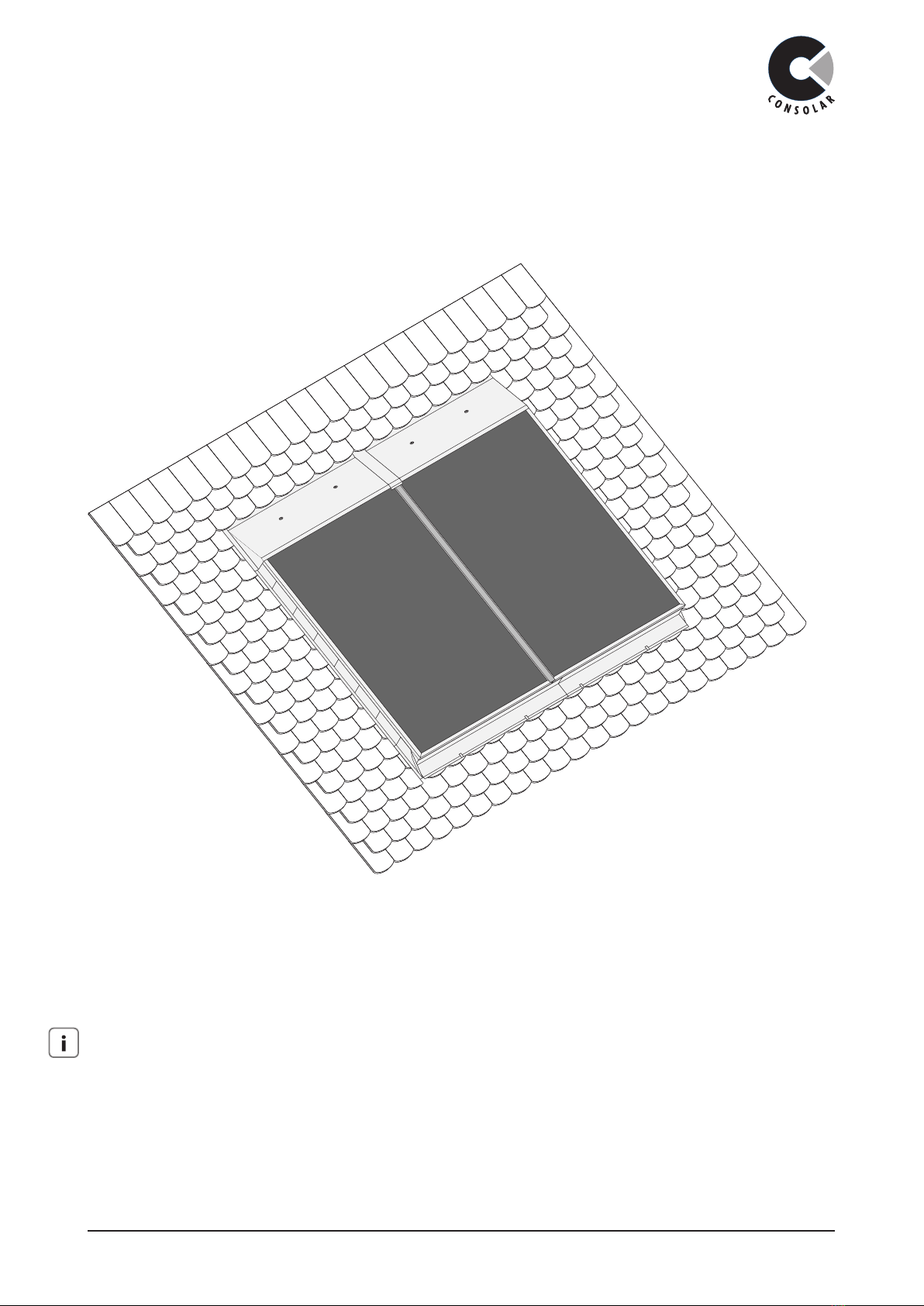
1.6 Pre-Installation Notes
Ensure technically correct roof structure
For roof integrated installation the space behind the col-
lector field has to be protected against uprising and ac-
cumulating humidity. Ensure that the roof is sufficiently
ventilated in the area of the in-roof collector field (see
“Installation Field” on page 6)
●Danger of open injuries when working with sharp
edged metal sheets and components!
●Risk of burns at collector connections as soon as uncov-
ered collector is exposed to the sun.
●Remove glass protection PE-LD film before commenc-
ing installation work!
●Do not subject the coollector connections to mechani-
cal loads or use as transportation handles. Specially de-
signed collector handles are available for this purpose.
●Keep a minimum distance between collectors and roof
structures such as chimneys, air vents, sky lights that
may release moist air. Otherwise there is a n increased
risk of excess humidity entering through the air vents
of the collector encasing.
Overheat Protection
For roof heating centrals and when 4 or more EURO col-
lectors with anti reflective glass are installed vertically, the
“Technical Information Solar Thermal Systems – Setup,
Commissioning and Maintenance” must be followed to
avoid damage to the solar circuit.
Ensure technically correct roof structure
For roof integrated installation the space behind the col-
lector field has to be protected against uprising and ac-
cumulating humidity. Ensure that the roof is sufficiently
ventilated in the area of the in-roof collector field (see
“Installation Field” on page 6)