atersa A-70M User manual

ER-0979/1997
UNE-EN ISO 14001
Gestión
Ambiental
AENOR
VERTEILER
Intl. Telefon
Tel. +34 961 038 430
Fax.+34 961 038 432
E-Mail: atersa@elecnor.com
ATERSA MADRID
C/ Embajadores, 187 - 3º
el: 915 178 452
Fax: 914 747 467
28045 Madrid - Spanien
T
ATERSA VALENCIA
P.Industria Juan Carlos I
46440 Almussafes
Valencia - Spanien
Tel: 902 545 111
Fax: 902 503 355
Avda. de la Foia, 14
ATERSA ITALIEN
Centro Direzionale Colleoni
Palazzo Liocorno - ingresso 1
20864 Agrate Brianza
(MB) - Italien
T
ax: +39 039 9160546
el: +39 039 2262482
F
DE-MU-41 (2)-A
MODUL
Installations-und Bedienungsanleitung
(www.atersa.com)
Letze überarbeitung: 23/01/12
Gedruckt auf Recyclingpapier
ASSOCIATION
Professionelle Photovoltaik-Modul
D

6
MODUL
Installations-und Bedienungsanleitung
DE-MU-41 (2)-A
2
1.- WARNHINWEISE
2.- STANDORTWAHL UND AUFSTELLWINKEL
3.- MONTAGE
Die Nichtbefolgung dieser Anleitung kann zur Zerstörung des Geräts oder zu Personenschäden führen.
Die Module können auf Grundstücken, Terrassen, Dächern und in Innenhöfen aber ebenso an Fassaden, Fenstern, Wänden, Simsen und auf Balkonen
installiert werden. ATERSA denn es hat eine Reihe von Zubehör.
Zur einwandfreien Funktionsweise der Module ist es wichtig, dass keine Hindernisse bestehen, die, zumindest während der Hauptstunden des Tages, die
Verschattungsfreiheit beeinträchtigen (Pflanzenwuchs, Schnee, andere Gebäude, Bauelemente, andere Module etc.).
In der nördlichem Hemisphäre sind die Panels sind Richtung Süden auszurichten. Im Folgenden finden Sie Annäherung für den Erhalt der maximalen
Jahresleistung. Es wird eine Konzeptionsphase von einem Jahr festgelegt, um die Dimensionierung des Generators auf das Verbrauchsbedürfnis und die
Sonneneinstrahlung abzustimmen. Der Neigungswinkel wird mithilfe der folgenden Tabelle bestimmt:
Das Modul darf nicht an einen Ort installiert werden, an dem es im Wasser steht oder kontinuierlich Wasser ausgesetzt ist, beispielsweise durch einen
Sprenger.
Die Montage in salzhaltiger Umgebung muss mit Isolatoren erfolgen, um eine galvanische Korrosion zwischem dem Modul und seiner Unterkonstruktion zu
verhindern.
Die in Reihe geschalteten Solarmodule müssen in derselben Ausrichtung und im selben Winkel angebracht werden. Außerdem sind sie in einem
Mindestabstand von 30cm von der Oberfläche anzubringen, damit die Belüftung gewährleistet ist.
Das Design der ATERSA-Module erlaubt den Wasserabfluss (das Rahmenrohr ist an den Enden offen).
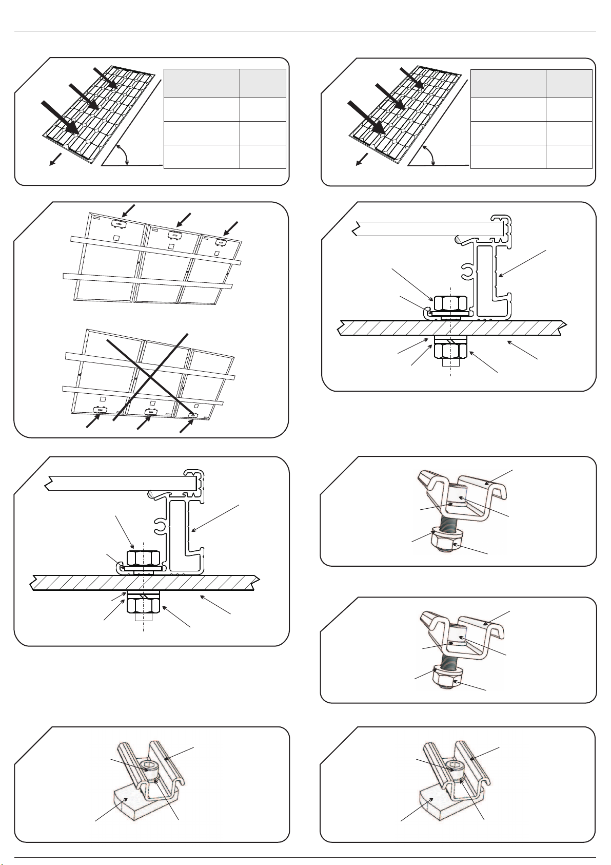
Die Module müssen auf festen und autonomen Konstruktionen angebracht werden, die keine Kräfte auf die Panels übertragen dürfen.
Die langen Seiten des Aluminiumrahmens des Moduls enthalten eine Reihe von Bohrungen von 6,7mm Duchmesser. Zur Montage über der Konstruktion ist
es empfehlenswert, M6-Schrauben aus rostfreiem Stahl zu verwenden. Das Anzugsdrehmoment für das Festziehen der Schrauben liegt zwischen 6 und
8Nm. Folgende Schrauben sind geeignet:
Die Schrauben sind immer mit dem Abstand B angebracht (mit Ausnahme für Module mit dem Format ½ 6” 4x9, bei denen der Abstand C ist), so wie auf
Bild 12 zu sehen. Es müssen mindestens 4 Fixierungen pro Modul angebracht werden.
Die Aluminiumrahmen des Photovoltaik-Moduls von ATERSA verfügen über seitliche Rinnen, die die Anbringung des Moduls auf dem Profil der Anlage
erleichtern. Für die Montage der Module wird ein Hook-System verwendet. Dieses System kann bei Standardkonstruktionen oder bei Führungsprofilen des
Typs “U” eingesetzt werden.
Die Montage auf Standardkonstruktionen wird mittels Klammer, Allen-Schraube M6x16, Federunterlegscheibe, flacher Unterlegscheibe und Mutter M6
durchgeführt.
Für diese Art von Montage ist ein perforiertes Profil des Typs “U” von 41x41 oder 41x21mm notwendig. Diese Elemente werden nicht mit dem Hook-System
mitgeliefert. Das nachfolgende Bild zeigt die vollständig montierte Einheit:
In korrosiver Umgebung (Salznebel) müssen Nylon-Unterlegscheiben verwendet werden.
Setzen Sie die ersten zwei Montagesätze auf und richten Sie sie vertikal auf einer Linie aus. Schrauben Sie die Allen-Schraube bis zum Ansatz ein.
Setzen Sie zwei weitere, vertikal auf einer Linie ausgerichteten Montagesätze auf und schieben Sie sie über die Schiene bis zum Anschlag mit dem
Panel.
Stellen Sie sicher, dass die Module vertikal und horizontal eben zueinander ausgerichtet sind und ziehen Sie die Schrauben bis zum Anschlag an, sodass sie
fest in der Führungsschiene verankert sind.
Die letzten beiden Montagesätze werden auf dieselbe Art und Weise angebracht, wie die ersten, aber in umgekehrter Reihenfolge. Wir fangen nun bei
einem bereits angebrachten Modul an und setzen die Montagesätze auf.
Das Anzugsdrehmoment für das Festziehen der Schrauben liegt zwischen 8 und 10 Nm.
Die Positionierung der Fixierungsklammern, ob des Typs "Hook" oder eines anderen Typs, erfolgt immer im Abstand B, wie im Bild 12 dargestellt (mit
Ausnahme von Modulen des Formats ½ 6” 4x9, bei denen der Abstand C ist). Es sind mindestens 4 Klammern pro Modul anzubringen.
Der Kabeldurchmesser ist wichtig, um zu verhindern, dass es zu Spannungsabfällen kommt, die zu Verlustleistungen in der Anlage führen. Als
Bezugsgröße sind nicht mehr als 1,5% Spannungsabfall zulässig.
Vergewissern Sie sich, dass die Anleitung für die in diesem Dokument aufgeführten Installationen befolgt wird. Reklamationen oder Garantieansprüche können nicht geltend gemacht
werden, wenn nicht wie beschrieben vorgegangen wurde.
Die in dieser Anleitung enthaltenen Sicherheitshinweise müssen für die Sicherheit des Nutzers genau befolgt werden.
Die Kabelführung muss als mechanischer Träger für die Kabelleiter fungieren und über die entsprechende Abdeckung gemäß der Verordnung über elektronische Anlagen mit
Niederspannung verfügen.
Die Bedienung hat durch qualifiziertes Personal zu erfolgen. Die Module erzeugen Strom, wenn sie der Sonne ausgesetzt werden. Die Reihenschaltung von mehreren Modulen kann
gefährliche Spannungen erzeugen. Um das elektrische Risiko während der Montage zu verringern, sollten die Module mit einem lichtundurchlässigen Material bedeckt werden.
Berühren Sie die Enden nicht mit beiden Händen und verwenden Sie immer Isolierwerkzeuge an den elektrischen Verbindungen.
Der Anschluss mit falscher Polarität zerstört die Bypass-Diode des Anschlusskastens.
Das Modul darf nicht konzentriertem Sonnenlicht ausgesetzt werden.
Unter normalen Bedingungen kann das Modul mehr Strom oder Spannung erzeugen, als für durchschnittliche Standardbedingungen angegeben. Dies ist bei der Wahl der Kapazität
des Zubehörs (Kabel, Sicherungen...) zu beachten. Die Voc- und Isc-Werte sind mit dem Faktor 1,25 zu muiltiplizieren.
Die Module dürfen NICHT im mittleren Teil der langen Aluminiumrahmen manipuliert werden.
WICHTIG: NICHTDie Module dürfen mit dem Anschlusskasten unten montiert werden, der Anschlusskasten muss oben liegen.
Montage auf Standardkonstruktionen:
Montage auf Führungsschiene Typ “U”:
*Hinweis:
Montage
KABELDURCHMESSER (Kupferdrahtstärke):
3.1.- Mechanische Installation
3.2.- Elektrische Installation
3.1.1.- Direkt über der Konstruktion
3 .1.2.- Befestigung mittels Hook-System
3.2.1.- Elektroanschluss Anschlusskasten
1B
2
3B
4B
5B
12
12

8B
7
3
Um den minimalen Kabeldurchmesser zu berechnen, kann die folgende Formel verwendet werden:
entspricht der Länge der Leitung in Metern ist die maximale Stromstärke in Ampere der maximal zulässige Spannungsabfall in Volt ist die
Leitfähigkeit desKupferdrahtesin Abhängigkeit von der Temperatur. Z.B.: Der Wert der Leitfähigkeit bei 90°C liegt bei
In der Tabelle zur maximalen Stromstärke des Kabelherstellers und der anwendbaren Norm nachschlagen.
Der Durchmesser des Kabels ist abhängig von der Kabelverschraubung. Im vorliegenden Fall liegt er zwischen 4,5 und 10mm. Das bereits gecrimpte
Kabelterminal zusammen mit dem Kabel einsetzen. Dieses darf in keinem Fall den maximal zulässigen Durchmesser überschreiten.
Die Kabel durch die Kabelverschraubungen führen und mit den Anschlussschrauben des Kastens sicher befestigen. Dabei die Polarität beachten, die für den
Stromkreis angegeben wird.
Es ist empfehlenswert, die Verkabelung mit Ring- oder Gabel-Kabelschuhen Maß M5 zu crimpen, da der Modulanschluss so zum einen leichter und zum
anderen sicherer erfolgt. Das Kabelterminal wird mit einer Mutter M5, einer flachen Unterlegscheibe und einer Zahnunterlegscheibe an den
Anschlussschrauben fixiert. Das Anzugsdrehmoment für das Festziehen der Schrauben liegt zwischen 3,8 und 4Nm. Die genannten Teile werden mit dem
Anschlusskasten mitgeliefert, mit Ausnahme des Kabels und des Kabelterminals (nach Modellen).
Das Kabel muss den Anforderungen für den Einsatz mit Photovoltaikanlagen entsprechen. Das Kabel, das ATERSA in seinen Modulen verwendet, ist ein UV-
beständiges, doppelt isoliertes Kabel für die Außeninstallation, 1kV und mit einer Arbeitstemperatur zwischen -40°C und 110°C.
Damit der Anschlusskasten weiterhin mit der Sicherheitsklasse II zertifiziert bleibt, müssen die Kabel ebenfalls der Klasse II entsprechen.
Die Reihenschaltung einer Anzahl von Panels darf die Vmax des Systems nicht überschreiten (siehe elektrische Daten des Panels).
Die Module und die Unterkonstruktion werden am selben Punkt geerdet. Damit wird sichergestellt, dass jede Art von Stromfluss in Richtung eines der
Komponenten der Anlage in keinem Fall den Monteur oder den Benutzer erreicht.
Der Rahmen ist aus Aluminium gefertigt. Die Erdungskabel müssen am Erdungsanschluss des Rahmens angeschlossen werden (siehe Figur 9). Dafür ist
ein 4mm -Kabel zu verwenden.
Für den Erdungsanschluss der Module ist eine Gewindeschraube mit flachem Kopf aus rostfreiem Stahl von 4,2mm Durchmesser und einer Länge zwischen
4,5 und 16mm zu verwenden. Dies wird mit einer halb isolierten Kabelschuhöse von 4mm verbunden.
Vergewissern Sie sich, dass das Kabelterminal richtig zwischen dem Kabel und dem Rahmen des Moduls sitzt. Das Kabelterminal muss richtig an das Kabel
gecrimpt werden und perfekt mit dem Aluminiumrahmen in Kontakt stehen.
Am Solarmodul sind zwei Vorbohrungen zu diesem Zweck angebracht, die mit dem Erdungssymbol gekennzeichnet sind (siehe Figur 12). Ihr Durchmesser
beträgt 4mm. Das Anzugsdrehmoment für das Festziehen der Schraube liegt zwischen 1,5 und 2Nm.
Das Photovoltaik-System wird gemäß den lokalen und nationalen Richtlinien geerdet.
Alle für die Anlage verwendeten Kabel müssen fixiert werden, um Bewegung zu verhindern, die zu Schäden oder Brüchen führen kann.
ATERSA verfügt über einen Kabelflansch für die Anbringung und die Führung der Kabel.
Die Verwendung des "Brida Hook"-Flansches vereinfacht die Führung und Fixierung der Anschlusskabel entlang des Aluminiumrahmens.
Der Flansch kann sowohl für das Hook V1 als auch das Hook V4-Profil genutzt werden. Die korrekte Platzierung für die Profile wird in der folgenden Grafik
dargestellt:
Die Solarmodule von ATERSA benötigen so gut wie keinerlei Wartung. Es ist ausreichend, regelmäßig sicherzustellen, dass sich auf dem Glas des Panels
keine Schmutzablagerungen bilden. Wenn eine Reinigung notwendig ist, führen Sie diese mit einem Schwamm und Seifenwasser durch. Verwenden Sie
dazu niemals scheuernde Materialien, die das Glas beschädigen können. NICHT mit Druckwasser reinigen. Vermeiden Sie eine Reinigung, wenn die Module
stark aufgeheizt sind (mittags).
Überprüfen Sie die Kabel und Elektroanschlüsse. Überprüfen Sie, dass die mechanischen Komponenten schadfrei sind.
Die Wartung hat durch dafür qualifiziertes Personal zu erfolgen, da hierbei ggf. mit gefährlichen Spannungen gearbeitet wird.
Die Solarmodule sind aus quadratischen Hochleistungszellen gefertigt und in der Lage, auch bei niedriger Sonneneinstrahlung Strom zu erzeugen. Alle
Modelle von 70W bis 310W sind mit Bypass-Dioden in den Anschlusskästen ausgestattet.
Die technischen Merkmale der Module entnehmen Sie den folgenden Tabellen und Grafiken.
ATERSA übernimmt die Garantie für die Ausgangsleistung über 25 Jahre und für Produktionsfehler über 10 Jahre.
Gemäßder IEC-Norm 61730-1 ist dieses Produkt (Modul ATERSA) der Klasse A zuzuordnen und gehört zu den Modulen, die mit Spannungen über 50V oder
einer Leistung von über 240W arbeiten, bei denen der Zugang zu einem Generalschalter vorgesehen ist. Die Module werden innerhalb ihrer Kategorie in
Sicherheitsklassen eingeteilt. Die Module erfüllen die Anforderungen der Klasse II.
Alle ATERSA-Module entsprechen den Normen IEC 61215:2005 und IEC 61730. Sie werden hergestellt gemäß den Qualitätsnormen UNE-EN ISO
9001:2008 und UNE-EN ISO 14001:2004.
Die Formate 6” 6x10 und 6” 6x12 sind ebenfalls nach UL 1703 zertifiziert.
Detaillierte Informationen zu den Garantieleistungsregelungen erhalten Sie auf unserer Webseite
Atersa behält sich das Recht vor, die Produktspezifizierungen ohne vorherige Ankündigung zu modifizieren.
GESAMTDURCHMESSER Außendurchmesser
3.2.2.- Erdung
Anbringung und Führung des Elektro-Kabels
2
2
4. - W A R T U N G
5.- TECHNISCHE DATEN
6.- GARANTIEN UND ZERTIFIZIERUNGEN
L , I , und
= 44
(*)
:
:
Alle Bilder, die durch Zahlen in diesem Handbuch verwiesen wird, sind im Anhang zu finden.
MAX
90
( ):
ELEKTROANSCHLUSS:
www.atersa.com
*Hinweis
3.3.-
mmSection (IL MAX
×
××
³2
)
2
V
gT
gT
V
g
9
10
11
X
DE-MU-41 (2)-A
MODUL
Installations-und Bedienungsanleitung

* Wahlweise und auf Bestellung ist ATERSA ausgestatten mit Anschlusskasten des Typs IP65.
** Solarkabel 4mm2
*** Überstromschutz (Max. empfohlen).
**** Ohne zusätzliche Schutzeinrichtungen.
(0/+5 W)
15,66%
8,34 A
8,89 A
37,76 V
30,57 V
(0/+5 W)
1645x990x40
1639x984x32
3 / SCHOTTKY
Ja (1100mm, Schwarz)
15,97%
8,44 A
8,99 A
37,90 V
30,79 V
(0/+5 W) (0/+5 W)
36 ½
778x659x35
616
68
389
6,20
No
192
Hook V1
QUAD I 54P
2 / SCHOTTKY
Nein
15
43
2
15,1 A
18A / 45V / 175ºCm
14,63%
4,13 A
4,39 A
22,57 V
18,21 V
± 8%
15,60%
4,28 A
4,55 A
22,84 V
18,63 V
± 8%
14,39%
7,88 A
8,45 A
22,30 V
17,79 V
± 5%
15,42%
8,25 A
8,79 A
22,57 V
18,21 V
± 5%
16,45%
8,56 A
9,11 A
22,84 V
18,63 V
± 5%
36
1476x659x35
616
200
738
11,90
No
416
Hook V1
QUAD I 54P
2 / SCHOTTKY
Nein
41
15
2
15,1 A
18A / 45V / 175ºCm
60
15,04%
8,14 A
8,69 A
37,48 V
30,13 V
(0/+5 W)
15,35%
8,24 A
8,79 A
37,62 V
30,35 V
938
284,5
822,5
21,50
500,5
Hook V4
24
1000 V
-0,43%/ºC
-0,34%/ºC
0,03%/ºC
1000 V
-0,43%/ºC
-0,34%/ºC
0,03%/ºC
13,65%
3,94 A
4,22 A
22,30 V
17,79 V
Eletrische Daten gemessen in STC. TONC: 47±2ºC
Größe Panel (mm ± 2mm)
PHYSISCHE EIGENSCHAFTEN
Isc-Temperatur-Koeffizient ( )
á
Voc-Temperatur-Koeffizient ( )â
Leerlaufspannung ( )Voc
Kurzschlussstrom ( )Isc
Spannung Bei Maximale Leistung (Vmp)
Anzahl der in Reihe geschalteten Zellen
Maximale Systemspannung
P-Temperatur-Koeffizient ( )
ã
Schutzdioden ( )Amperie/Vmax/Tj
Schutzdioden (Anzahl/Typ)
Sicherung in Serie (A) (***)
Max. Anzahl von Panels in Reihenschaltung
Max. Anzahl von Panels in Paralellschaltung (****)
Max. Inversstrom (während 2h)
Strom Bei Maximale Leistung ( )Imp
Größe Lam. (mm ± 2mm; Fig. 13)
A-75M A-80M
½ 6” 4x9
A-140M
6” 4x9 6” 6x10
A-70M
ELEKTRISCHE CHARAKTERISTIKA
± 8%
255 W 260 W75 W 80 W 140 W 150 W 160 W 245 W 250 W70 W
A-150M A-160M
1000 V
-0,43%/ºC
-0,34%/ºC
0,03%/ºC
QUAD I 54P
15
2
15,1 A
18A / 45V / 175ºCm
A-245M A-250M A-255M A-260M A-290M
290 W
14,90%
8,04 A
8,60 A
44,11 V
36,11 V
A-295M
295 W
(0/+5 W)
15,16%
8,13 A
8,68 A
44,37 V
36,31 V
A-300M
300 W
(0/+5 W)
15,42%
8,22 A
8,76 A
44,63 V
36,51 V
6” 6x12
72
1000 V
-0,43%/ºC
-0,34%/ºC
0,03%/ºC
1965x990x40
938
445,5
982,5
24
No
660,5
Hook V4
QUAD I 54P
Ja (1250mm, Schwarz)
3 / SCHOTTKY
18A / 45V / 175ºCm
15,1 A
15
21
2
Toleranz
A (mm) (Figur 12)
B (mm) (Figur 12)
C (mm) (Figur 12)
D (mm) (Figur 12)
Gewicht (kg etwa)
Profiltyp
Anschlusskasten (*)
Kabel (**)
Format
Leistung
A-305M
305 W
(0/+5 W)
15,68%
8,31 A
8,84 A
44,89 V
36,71 V
15,94%
8,40 A
8,92 A
45,15 V
36,91 V
(0/+5 W)
310 W
A-310M
Modulwirkungsgrad
4
DE-MU-41 (2)-A
MODUL
Installations-und Bedienungsanleitung

Professional Photovoltaic Module
ER-0979/1997
UNE-EN ISO 14001
Gestión
Ambiental
AENOR
DISTRIBUTOR
Intl. Phone numbers
Tel. +34 961 038 430
Fax.+34 961 038 432
E-Mail: atersa@elecnor.com
ATERSA MADRID
C/ Embajadores, 187 - 3º
el: 915 178 452
Fax: 914 747 467
28045 Madrid - Spain
T
ATERSA VALENCIA
P.Industria Juan Carlos I
46440 Almussafes
Valencia - Spain
Tel: 902 545 111
Fax: 902 503 355
Avda. de la Foia, 14
ATERSA ITALY
Centro Direzionale Colleoni
Palazzo Liocorno - ingresso 1
20864 Agrate Brianza
(MB) - Italy
T
ax: +39 039 9160546
el: +39 039 2262482
F
EN-MU-41 (2)-A
MODULE
Installation and User Manual
(www.atersa.com)
Latest revision: 23/01/12
Printed on recycled paper
ASSOCIATION
N

6
MODULE
Installation and User Manual
EN-MU-41 (2)-A
2
1.- WARNINGS
2.- POSITIONING AND INCLINATION
3.- INSTALLATION
Failure to follow these instructions could result in the destruction of the equipment or personal injury.
Do install the modules with the junction box in the lower side.
The aluminium frames of ATERSA’s photovoltaic modules have side channels that make it easier to fix the module onto the profiles of the installation.
The Hook Fixing System is used to install the modules.This system can be installed on standard structures or “U” type guide rail.
Fixing on standard structures is carried out using the dead-end clamp, the M6 x 16 Allen screw, Grower washer, flat washer and M6 nut.
For this type of installation you need a 41 x 41 mm or 41 x 21 mm "U" type perforated profile. These elements do not come with the Hook Fixing System.
The assembled fixing should look like the picture shown in next figure:
*Note: In corrosive environments (salt spray), place nylon washers to insulate the panel from the metal parts of the structure.
Put the first two fixing sets in place, and ensure they are vertically aligned. Fully tighten the Allen screw.
Attach the other two fixing sets, aligning them vertically and move them along the rail until they reach the panel.
Check that the modules are horizontally and vertically aligned and fully tighten the screws to ensure the modules are firmly fixed to the guide rail.
The final fixing sets should be attached in the same way as the first two but in reverse. Take a module that is already in place and then attach the set of
fixings.
Ensure that the installation instructions provided in this document are followed. Guarantees or claims will not be valid if the described process has not been followed.
The safety instructions contained in this manual must be strictly followed in order to guarantee the safety of the user.
The cable pathway must provide mechanical support for the conductors and must provide sufficient protection, in accordance with the Low Voltage Electrotechnical Regulations
(REBT).
It must be handled by qualified personnel only. When exposed to the light, the modules generate electricity. If several modules are connected in series, dangerously high voltages may
be generated. To reduce potential electrical hazards during the installation process, it is adv
IMPORTANT: NOT
Installation on standard structures:
Installation on “U” type guide rail:
isable to cover the modules with an opaque material. Do not touch the terminals with both
hands and always use insulated tools on the electrical connections.
Reversing the polarity of the cables destroys the bypass diodes of the junction box.
The module is not suitable for use under concentrated sunlight.
In normal conditions, the module can produce more current or voltage than the indicated for standard measurement conditions. So that, when dimensioning the system (cables
section, fuses,…) the Isc and Voc values should be multiplied by 1,25.
Modules must NOT be manipulated from the central part of the long sides of the frame.
The modules may be installed on plots of land, terraces, roofs and patios. ATERSA provides a series of accessories for installations on façades, windows,
balconies, walls and cornices.
In order to ensure optimum performance the modules must not be placed in the shadow of other objects (plants, snow, buildings, construction elements,
other modules, etc.), at least during the main hours of daylight.
The panels must face south if installed in the northern hemisphere.Guidelines for achieving maximum annual power output from a fixed installation are
provided below. A design period will be established in order to calculate the size of generator in accordance with the consumption requirements and
radiation. To determine the optimum inclination we will use the following table:
Do not install the solar module in a location where it could be immersed in water or continually exposed to water, e.g. from a sprinkler.
The installation in a saline environment must be done with isolators to prevent galvanic corrosion between the module and the support structure.
When solar modules are connected in series, they must all face the same direction and have the same angle of inclination. There must also be a proper gap
(minimum 30cm) between the module and the surface for ventilation purposes.
The ATERSA modules design allows the correct evacuation of water. They have open edges in the inside tube.
The modules must be installed on independent fixed structures. The structure must not transmit stress to the modules.
The longest side of the aluminium frame has a series of 6,7mm diameter drill holes. Use M6 stainless steel bolts to install it on the structure and the proper
torque values should be between 6 to 8Nm. The following bolt system should be employed:
The placement of the bolts, will be always at the distance B (except for ½ 6” 4x9 format modules, where the distance must be C), as shown in the image
number 12. Minimum 4 bolts per module must be situated.
The proper torque values should be between 8 to 10Nm.
The placement of the dead end clamp (Hook clamp or another type), will be always at the distance B (except for ½ 6” 4x9 format modules, where the
distance must be C), as shown in the image number 12. Minimum 4 dead end clamps per module must be situated.
Appropriate cable sections must be used to prevent voltage drops, which could cause a drop in the power of the installation. As a rule, voltage drops in
excess of 1,5% must not be allowed.
Installation
CABLE SECTION (Copper section):
3.1.- Mechanical Installation
3.2.- Electrical Installation
3.1.1.- Directly on the Structure
3 .1.2.- Hook Fixing System
3.2.1.- Electrical Connection of the Junction Box
1A
2
3A
4A
5A
12
12

8A
7
3
Use the following formula to calculate the section:
Where L is the lenght of the line in meters, I is the maximum current in amps, the maximum permited voltage drop in volts is and is the copper
conductivity at temperature T. E.g The copper conductivity at 90ºC would be = 44.
(*)Check table of intensities max. of manufacturer's cable and the applicable regulations.
The section of the cable depends on the type of cable gland used. In this case, it must have a diameter of between 4.5 mm and 10 mm. Install the terminal
already crimped together with the cable, which must never exceed the maximum diameter admitted by the 10 mm cable gland.
Pass the cables through the cable glands and firmly fasten the cables to the connection screws in the box, paying particular attention to the polarity, which
is shown on the circuit.
It is recommended that the cables should be crimped with spade or ring terminals for M5, as this guarantees and facilitates the connection of the module.
The cable terminal must be fastened to the connection screw using a M5 nut, a flat washer and a serrated washer and the proper torque values should be
between 3,8 to 4Nm. The junction box is always supplied with these components, with the exception of the cable and terminal (according to models).
For the junction box to maintain its Class II safety standard, the cables must also be Class II.
Connect the modules and the support structure to ground, which will ensure that any current leakage to any of the components of the installation will not
reach the installer or user under any circumstances.
The module frame material is aluminium. Ground wires must be connected to the module’s frame at the ground location (Figure 9). The ground wire must
be
To ground the modules, you must use a stainless steel lug terminal and a self-tapping screw between 4,2x4,5mm and 4,2x16mm. Terminal lug and
self-tapping screw must be stainless steel.
Make sure the lug terminal is placed between the wire and module frame. The wire must fully clamped with the lug terminal and must make good contact
with the frame.
There are two drill holes in the solar modules for this purpose, which are marked with a ground connection (Earthing hole 4mm) (Figure 12). The proper
torque values should be between 1,5 to 2Nm.
The photovoltaic system will be earthed according to the local and national regulations.
All the cables used in the installation must be secured in order to prevent movements that could cause damage or breakages.
ATERSA supplies a Clamp for the installation and guiding of these cables.
The Hook Clamp greatly assists the task of guiding and securing the connection cables along the length of the aluminium frame.
The Hook Clamp can be used on both the Hook V1 and Hook V4 profiles.
ATERSA solar modules hardly require any maintenance. It is sufficient to regularly check that dirt has not accumulated on the glass of the panel. Should this
be the case, clean the glass with a sponge and soapy water. Never use abrasive products that could damage the glass. Do NOT use water jet cleaning
systems. Do not clean the panels at their hottest (midday).
Check the cables and electrical connections. Check that the mechanical components are not damaged.
Maintenance work should be carried out by qualified personnel, as it could involve working with dangerously high voltages.
Our solar modules are made from high-efficiency square cells that are capable of producing power with low solar radiation. All the models from 70W to
310W have by-pass diodes in the junction box.
The technical characteristics of the modules are shown in the attached table and grapichs.
ATERSA guarantees the power output for up to 25 years and provides a 10-year warranty covering manufacturing flaws.
The modules comply with IEC 61215:2005 and IEC 61730 standards, in addition to being manufactured under strict UNE-EN ISO 9001:2008 and UNE-EN
ISO 14001:2004 quality standards.
The modules 6” 6x10 and 6” 6x12 are also certified by UL 1703.
For more extensive information about the terms of the warranty, please see our website:
ATERSA reserves the right to modify the product specifications without notice.
All images that are referenced by numbers in this manual are found in the Annex.
MAX
90
TOTAL SECTION (External diameter):
ELECTRICAL CONNECTION:
www.atersa.com
*Note:
The cable must fulfill the requirements to be used in photovoltaic systems. The cable used by ATERSA in its modules is for outdoors use, UV resistent,
double isolation layer, 1kV, working temperature range -40ºC to 110ºC.
It is not recomended to connect modules in series with a total Voc higher than the system Vmax shown at the module label.
4mm .
4mm
The correct placing of it is the one shown in figure:
According to the norm IEC 61730-1, the application class for this product (ATERSA module) is class A, which corresponds to modules working in voltages
above 50V or powers above 240W where the access to a general contact is forecasted. The modules clasified for security within this category fulfill the
requirements for ClassII.
3.2.2.- Ground connection
2
2
4. - M A I N T E N A N C E
5.- TECHNICAL SPECIFICATIONS
6.- GUARANTEE AND CERTIFICATES
3.3.- Installation and guiding of the electrical cables
mmSection (IL MAX
×
××
³2
)
2
V
gT
gT
V
g
9
10
11
MODULE
Installation and User Manual
EN-MU-41 (2)-A
X

* As an option ATERSA has connection boxes with the IP65 version on request.
** Solar Cable 4mm2
*** Overcurrent protection (Max. recommended).
**** Without any additional protection.
(0/+5 W)
15,66%
8,34 A
8,89 A
37,76 V
30,57 V
(0/+5 W)
1645x990x40
1639x984x32
3 / SCHOTTKY
Yes (1100mm, Black)
15,97%
8,44 A
8,99 A
37,90 V
30,79 V
(0/+5 W) (0/+5 W)
36 ½
778x659x35
616
68
389
6,20
No
192
Hook V1
QUAD I 54P
2 / SCHOTTKY
No
15
43
2
15,1 A
18A / 45V / 175ºCm
14,63%
4,13 A
4,39 A
22,57 V
18,21 V
± 8%
15,60%
4,28 A
4,55 A
22,84 V
18,63 V
± 8%
14,39%
7,88 A
8,45 A
22,30 V
17,79 V
± 5%
15,42%
8,25 A
8,79 A
22,57 V
18,21 V
± 5%
16,45%
8,56 A
9,11 A
22,84 V
18,63 V
± 5%
36
1476x659x35
616
200
738
11,90
No
416
Hook V1
QUAD I 54P
2 / SCHOTTKY
No
41
15
2
15,1 A
18A / 45V / 175ºCm
60
15,04%
8,14 A
8,69 A
37,48 V
30,13 V
(0/+5 W)
15,35%
8,24 A
8,79 A
37,62 V
30,35 V
938
284,5
822,5
21,50
500,5
Hook V4
24
1000 V
-0,43%/ºC
-0,34%/ºC
0,03%/ºC
1000 V
-0,43%/ºC
-0,34%/ºC
0,03%/ºC
13,65%
3,94 A
4,22 A
22,30 V
17,79 V
Electrical specifications measured in STC. TONC: 47±2ºC
Dimensions (mm ± 2mm)
PHYSICAL CHARACTERISTICS
Isc ( ) Temperature Coefficient
á
Voc ( ) Temperature Coefficientâ
Open Circuit Voltage ( )Voc
Short-circuit Current ( )Isc
Max. Power Voltage ( )Vmp
Number of cells in series
Máxima Tensión del Sistema
P ( ) Temperature Coefficient
ã
Protection Diodes ( )Amperes/Vmax/Tj
Protection Diodes (Nº/Type)
Serial Fuse (A) (***)
Max. Nº Modules in Serie
Max. Nº Modules in Parallel (****)
Max. Reverse Current (during 2h)
Max. Power Current ( )Imp
Laminate Dim. (mm ± 2mm; Fig. 13)
A-75M A-80M
½ 6” 4x9
A-140M
6” 4x9 6” 6x10
A-70M
ELECTRICAL CHARACTERISTICS
± 8%
255 W 260 W75 W 80 W 140 W 150 W 160 W 245 W 250 W70 W
A-150M A-160M
1000 V
-0,43%/ºC
-0,34%/ºC
0,03%/ºC
QUAD I 54P
15
2
15,1 A
18A / 45V / 175ºCm
A-245M A-250M A-255M A-260M A-290M
290 W
14,90%
8,04 A
8,60 A
44,11 V
36,11 V
A-295M
295 W
(0/+5 W)
15,16%
8,13 A
8,68 A
44,37 V
36,31 V
A-300M
300 W
(0/+5 W)
15,42%
8,22 A
8,76 A
44,63 V
36,51 V
6” 6x12
72
1000 V
-0,43%/ºC
-0,34%/ºC
0,03%/ºC
1965x990x40
938
445,5
982,5
24
No
660,5
Hook V4
QUAD I 54P
Yes (1250mm, Black)
3 / SCHOTTKY
18A / 45V / 175ºCm
15,1 A
15
21
2
Tolerance
A (mm) (Figure 12)
B (mm) (Figure 12)
C (mm) (Figure 12)
D (mm) (Figure 12)
Weight (kg approx)
Frame type
Connection Box (*)
Cables (**)
Format
Power
A-305M
305 W
(0/+5 W)
15,68%
8,31 A
8,84 A
44,89 V
36,71 V
15,94%
8,40 A
8,92 A
45,15 V
36,91 V
(0/+5 W)
310 W
A-310M
Module Efficiency
4
EN-MU-41 (2)-A
MODULE
Installation and User Manual

Módulo Fotovoltaico Profesional
ES
ER-0979/1997
UNE-EN ISO 14001
Gestión
Ambiental
AENOR
MU-41 (2)-A
ANEXO
ASSOCIATION
ES
FR
N
Professional Photovoltaic Module
Module Protovoltaïque Professionnel
Professionelle Photovoltaik-Modul
Modulo Fotovoltaico Professionale
Professionele Fotovoltaïsche Module
IT
NL
D

ANEXO
MU-41 (2)-A
2
HORIZONTAL
INCLINACIÓN
INCLINATION
INCLINAISON
LUZ SOLAR
SOLAR LIGHT
LUMIÈRE SOLAIRE
SUR/SOUTH/SUD
(Hemisferio norte/North hemisphere/Hémisphère nord )
INCLINACIÓN
INCLINATION
INCLINAISON
INVIERNO
WINTER
HIVER
PERIODO DE DISEÑO
DESIGN PERIOD
PÉRIODO DE DIMENSIONNEMENT
VERANO
SUMMER
ÉTÉ
ANUAL
ANNUAL
ANNUEL
Latitud +10º
Latitude +10º
Latitude +10º
Latitud -20º
Latitude -20º
Latitude -20º
Latitud -10º
Latitude -10º
Latitude -10º
1A
HORIZONTAL
NEIGUNG
INCLINAZIONE
HELLINGSHOEK
SÜD/SUD/ZUID
(Nördliche Hemisphäre/Emisferio settentrionale/Noordelijk halfrond )
WINTER
INVERNO
WINTER
SOMMER
ESTATE
ZOMER
JÄHRLICH
ANNUALE
JAARLIJKS
Breitengrad +10º
Latitudine +10º
Breedtegraad +10º
Breitengrad -20º
Latitudine -20º
Breedtegraad -20º
Breitengrad -10º
Latitudine -10º
Breedtegraad -10º
SONNENLICHT
LUCE SOLARE
ZONLICHT
NEIGUNG
INCLINAZIONE
HELLINGSHOEK
KONZEPTIONSPHASE
PERIODO DI PROGETTAZIONE
PERIODE VAN METING
1B
RECOMENDADO/RECOMMENDED/RECOMMANDÉ
EMPFOHLEN/RACCOMANDATO/AANBEVOLEN
2
NO
* Nota: Utilizar Arandela M6 DIN 9021 para perfil Hook V4.
Utilizar Arandela M6 DIN 125 para perfil Hook V1.
* Note:
* Remarque:
Use M6 DIN 9021 washer for Hook V4 profile.
Use M6 DIN 125 washer for Hook V1 profile.
Utiliser des rondelles M6 DIN 9021 pour les profilés Hook V4.
Utiliser des rondelles M6 DIN 125 pour les profilés Hook V1.
ARANDELA PLANA M6
M6 WASHER
RONDELLE M6
ARANDELA DE PRESIÓN M6
M6 GROWER WASHER
RONDELLE GROWER M6
TORNILLO M6
M6 BOLT
BOULON M6
3A
MARCO
FRAME
CADRE
TUERCA M6
M6 NUT
ÉCROU M6
ESTRUCTURA
STRUCTURE
STRUCTURE
*
*
*
ARANDELA PLANA M6
M6 WASHER
RONDELLE M6
ARANDELA DE PRESIÓN M6
M6 GROWER WASHER
RONDELLE GROWER M6
ARANDELA PLANA M6
M6 WASHER
RONDELLE M6
TUERCA M6
M6 NUT
ÉCROU M6
TORNILLO ALLEN M6x16
M6x16 ALLEN BOLT
BOULON ALLEN M6x16
GRAPA HOOK
DEAD-END CLAMP
PIÈCE FIXATION
4A
FLACHE UNTERLEGSCHEIBE M6
RONDELLA PIANA M6
VLAKKE SLUITRING M6
SCHRAUBE M6
BULLONE M6
BOUT M6
3B
RAHMEN
TELAIO
FRAME
MUTTER M6
DADO M6
MOER M6
KONSTRUKTION
STRUTTURA
DRAAGFRAME
*
*
*
FLACHE UNTERLEGSCHEIBE M6
RONDELLA PIANA M6
VLAKKE SLUITRING M6
FEDERUNTERLEGSCHEIBE M6
RONDELLA GROWER M6
BORGRING M6
* Hinweis: Verwenden Sie M6 DIN 9021 für das Profil Hook V4..
Verwenden Sie M6 DIN 125 für das Profil Hook V1.
* N.B.:
* Voetnoot:
Utilizzare la rondella M6 Din 9021 per il profilo Hook V4.
Utilizzare la rondella M6 DIN 125 per il profilo Hook V1.
Gebruik sluitring M6 DIN 9021 voor profiel Hook V4.
Gebruik sluitring M6 DIN 125 voor profiel Hook V1.
TORNILLO ALLEN M6x20
M6x20 ALLEN BOLT
BOULON ALLEN M6x20
GRAPA HOOK
DEAD-END CLAMP
PIÈCE FIXATION
ARANDELA DE PRESIÓN M6
M6 GROWER WASHER
RONDELLE GROWER M6
TUERCA GUIA M6
M6 GUIDE NUT
ÉCROU GUIDE M6
5A
ALLEN-SCHRAUBE M6x20
BULLONE ALLEN M6x20
INBUSBOUT M6x20
HOOK-KLAMMER
MORSA HOOK
HOOK-AFSPANKLEM
FEDERUNTERLEGSCHEIBE M6
RONDELLA GROWER M6
BORGRING M6
GUIDE MUTTER M6
DADO GUIDA M6
GIDS MOER M6
5B
FEDERUNTERLEGSCHEIBE M6
RONDELLA GROWER M6
BORGRING M6
FLACHE UNTERLEGSCHEIBE M6
RONDELLA PIANA M6
VLAKKE SLUITRING M6
MUTTER M6
DADO M6
MOER M6
ALLEN-SCHRAUBE M6x16
BULLONE ALLEN M6x16
INBUSBOUT M6x16
HOOK-KLAMMER
MORSA HOOK
HOOK-AFSPANKLEM
4B

Dmax>=Dterminal
7
17± 2 mm
6
3
TUERCA
NUT
ÉCROU
ARANDELA
WASHER
RONDELLE
ARANDELA DENTADA
JAGGED WASHER
RONDELLE DENTÉE
CIRCUITO
CIRCUIT
CIRCUIT
TERMINAL DE HORQUILLA O REDONDO
RING OR FORK TERMINAL
COSSE À FOURCHE OU RONDE
8A
9
HOOK V1
2
HOOK V1
1
1
2
HOOK V4
HOOK V4
10
HOOK V4
HOOK V1
11
HOOK V1
Para módulos < 180 Wp
For modules < 180 Wp
Pour modules < 180 Wp
Für module < 180 Wp
Per moduli da < 180 Wp
Voor modulen < 180 Wp
MUTTER
DADO
MOER
UNTERLEGSCHEIBE
RONDELLA
SLUITRING
ZAHNUNTERLEGSCHEIBE
RONDELLA DENTATA
TANDVEERRING
STROMKREIS
CIRCUITO
ELEKTRISCHE CIRCUIT
RING-ODER GABEL-KABELSCHUH
TERMINALE A FORCELLA O ROTONDO
SPADE OF RING KABELSCHOEN
8B
ANEXO
Para módulos > 180 Wp
For modules > 180 Wp
Pour modules > 180 Wp
Für module > 180 Wp
Per moduli da > 180 Wp
Voor modulen > 180 Wp
MU-41 (2)-A

A 80 mm.
B 11 mm.
Dimensiones en mm
Dimensions in mm
Dimensions en mm
Größe in mm
Dimensioni in mm
Afmetingen in mm
12
6,7
A
D
C
B
HOOK V1
29
35
HOOK V4
38
40
13
225±25.0 595±25.0 595±25.0 225±25.0
B
1639
5
15
*
A
984
32
4
* Las áreas marcadas en el dibujo (A y B) están destinadas a la fijación del laminado y
garantizar su correcta instalación.
Utilizar siempre sistemas de fijación que no dañen al laminado.
* The areas marked in the drawing (A and B) are intended for the fixation of the laminate and
ensure proper installation.
Always use fastening systems that do not damage the laminate.
* Les zones marquées dans le dessin (A et B) sont destinés à la fixation du stratifié et assurer
une bonne installation.
Toujours utiliser des systèmes de fixation qui n'endommagent pas le stratifié.
ANEXO
* Die Flächen in der Zeichnung (A und B) sind für die Fixierung des Laminats bestimmt und eine
ordnungsgemäße Installation.
Es sind grundsätzlich Befestigungssysteme zu gebrauchen, die die Laminierung nicht beschädigen.
* Le aree contrassegnate nel disegno (A e B) sono destinati per il fissaggio del laminato e garantire
una corretta installazione.
Utilizzare sempre sistemi di fissaggio che non danneggino il laminato.
* De gebieden gemarkeerd in de tekening (A en B) zijn bestemd voor de fixatie van het laminaat en
zorgen voor een correcte installatie.
Gebruik altijd een montagesysteem dat het laminaat niet kan beschadigen.
MU-41 (2)-A
This manual suits for next models
14
Table of contents
Languages:
Other atersa Solar Panel manuals
Popular Solar Panel manuals by other brands

Unitek
Unitek Unisun M 5.12M manual

TrickleStar
TrickleStar TS601P-2 100 W Setup guide

STIEBEL ELTRON
STIEBEL ELTRON Tegreon 265 P Operation and installation

Gasolarxy
Gasolarxy PG-GSP100W Installation guide & manual

CNPV
CNPV CNPV-PS-M-S0010-IEC Installation instruction

NDS
NDS DOMETIC BS 115WP Installation and operating manual

GRIDFREE
GRIDFREE TINY HOUSE installation manual

Clean Portable Power
Clean Portable Power CPP 200W FOLDING SOLAR PANEL instructions

PowerTech
PowerTech ZM9157 user manual

Battery Power Solutions
Battery Power Solutions BPS SP40 manual

GOSUN
GOSUN SOLAR 10 user manual

Chamberlain
Chamberlain SP10W12V installation guide