Bison Garfield GCA1250HC User manual

䴀伀䐀䔀䰀
䜀䌀䄀㈀㔀 䠀䌀
伀倀䔀刀䄀吀伀刀ᤠ匀 䴀䄀一唀䄀䰀
䌀愀爀爀礀ⴀ䄀氀氀 䔀樀攀挀琀椀漀渀 匀挀爀愀瀀攀爀
倀甀琀 䐀䤀刀吀 椀渀 椀琀猀 瀀氀愀挀攀⸀

1250 CARRY ALL
Operator's Manual
12.5 YD. CU., DOLLY

1
TABLE OF CONTENTS
INTRODUCTION 2
IMPORTANT SAFETY INFORMATION 3
BE AWARE OF SIGNAL WORDS 3
PREPARE FOR EMERGENCIES 4
SHUTDOWN AND STORAGE 4
ASSEMBLY AND SET-UP 4
PARTS MANUAL 4
1250 HYDRAULIC SYSTEM 9
DRAWBAR HOOK-UP 11
OPERATION 12
SETTING THE VALVES 12
BLADES 13
WARRANTY 14

2
INTRODUCTION
Welcome! You are now the owner of one of the most versatile machines for landscaping, terracing
and earth moving. In years to come, your farm or ranch operation will benefit from the efficiency,
utility, and economy provided by the GARFIELD SCRAPER.
This CA1250 model has been designed with the most modern methods and built by skilled workers
using quality materials.
Please take time to be sure that you understand the proper maintenance and safe operation of
this machine. Read this manual and follow the recommendations to help ensure safe and efficient
operation. Also, keep this manual handy for future reference.
The information contained within this manual was current at the time of printing. Some parts may
change slightly to assure you of the best performance.
To order a new Operator’s or Parts Manual contact your authorized dealer.
GARFIELD EQUIPMENT, INC., provides warranty on each new machine sold. Be sure to fill out the
warranty card and return it to GARFIELD EQUIPMENT, INC., within 10 days after delivery of your
machine to be eligible for this warranty. If you did not get a warranty card with your machine,
contact your Dealer to receive one. GARFIELD EQUIPMENT INC. will not provide warranty on any
machine that has been altered or used for something other than its intended use.
GARFIELD EQUIPMENT INC., reserves the right to make any changes, or add improvements to its
products at any time without incurring any obligation to make such changes on previously
manufactured equipment.
GARFIELD EQUIPMENT, INC.
500 W. SOUTHGATE
ENID, OKLAHOMA 73701
580-233-1410
800-382-4478

3
IMPORTANT SAFETY INFORMATION
Thoroughly read and understand the instructions given in this manual before operation. Refer to
the “Safety Label” section, read all instructions noted on them.
Do not allow anyone to operate this equipment who has not fully read and comprehended this
manual and who has not been properly trained in the safe operation of the equipment.
Operate equipment from the driver’s seat only and do not lubricate, adjust or repair when
machine is in motion.
Do not leave tractor or equipment unattended with engine running.
Do not allow anyone to stand between tractor and equipment while backing up to equipment.
Keep hands, feet, and clothing away from power-driven parts. Wear snug fitting clothing to avoid
entanglement with moving parts.
Do not carry passengers on equipment at any time.
Turning tractor too tight may cause equipment to ride up on wheels. This could result in injury or
equipment damage.
Dismounting from a moving tractor could cause serious injury or death.
Should hydraulic hoses and/or fitting be accidentally damaged, replace those components for safe
operation. Never open hydraulic components under pressure.
BE AWARE OF SIGNAL WORDS
A signal word designates a degree or level of hazard seriousness. The signal words are:
DANGER
Indicates an imminently hazardous situation which, if not avoided, will result in death or serious
injury. This signal word is limited to the most extreme situations, typically for machine
components that, for functional purposes, cannot be guarded.
WARNING
Indicates a potentially hazardous situation which, if not avoided, could result in death or serious
injury, and includes hazards that are exposed when guards are removed. It may also be used to
alert against unsafe practices.
CAUTION
Indicates a potentially hazardous situation which, if not avoided, may result in minor or moderate
injury. It may also be used to alert against unsafe practices.

4
PREPARE FOR EMERGENCIES
Be prepared if a fire starts.
Keep a first aid kit and fire extinguisher handy.
Keep emergency numbers for doctor, ambulance, hospital and fire department near phone.
SHUTDOWN AND STORAGE
Lower machine to ground, put tractor in park, turn off engine, and remove the key. Detach and
store implements in an area where children normally do not play. Secure equipment by using
blocks and supports.
ASSEMBLY AND SET-UP
PARTS MANUAL
1250 scrapers are delivered fully assembled, but you can have a reference in the next diagrams.
IMPORTANT: Parts must be ordered through your local authorized Garfield dealer. Be sure to
state MODEL and SERIAL NUMBER of the machine, PART NUMBER, DESCRIPTION and QUANTITY
needed.
DOLLY ASSEMBLY
MAIN FRAME ASSEMBLY
LIFT GATE ASSEMBLY
PUSH GATE ASSEMBLY
REAR END FRAME ASSEMBLY

5
MAIN FRAME ASSEMBLY
ITEM
PART #
DESCRIPTION
QTY.
1
GBCA12040100W
CA1250 MAIN FRAME, ASSEMBLY
1
2
GBCA12040600W
RIGHT SPOILER
1
3
GBCA12040700W
LEFT SPOILER
1
4
GBCA12050009C
SIDE TUBE
7
5
GBCA12051000W
CYLINDER PIN ASSY
4
6
SP4110-4050-01
3" X 36" X 1-1/2" STROKE HYD CYL (HCY3X36X112)
2
7
SP4110-4094-01
4" X 12" X 2" STROKE HYD CYL (HCY4X12X2)
2
8
SP4110-4098-01
4" X 16" X 2" STROKE HYD CYL (HCY4X16X2)
2
9
SP4370-1321-00
BLADE 3/4" X 8" X 36" RB (GCARB3RB)
3
10
SP4370-1340-00
G.CARRY ALL SIDE WEAR BLADES NEW (GCASWBN)
2

6
DOLLY ASSEMBLY
ITEM
PART #
DESCRIPTION
QTY.
1
GBCA12040500W
DOLLY ASSEMBLY
1
2
GBCA12040001C
LARGE 2" HOLE PULL BLOCK
1
3
GBCA12051100W
HITCH PIN
1
4
GBCA12050007C
FRONT SPINDLE
2
5
GBCA12011300W
HOSES SUPPORT
1
6
GBCA12051400W
PULL BLOCK LOCK
1
7
SP4190-0015-25
W871 HUB W/CUPS AND STUDS/COMPLETE (WHBW871)
2
8
SP4190-1080-00
10" TUBE MT JACK 5000# (JK105)
1
9
SP4330-2540-01
H46 X 18-20 TIRE AND WHEEL (TIRE18)
2
10
SP4220-1022-26
SPINDLE NUT FOR FRONT 12 YD CA ASSY (WSNW871)
2
11
SP4240-1036-04
SPINDLE WASHER FOR W871 HUB (WCPW871)
2
12
SP4260-1122-01
COTTER PIN 1/4” X 2” FOR W871 HUB (WCPW871)
2

7
LIFT GATE ASSEMBLY
PUSH GATE ASSEMBLY
ITEM
PART #
DESCRIPTION
QTY.
1
GBCA12050400W
LIFT GATE ASSEMBLY
1
2
GBCA12050900W
PIVOT PIN ASSY
2
3
GBCA12051000W
CYLINDER PIN ASSY
2
ITEM
PART #
DESCRIPTION
QTY.
1
GBCA12040300W
PUSH GATE ASSEMBLY
1
2
GBCA12011200W
ROLLER W/PIN
4
3
GBCA12010005C
ROLLER
2
4
GBCA12010006C
SIDE ROLLER
2
5
GBCA12010901C
4" LONG PIN
2
6
GBCA12011001C
6" LONG PIN
2
7
GBCA12010517C
ROLLER PIN WASHER
2

8
REAR END FRAME ASSEMBLY
ITEM
PART #
DESCRIPTION
QTY.
1
GBCA12040200W
REAR END FRAME, ASSEMBLY
1
2
GBCA12050600W
SPINDLE, ASSEMBLY (WSPQ900S)
2
3
GBCA12051200W
PIN FOR HINGE
4
4
GBCA12010800W
6-1/2" LONG PIN
2
5
GBCA12010004C
1/2" WASHER
4
6
GBCA12010011C
DUST CAP (WDCQ900S)
2
7
GBCA12050005C
CLAMP
4
8
SP4330-2090-01
20 X 20 FOR 12 YD CA (TIRE 20X20)
2
9
SP4380-1025-05
S900 HUB FOR REAR 12 YD CA (WHBQ900S)
2
10
SP4150-7985-00
12 YD INNER RACE REAR AXLE (592 A)
2
11
SP4150-1985-00
INNER BEARING FOR REAR 12 YD CA HUB (594 A)
2
12
SP4150-7950-00
12 YD OUTER RACE REAR AXLE (572)
2
13
SP4150-1950-00
OUTER BEARING FOR REAR 12 YD CA HUB (580)
2
14
SP4130-5131-00
INNER SEAL FOR REAR 12 YD CA HUB (NAT370003A)
2
15
SP4220-1050-22
SPINDLE INNER NUT FOR REAR 12 YD CA (06-411)(WSINQ900S)
2
16
SP4240-1064-04
SPINDLE WASHER FOR REAR 12 YD CA HUB (WWSQ900S)
2
17
SP4220-1051-22
SPINDLE OUTER NUT FOR REAR 12 YD. CA (06-412) (WSONQ900S)
2
18
SP4130-5130-00
OUTER SEAL FOR 900S HUB 12 YD (NAT416404) (WOSQ900S)
2
19
SP4210-1458-96
STUD FOR REAR 12 YD CA HUB (13-1203 R OR L) WSTQ900S)
20
20
SP4220-1014-98
LUG NUT FOR REAR 12 YD CA HUB (WLNQ900S)
20

9
1250 HYDRAULIC SYSTEM

10
1250 HYDRAULIC SYSTEM
ITEM
PART #
DESCRIPTION
GCA1250
QTY
1
SP4110-3050-01
3/4” HYD. RELIEF VALVE (HV34)
1.00
2
SP4110-4050-01
3" X 36" X 1-1/2" STROKE HYD. CYL (HCY3X36X112)
2.00
3
SP4110-4094-01
4”X 12”X 2" STROKE HYD CYL (HCY4X12X2)
2.00
4
SP4110-4098-01
4" X 16" X 2" STROKE HYD. CYL (HCY4X16X2)
2.00
5
SP4110-6012-00
PIONEER END W/POPPET 1/2"(HEPP)
4.00
6
SP4110-6020-01
1/2” HYD CHECK VALVE (HCV12)
1.00
7
SP4110-8020-00
1/2" CARBON STEEL BALL VALVE (HBV12)
1.00
8
SP4120-1006-25
1/2" FP X 1/2" FP HYD SWIVEL ADAPTOR
12.00
10
SP4120-1016-45
1/2 MB X 1/2 FP HYD SWIVEL 90 (HMBFS912)
12.00
11
SP4120-1016-00
1/2" MP X 1/2" MP HYD ADAPTOR (HM12)
1.00
12
SP4120-1018-20
1/2" MP X 1/2" FP HYD SWIVEL ADAPTOR (HMFS12)
2.00
13
SP4120-1018-00
1/2" MP X 3/4" MP HYD ADAPTOR (HM1234)
1.00
14
SP4120-1019-20
1/2" MP X 1/2" FP SWIVEL TEE (HTMFS12)
4.00
15
SP4120-1022-20
3/4" MP X 1/2" FP HYD SWIVEL ADAPTOR (HMFS3412)
2.00
16
SP4120-1132-80
1/2" FP X 1/2" FP HYD 90 ELBOW
1.00
17
SP4120-1168-20
1/2" MP X 1/2 FP HYD SWIVEL 90 (HMFS912)
2.00
18
SP4120-1210-85
1/2" FP SWIVEL TEE (HTFS12)
5.00
19
GBCA12050009C
SIDE TUBE
7.00
20
SP4430-0120-45
8M2T - 8MP - 18" HYD HOSE, ASSEMBLY
2.00
21
SP4430-0120-50
8M2T - 8MP - 20" HYD HOSE, ASSEMBLY
1.00
22
SP4430-0120-63
8M2T - 8MP - 25" HYD HOSE, ASSEMBLY
1.00
23
SP4430-0121-11
8M2T - 8MP - 44" HYD HOSE, ASSEMBLY
1.00
24
SP4430-0121-16
8M2T - 8MP - 46" HYD HOSE, ASSEMBLY
2.00
25
SP4430-0121-24
8M2T - 8MP - 49" HYD HOSE, ASSEMBLY
2.00
26
SP4430-0121-87
8M2T - 8MP - 74" HYD HOSE, ASSEMBLY
1.00
27
SP4430-0122-36
8M2T - 8MP - 93" HYD HOSE, ASSEMBLY
1.00
28
SP4430-0122-59
8M2T - 8MP - 102" HYD HOSE, ASSEMBLY
1.00
29
SP4430-0122-74
8M2T - 8MP - 108" HYD HOSE, ASSEMBLY
1.00
30
SP4430-0123-09
8M2T - 8MP - 122" HYD HOSE, ASSEMBLY
4.00
31
SP4430-0123-17
8M2T - 8MP - 125" HYD HOSE, ASSEMBLY
2.00
32
SP4430-0123-20
8M2T - 8MP - 126" HYD HOSE, ASSEMBLY
1.00
33
SP4430-0123-22
8M2T - 8MP - 127" HYD HOSE, ASSEMBLY
1.00
34
SP4430-0123-30
8M2T - 8MP - 130" HYD HOSE, ASSEMBLY
1.00
35
SP4430-0123-75
8M2T - 8MP - 148" HYD HOSE, ASSEMBLY
1.00
36
SP4430-0124-26
8M2T - 8MP - 168" HYD HOSE, ASSEMBLY
2.00

11
DRAWBAR HOOK-UP
Keep the pull block on horizontal position tightening the fixing bolt. Be sure to loosen the bolt
before operating.
There are twenty-two different grease zerks on the machine; one on each cylinder pin; one on
each of the rear frame pivot pins; eight on the push gate; one on the ball and receiver; and one on
the swivel hitch.
The machine should be greased every four hours or daily, depending on usage.
The wheel bearings should be repacked yearly.
Check air pressure in all tires and kept at minimum of 50 lbs.
Lug bolts should be checked periodically. Refer to "Torque Values Chart" to determine correct
torque values when tightening hardware.
FIXING BOLT

12
OPERATION
The 1250 Carry All scrapers are designed with Category III and IV hitch. Horsepower rating of
tractor should be between 200 and 300 hp for the 1250 single and between 250 and 350 hp for
the 1250 tandem.
IMPORTANT: You could lose steering control if your tractor is too light. Refer to your tractor's
manual to determine if additional ballast is needed.
Follow all laws when transporting on highways and drive slowly over rough ground, side hills, and
around curves. Always put transport lock in while traveling down the road.
Watch out for wires, trees, etc., when raising equipment. Make sure all persons are clear of
working area.
Hook up to the tractor, cycle all hydraulics and be sure to remove transport locks by raising the
scraper with your hydraulics before operating.
Check the oil levels in the tractor hydraulic system and add to maintain the proper level. Care
should be used when adding oil or when disconnecting any oil line to keep all dirt out of the oil, as
dirt is a major factor in the failure of hydraulic components.
There are two sets of hydraulic controls: The two outside hoses control the raise and lower. The
two center hoses operate the clam and the pushgate. The clam will rise completely open, before
the pushgate cylinders start pushing, without closing the clam. You can level from 0 to 14 inches
by adjusting the height of your scraper and then pushing out your load.
Oil flows first to the clam’s cylinders until they are fully extended. Once the cylinders are fully
extended, the clam circuits’ hydraulic pressure begins to increase. Once the pressure threshold is
surpassed (which is adjustable. See adjustment section), the relief valve diverts the oil flow to the
pushgate’s hydraulic circuit. Once the push gate is completely extended the operator then
reverses the tractors hydraulic remote. The check valve allows the clam to close and the push gate
could be fully retracted.
SETTING THE VALVES

13
Remove acorn nut, loosen lock nut and turn adjustment screw counter-clockwise to increase
speed of the pushgate.
BLADES
Inspect cutting edges daily. Replace cutting edges when center blade has been worn to
approximately 4” and side edges worn to approximately 3”.
CAUTION
Failure to replace worn cutting edges may result in unnecessary wear to the earthmover sides and
floor.
Note: Please specify left or right cutting edges when ordering replacements. Left or right side parts
are determined by viewing from rear of the scraper.
When the scraper is placed into operation, the operator will have to “feel out” the amount of
depth of cut to obtain maximum loading efficiency. This is usually accomplished by taking a lesser
and more uniform cut; however, some soil conditions such as loose sand may require a “pumping
action” obtained by taking successive deep cuts and lifting out of cut as the tractor begins to lose
power or traction.
CENTER BLADE
RIGHT SIDE BLADE

14
WARRANTY
Under the conditions described herein GARFIELD, INC. will within 12 months from the date of
purchase on agricultural designed the operated machinery, and 90 days for hire commercial
machinery, supply or at GARFIELD’s option, repair any part manufactured and/or workmanship,
upon receipt of the damaged part.
GARFIELD components manufactured by companies other than GARFIELD are warranted solely by
those companies. Those components include but are not limited to tires, rims belts, hoses, and
hydraulics.
GARFIELD will not warrant any part which in GARFIELD’s opinion has failed due to modifications,
abuse, misuse, improper maintenance, or due to normal wear.
GARFIELD will pay no further expenses, including but not limited to transportation, labor and loss
of time income, or crops.
This warranty is made expressly in place of all other guarantees or warranties, expressed or
implied.

15
FORWARD
This manual is written as a guide for owners and operators of the GARFIELD equipment, read it
carefully and follow the suggestions which are made. Keep this manual in a convenient place for
quick, easy reference and use it whenever questions come up.
Fill in the following warranty registration form and return to GARFIELD INC. Keep this information
for future reference. Always give this information to your Dealer when ordering new parts, or
asking for help. Your GARFIELD dealer is your primary source for information, however, if at any
time it is necessary for you to write directly to GARFIELD INC. for additional information, give the
model and serial number of your machine and as much descriptive information as possible. This
will help us to do a better job of solving your problem and/or getting parts to you.
MODEL NO.
SERIAL NO.
DATE OF PURCHASE
NAME AND ADDRESS
It is the policy of GARFIELD INC. to make improvements on our product. GARFIELD, INC. reserves
the right to make these improvements without incurring any obligation to those machines already
in the field. Years of research and development combined with experience gained through close
contact with operators has been drawn upon designing your products.
GARFIELD EQUIPMENT, INC.
500 W. SOUTHGATE
ENID, OKLAHOMA 73701
580-233-1410
800-382-4478
This manual suits for next models
1
Table of contents
Other Bison Power Tools manuals
Popular Power Tools manuals by other brands
SICAR Group
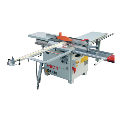
SICAR Group G3S 1500 Instruction and maintenance manual

Milwaukee
Milwaukee M12 2525-20 Operator's manual
Apex Tool Group
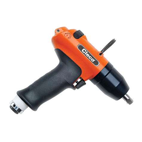
Apex Tool Group Cleco 80PTHH instruction manual
Scheppach
Scheppach HF60 Translation of original instruction manual
Dynaplug
Dynaplug Mini Pro Inflator GT quick start guide

Bavaria
Bavaria BMG 220 E Original operating instructions
