bITalino Mini Solo User manual

BITalino Mini User Manual
BITalino Mini
User Manual
PLUX –Wireless Biosignals, S.A.
Av. 5 de Outubro, n. 70 –2.
1050-059 Lisbon, Portugal
http://BITalino.com/
v.1.1
© 2020 PLUX
This information is provided "as is," and we make no express or implied warranties whatsoever with respect to functionality, operability, use, fitness for a
particular purpose, or infringement of rights. We expressly disclaim any liability whatsoever for any direct, indirect, consequential, incidental or special
damages, including, without limitation, lost revenues, lost profits, losses resulting from business interruption or loss of data, regardless of the form of action or
legal theory under which the liability may be asserted, even if advised of the possibility of such damages.
ATTENTION
Please read this datasheet before
using your BITalino sensor
The information contained in this document has been carefully checked and were made every
effort to ensure its quality. PLUX reserves the right to make changes and improvements to this
manual and products referenced at any time without notice.
The word Bluetooth and its logo are trademarks of Bluetooth SIG Inc. and any use of such
marks is under license. Other trademarks are the property of their respective own.
Please check your systems and sensors after receiving and before using it the first time to
confirm if it contains all the ordered sensors, accessories and other components. Contact our
For regulatory information, please see the Regulatory Disclaimer at the end of this document.

BITalino Mini
User Manual
3 of 24
TABLE OF CONTENTS
List of Figures ..................................................................................................................... 4
1. General Information..................................................................................................... 5
1.1. General Description ...................................................................................................... 5
1.2. Main Characteristics .......................................................................................................... 5
1.3. Features ............................................................................................................................ 6
1.4. Applications....................................................................................................................... 6
1.5. Sensors.............................................................................................................................. 6
2. Hardware layout and configuration................................................................................ 7
2.1. Block diagram.................................................................................................................... 7
2.2. Pinout diagram.................................................................................................................. 7
2.2.1. BITalino Mini Solo................................................................................................................. 7
2.2.2. BITalino Mini Shield .............................................................................................................. 9
2.3. Mechanical Drawings......................................................................................................... 9
2.4. LEDs ................................................................................................................................ 10
2.5. UART & BLE ..................................................................................................................... 10
2.6. SPI................................................................................................................................... 11
2.7. Jumper pads .................................................................................................................... 11
2.8. Power.............................................................................................................................. 11
2.8.1. Charging the BITalino.......................................................................................................... 12
2.9. Analog to Digital Converter.............................................................................................. 12
2.10. Enabling the digital channel UC-E6 port .......................................................................... 12
3. Using the BITalino Mini with OpenSignals .................................................................. 13
3.1. Configuring your device in OpenSignals (r)evolution (Windows, macOS, Linux).................. 13
3.2. Configuring the device in OpenSignals Mobile (Android)................................................... 15
4. Frequently Asked Questions........................................................................................ 18
5. Scientific Publications Using the BITalino .................................................................. 19
6. Safety & Maintenance ................................................................................................... 20
6.1. Safety Instructions........................................................................................................... 20
6.2. Transportation and Storage.............................................................................................. 21
6.3. Cleaning .......................................................................................................................... 21
7. Ordering Guides, Regulatory & Legal Information...................................................... 22
7.1. Ordering Guide................................................................................................................ 22
7.2. Guarantee of Quality & Warranty..................................................................................... 22
7.3. Warranty Voidance.......................................................................................................... 22
7.4. Contact & Support ........................................................................................................... 23
7.5. Regulatory Disclaimer...................................................................................................... 23

BITalino Mini
User Manual
4 of 24
List of Figures
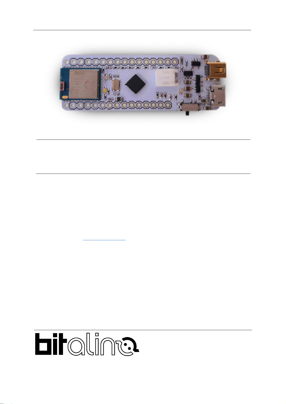
Figure 1 - BITalino Mini Solo ................................................................................................. 5
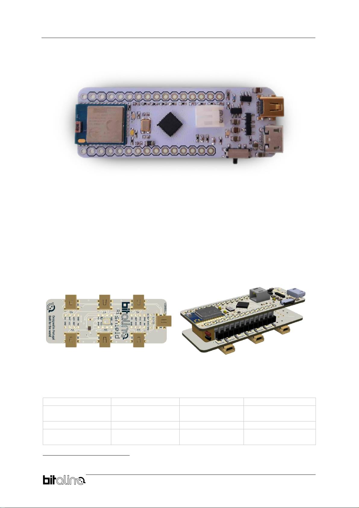
Figure 2 - BITalino Mini Shield............................................................................................... 5
Figure 3 - Block diagram ....................................................................................................... 7
Figure 4 - BITalino Mini Solo Top View.................................................................................. 7
Figure 5 - BITalino Mini Solo Bottom View............................................................................. 8
Figure 6 - BITalino Mini Solo Label Swap.............................................................................. 8
Figure 7 - BITalino Mini Shield Top View............................................................................... 9
Figure 8 - BITalino Mini Solo Dimensions in mm ................................................................... 9
Figure 9 - BITalino Mini Shield Dimensions in mm............................................................... 10
Figure 10 - How to enable the digital channel...................................................................... 12
Figure 11 - Access the OpenSignals (r)evolution device manager....................................... 13
Figure 12 - Enabling the device for acquisition .................................................................... 13
Figure 13 - Click the logo to open parameters..................................................................... 14
Figure 14 - Start the acquisition whenever you are ready.................................................... 14
Figure 15 - Home screen..................................................................................................... 15
Figure 16 Enable Bluetooth.............................................................................................. 15
Figure 17 Scanning for nearby devices............................................................................. 16
Figure 18 Devices found................................................................................................... 16
Figure 19 Device configuration......................................................................................... 17
Figure 20 - Example of acquisition with an ECG sensor...................................................... 17
BITalino Mini
User Manual
5 of 24
1. General Information
Figure 1 - BITalino Mini Solo
1.1. General Description
BITalino mini is a smaller version of our BITalino Core. Due to its small form factor, it is the
ideal toolkit for WearableDevelopment, OEM Solutions & Software App development. BITalino
Mini Solo device comes with one UC-E6 connector in one of the analog channels.
The user can also find useful handy tools, such as pinout headers allowing the easy connection
of the BITalino Mini Solo to a breadboard for electronic instrumentation procedures and sensor
development. To make more channels available as an out-of-the-box version, you can
upgrade your BITalino Mini SOLO by adding aBITalino Mini Shield (incl. pinout headers & UC-
E6 sockets) as shown in Figure 2.
1.2. Main Characteristics
> Sampling Rate
1, 10, 100, 1000Hz1
> Range:
Up to ~300m2
> Analog Ports:
4 in (10-bit), 2 in (6-
bit)
> Digital Ports:
2 in, 2 out
> PWM
1 out (8-bit)
> Communication:
BT/BLE, SPI, UART
> Microcontroller
ATMega328PB
(QFN)
> Consumption:
~34mA
1
BLE mode: 1000Hz only available when acquiring from one channel
2
Theoretical value under optimal conditions and in line of sight
Figure 2 - BITalino Mini Shield

BITalino Mini
User Manual
6 of 24
1.3. Features
>All-in-one ready-to-use design
>Small form factor
>On-board battery charger
>Affordable
>Raw data acquisition
>Easy-to-use
1.4. Applications
> Wearable development
> Bioengineering
> Electrical engineering
> Biofeedback
> Human-Computer Interaction
> Academic projects
> OEM solutions
> Biomedical engineering instrumentation
> Biomedical device prototyping
> Robotics & Cybernetics
> Physiology studies
> Hobbyists & Biosignals enthusiasts
1.5. Sensors
>Electromyography (EMG)
>Electroencephalography (EEG)
>Electrocardiography (ECG)
>Electrooculography (EOG)
>Electrodermal Activity (EDA)
>Electrogastrography (EGG)
For a full list of available and compatible sensors, please visit the BITalino store.

BITalino Mini
User Manual
7 of 24
2. Hardware layout and configuration
2.1. Block diagram
Figure 3 - Block diagram
2.2. Pinout diagram
2.2.1. BITalino Mini Solo
Figure 4 - BITalino Mini Solo Top View
BITalino Mini
User Manual
8 of 24
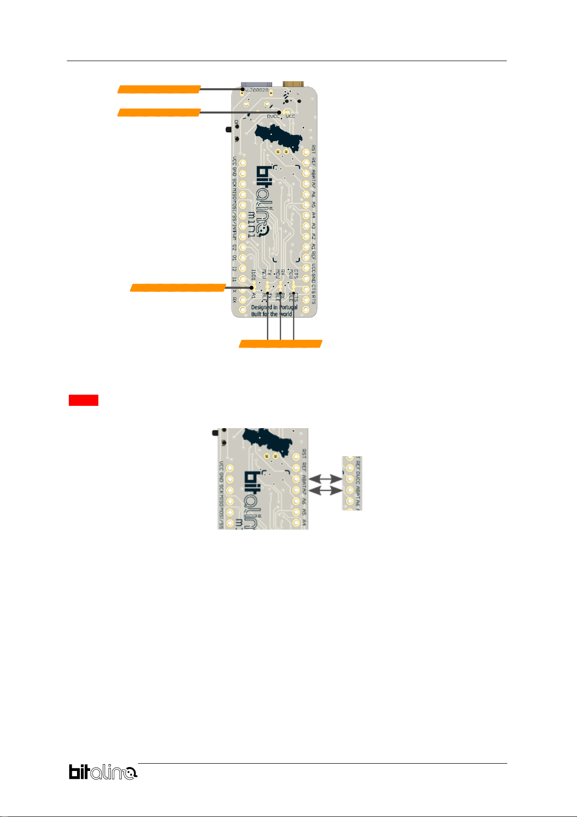
Figure 5 - BITalino Mini Solo Bottom View
NOTE: For devices with version number V.200828, ABAT
DVCC’ A7’ ABAT’.
Figure 6 - BITalino Mini Solo Label Swap

BITalino Mini
User Manual
9 of 24
2.2.2. BITalino Mini Shield
Figure 7 - BITalino Mini Shield Top View
2.3. Mechanical Drawings
Figure 8 - BITalino Mini Solo Dimensions in mm

BITalino Mini
User Manual
10 of
24
Figure 9 - BITalino Mini Shield Dimensions in mm
2.4. LEDs
The BITalino Mini
•Status LED: The status LED is the indicator of the two main
status in which you can find the BITalino system, idle or
acquisition. When you turn on the device the white LED will
turn on for 3 seconds and then it starts blinking slowly. This
means the system is currently in Idle mode and ready to
start an acquisition, at which point the LED will blink faster.
•LED 2 Battery status LED: The BITalino Mini was
designed to be a portable system and as such it is ready
to be powered by a 3,7V battery using its onboard JST
connector. The battery status LED was therefore added to
advert the user of a low battery level. By default, the LED will turn on solid orange
when the battery voltage reaches 3,4V. However, the firmware is ready to receive an
order to adjust this threshold. Such can be easily accomplished via one the many
3
website.
•LED 3 Charging status LED: There is no need to use
a third-party charger to charge the battery that powers
the BITalino. The device presents an onboard charger
that allows charging up the battery using a regular
Micro USB charging cable. The charging status LED turns on solid orange when the
device is charging, and it turns off once the battery is fully charged.
2.5. UART & BLE
By default, the BITalino Mini uses the UART protocol to send information to the onboard
Bluetooth Low Energy module to communicate wirelessly with other devices, such as a
3
https://bitalino.com/downloads/apis
Idle state
Acquisition state
Low battery
Good battery
level
Battery charging
Battery fully
charged

BITalino Mini
User Manual
11 of
24
computer where live data acquisition can be done with its dedicated software Opensignals
4
.
However, as mentioned above, the BLE Module can be virtually detached from the board to
enable direct communication between the MCU and an external device using the Tx and Rx
pins of the board. Either way, the information outputted by the MCU is set by default to the
following parameters:
- 1 Start bit
- 8 Data bits
- No parity bit
- 1 Stop bit
- 115200 Baud rate (0.2% error due to Baud Rate approximation)
- Double Speed Mode
By programming the firmware of the BITalino it isstill possible to set the UART communication
to any format resulting from a combination of the following characteristics:
- 1 start bit
- 5 to 9 data bits
- 1 optional parity bit (none, odd or even)
- 1 or 2 stop bits
- Single or Double speed mode
- Baud Rate up to 1.5Mbps
2.6. SPI
The BITalino Mini presents header holes connected to MISO, MOSI, SCK and SS to enable
the SPI communication protocol present on the ATMega328PB. However, the firmwareloaded
by default does not implement this functionality. It can be enabled by the user by modifying the
firmware made available on Github
5
. For more information on enabling the SPI peripheral,
please refer to the ATMega328PB datasheet
6
.
2.7. Jumper pads
On the back of the board five jumper pads can be found. These were implemented to enable
extra features of the device such as the communication through UART or the connection of a
digital sensor to the UC-E6 port.
1. Power Supply Jumper: Allows you to choose between the power supply dedicated to
the analog or digital circuits depending on the sensor you want to connect to the UC-
E6 port.
2. Analog/Digital Jumper: By default, the embedded UC-E6 port is connected to the
analog A1 channel. In order to plug a digital sensor into the UC-E6 port, cut
7
the
jumper pad connecting the A1 channel to it and solder the jumper to the I1O1 pad to
enable digital communication with the device via the UC-E6 port.
3. BLE/UART Jumpers: Cut these jumpers to virtually detach the BLE module from the
Microcontroller and enable communication with the MCU through UART
communication.
2.8. Power
The BITalino Miniwas designed to bepowered with a 3,7V Li-Po battery. To managethe power
distribution and prevent interferences between components, two independent voltage
4
https://bitalino.com/downloads/software
5
https://github.com/BITalinoWorld/firmware-bitalino-revolution
6
https://ww1.microchip.com/downloads/en/DeviceDoc/40001906C.pdf
7
See chapter 2.10 - Enabling the digital channel UC-E6 port for more information

BITalino Mini
User Manual
12 of
24
regulators are used to power the analog and the digital components of the device at 3.3V, VCC
and DVCC.
2.8.1. Charging the BITalino
The BITalino Mini has a built-in charging circuit designed to safely chargeup the Li-Po batteries
that it uses. To charge the battery, connect the micro-USB cable provided with the BITalino
Mini to the micro-USB port of the board and plug it to any USB 5V port. Note that the BITalino
must be turned OFF for the battery to charge. It takes about 1h to charge the BITalino Mini
standard 240mAh battery.
2.9. Analog to Digital Converter
The BITalino Mini uses the Analog to Digital Converter (ADC)embedded in the ATMega328PB
Microcontroller unit with the following characteristics:
•10-bit resolution
•8 channels
•±2LSB Absolute Accuracy
•0 - VCC ADC Input Voltage Range
Its embedded firmware however exploits this peripherical in such a way that it allows up to 6
analog channels in acquisition with the following configurations:
•6 Analog channels acquiring:
o10-bit resolution for channels A1 to A4.
o6-bit resolution for channels A5 and A6.
•5 Analog channels acquiring:
o10-bit resolution for the first 4 channels.
o6-bit resolution for the last channel.
•4 or less Analog channels acquiring:
o10-bit resolution in every channel.
2.10. Enabling the digital channel UC-E6 port
The BITalino Mini Solo has one built-in UC-E6 port connected by default to analog channel
A1. This allows to connect all the variety of analog sensors available for the BITalino devices.
In case you want to connect a digital sensor, you will have to make use of the jumper pads
on the back of the board to
activate the digital channel I1/O1 and change the power source that supplies the UC-E6 port.
Using a hobby knife, cut the pads that connect the power to VCC and the channel to A1. Then,
apply some solder to the pads DVCC and I1O1 to connect them to the UC-E6 port. By doing so,
you will be able to connect a digital sensor to the channel I1O1 powering it the power supply
dedicated to digital sensors.
Figure 10 - How to enable the digital channel

BITalino Mini
User Manual
13 of
24
3. Using the BITalino Mini with OpenSignals
3.1. Configuring your device in OpenSignals (r)evolution (Windows,
macOS, Linux)
To configure your device in OpenSignals (r)evolution start by switching it on and opening the
software in your computer. Open the device manager of Opensignals to access and configure
your BITalino device.
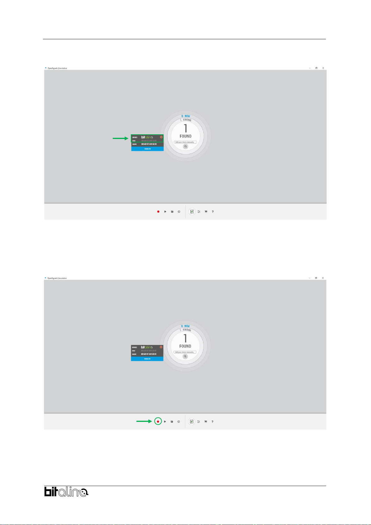
Figure 11 - Access the OpenSignals (r)evolution device manager.
If the deviceis turned onand in range, it should appear after afew seconds. Inthe configuration
window you can select which channels to visualize, how to display the data and the sampling
frequency.
Figure 12 - Enabling the device for acquisition
BITalino Mini
User Manual
14 of
24
If the configuration window does not appear automatically, simply click on the BITalino logo to
access it.
Once every setting is as desired, make sure the device is activated and the acquisition can
start. The device is activated for acquisition if the ENABLE button is blue. Click on the record
button in the OpenSignals main interface whenever you are ready for your acquisition.
Figure 13 - Click the logo to open parameters
Figure 14 - Start the acquisition whenever you are ready
BITalino Mini
User Manual
15 of
24
3.2. Configuring the device in OpenSignals Mobile (Android)
The Opensignals (r)evolution software is also available for Android devices and it can be
download from Google Play Store
8
for free. To use your BITalino Mini with your mobile device
start by installing the android application and opening it.
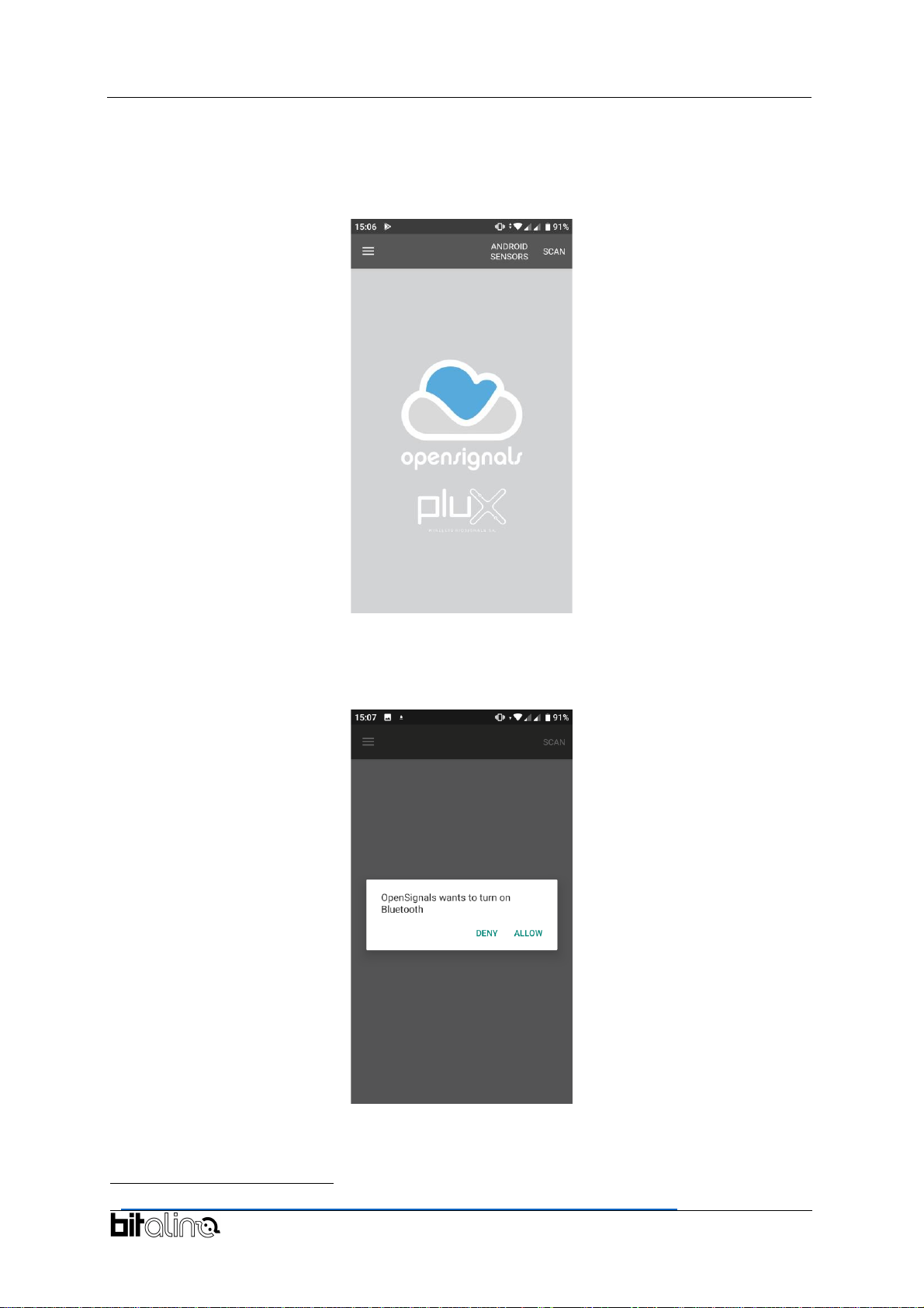
Figure 15 - Home screen
Turn on do not have your Bluetooth
connection already enabled, the application will prompt you to enable it.
Figure 16 Enable Bluetooth
compatible with the application.
8
https://play.google.com/store/apps/details?id=info.plux.opensignalsmobile

BITalino Mini
User Manual
16 of
24
Figure 17 Scanning for nearby devices
Any compatible device that is turned on and in range will appear on the main screen
displaying its MAC address. Select the one you want to connect to configure its settings and
start the acquisition.
Figure 18 Devices found
In the configuration screen you can select the sampling rate, the channels to acquire, the data
type, the visualization channels, among others.

BITalino Mini
User Manual
17 of
24
Once all the settings are as desired, click on the record button on the top right corner to start
the acquisition.
Figure 20 - Example of acquisition with an ECG sensor
Figure 19 Device configuration

BITalino Mini
User Manual
18 of
24
4. Frequently Asked Questions
?
Can I program the BITalino?
Yes. You can write your code in C and upload it to the micro-controller using an AVR
ISP programmer; you can also upload the Arduino bootloader onto the board.
Nonetheless, giventhat all the sensors and peripheral on BITalino are general-purpose,
it may be easier to replace the BITalino MCU by an Arduino or another 3rd party system.
?
What is the battery lifetime?
The BITalino Mini can last up to 5h acquiring with its standard battery (240 mAh),
although BITalino is compatible with any JST PHR-2 terminated 3.7V battery enabling
you to easily extend the lifetime.
?
Can I communicate with the BITalino using other interfaces besides bluetooth?
Yes. BITalino has the UART port fully exposed, which means that you can replace the
Bluetooth interface by any UART-
Furthermore, by programming your own firmware, you can also make use of the SPI
port.
?
Are the BITalino accessories compatible with other devices?
BITalino accessories can be connected to any third-party devices that can provide a 0-
3.3 V power supply and that can deal with the analog outputs of the sensors.
?
Can I connect third-party sensors to BITalino?
Provided that your accessories have power and analog output specifications compatible
with those of the BITalino hardware you can connect any sensor and even your own
custom designs. You can also connect 1-bit digital input or output accessories (e.g.
switch).
?
Can I create a wearable device for body signal monitoring?
Yes. You can either use the BITalino blocks that are available in our webstore as
individual components or use our BITalino (r)evolution mini. Alternatively, if you think
your project needs a partner and R&D collaboration you can always ask for our services
?
Does the MCU make any type of filtering or signal conditioning?
No. The only signal conditioning done at the hardware level is made on the analog front
end of each sensor. All the inputs & outputs on the MCU are general purpose and
unconditioned.
?
Can I use the BITalino while charging its battery?
No. The BITalino was designed to charge only when turned off. For your safety, you
should not attempt to use it with a charger plugged.
?
Is the sampling rate (e.g. 1KHz) per channel or shared between the acquired
channels?
The sampling rate on BITalino is per channel and not shared. For example, if the
acquisition is performed at 1KHz (or any of the other options for what matters), each
channel is sampled at the chosen rate regardless of the number of channels acquired.
?
Can the sampling rate be independently set for each channel?
In order to improve the ease-of-use of the software and APIs, we chose to have all the
channels sampled at the same sampling rate.

BITalino Mini
User Manual
19 of
24
5. Scientific Publications Using the BITalino
The following scientific is only a small selection extracted from the list of available publications
using BITalino. Please visit the following website to access the entire up-to-date list:
https://bitalino.com/en/community/publications
Publications
Diana Batista, Hugo Plácido da Silva, Ana Fred, Carlos Moreira, Margarida Reis, Hugo
against an established
-36, April 2019
Pedro Morouço, Joana Pinto, Eduardo Félix, Paulo Correia and Hugo Plácido da Silva,
-
Biomechanics in Sports, pp. 1-4, 2020
Roberta Bortolla, Marco Cavicchioli, Joaquim Soler Rivaldi, Juan Carlos Pascual Mateos, Paul
Psychology, 8(1), pp. 1-17, 2020
Nuzhat
in Bioengineering, 7(1), pp. 16, 2020
Daniel de la Iglesia, André Mendes, Gabriel González,Diego Jiménez-Bravo and Juan de Paz
Connected Elbow Exoskeleton System for Rehabilitation Training Based on Virtual Reality and
Context-
Andrea Lorena, Aldana Blanco, Marian Weger, Steffen Grautoff, Robert Holdrich and Thomas
ation of Heart Sounds
Workshop (iSon), pp. 115-122, 2019
Analysis Based on Intern
TELKOMNIKA Telecommunication, Computing, Electronics and Control, 18(3), pp. 1406-
1415, 2020
Vanessa Georges, François Courtemanche, Marc Fredette and Philippe Doyon-Poulin,
Conference on Human Factors in Computing Systems, pp. 1-8, 2020
Fábio Mendonça, Sheikh Mostafa, Fernando Morgado-Dias and Antonio Ravelo-
Oximetry Based Wireless Device for
MDPI Applied Sciences, 10(3), pp. 911, 2020

BITalino Mini
User Manual
20 of
24
6. Safety & Maintenance
6.1. Safety Instructions
Please read the following safety instructions before using your BITalino system with the EDA
sensor to prevent any damages or problems with the user, test persons and/or BITalino
devices. Violations of these instructions can lead to inferior signal quality and/or damages to
the BITalino system and user.
!
The user should always keep the device and its accessories dry.
!
The user must turn off the BITalino device and contact Technical Support if the system
or accessories reach uncomfortable temperatures.
!
The user should not use the BITalino device in noisy environments (environments with
microwaves and other similar equipment). Doing so will lead to noise increase in the
acquired signals and Bluetooth connectivity issues.
!
The user must not use the device near the fire or in potentially explosive atmospheres,
such as atmospheres with flammable gas.
!
The user should only use the detection surfaces or other approved accessories
purchased from PLUX or by a PLUX agent.
!
The user should inspect the sensors on a regular basis to ensure that they remain in
good working order.
!
The user should stop using the BITalino device if experience any kind of discomfort or
skin irritation.
!
Do not use the system on persons with allergies to silver.
!
The user should dispose detection surfaces after using the BITalino device. Detection
sur- faces are single-user and disposable. Reusable electrodes should be reused by
the same user. Do not use reusable electrodes on several users.
!
The user must not place the device in the microwave.
!
The user must not insert objects into the holes of the device.
!
The user should not open the BITalino device or its accessories. The repair of the same
should be only done by properly authorized PLUX personnel.
!
The user should make sure the cables do not obstruct the passage of people.
!
The user should use the sensor cables with extreme caution to avoid risk of
strangulation.
!
The user should keep a safe distance between the BITalino device and other devices
to ensure their proper functioning.
!
The user should only send the device to repair to qualified PLUX personnel.
This manual suits for next models
1
Table of contents
Other bITalino Accessories manuals


