Bitron AC Wall SOCKET User guide

STAZIONI DI RICARICA
AC Wall SOCKET & PLUG
INSTALLER'S MANUAL
for cable and socket versions
Instruction Manual:
09004870

AC WALL Socket & Plug – Installation Manual
1 / 57
EN
INDICE
1INTRODUCTION ............................................................................................................................................................. 3
1.1 Manual Purpose....................................................................................................................................................... 3
1.2 Application fields .................................................................................................................................................... 3
1.3 Exclusion of responsibility ................................................................................................................................... 4
1.4 Warranty................................................................................................................................................................... 4
1.5 Assistance Service.................................................................................................................................................. 5
1.6 Symbols..................................................................................................................................................................... 5
2SAFETY............................................................................................................................................................................. 6
2.1 General requirements ............................................................................................................................................ 6
2.2 Specific requirements............................................................................................................................................ 7
3PRODUCT PRESENTATION ....................................................................................................................................... 9
3.1 General features...................................................................................................................................................... 9
3.2 Main technical specifications..............................................................................................................................10
3.3 Identity labels..........................................................................................................................................................12
4PRELIMINARY INFORMATION................................................................................................................................13
4.1 Unpacking ................................................................................................................................................................13
4.2 Package contents...................................................................................................................................................14
4.3 Required tools.........................................................................................................................................................14
5PRE-REQUISITE ............................................................................................................................................................15
5.1 Positioning...............................................................................................................................................................15
5.2 Repositioning..........................................................................................................................................................16
5.3 General electrical requirements .........................................................................................................................17
5.4 External protections required.............................................................................................................................18
5.5 Power cables...........................................................................................................................................................19
6INSTALLATION PROCEDURES ............................................................................................................................. 20
6.1 Opening the device................................................................................................................................................21
6.2 Wall mounting .......................................................................................................................................................22
6.3 Basic electrical installation.................................................................................................................................23
6.3.1 Inserting the power cables....................................................................................................................23
6.3.2 Single-phase power supply..................................................................................................................24
6.3.3 Three-phase power supply...................................................................................................................25
6.3.4 Cable version specificities.....................................................................................................................26
6.4 Current selector.....................................................................................................................................................27
6.5 Wired communication options ..........................................................................................................................28
6.5.1 RS485 multiple connection and “Power Sharing”..........................................................................29
6.5.2 External AT................................................................................................................................................ 31
6.5.3 External MID METER..............................................................................................................................32

AC WALL Socket & Plug – Installation Manual
2 / 57
EN
6.5.4 Ethernet .....................................................................................................................................................33
6.5.5 Chain 2 connection (only for Italy)......................................................................................................33
6.5.6 TIC connection (only for France).........................................................................................................34
6.6 Wireless communication ....................................................................................................................................34
6.6.1 BLE (Bluetooth) and Wi-Fi Connections...........................................................................................34
6.6.2 4G/LTE mobile network connection ..................................................................................................34
6.6.3 RFID connection.......................................................................................................................................35
6.7 Closing operations................................................................................................................................................35
7CONFIGURATION and ACTIVATION ....................................................................................................................37
7.1 Installer's luminous interface.............................................................................................................................37
7.2 First time switching ON.......................................................................................................................................39
7.3 Configuration using the Installer's APP ......................................................................................................... 40
7.4 BLE (Bluetooth) communication .......................................................................................................................41
7.5 Wi-Fi Communication ..........................................................................................................................................41
7.6 Mobile (4G/LTE) communication.....................................................................................................................42
7.7 RFID authentication .............................................................................................................................................42
7.8 Other types of communication..........................................................................................................................42
7.9 Electrical parameters configuration.................................................................................................................43
7.10 Reinstating default configuration.....................................................................................................................43
8USE and USER INTERFACES................................................................................................................................... 46
8.1 User luminous interface ..................................................................................................................................... 46
8.2 Use............................................................................................................................................................................47
8.3 “Ready-To-Charge” function ............................................................................................................................ 48
8.4 User’s APP............................................................................................................................................................. 49
9MAINTENANCE ........................................................................................................................................................... 50
9.1 Ordinary maintenance........................................................................................................................................ 50
9.2 Extraordinary maintenance ................................................................................................................................51
10 DECOMMISSIONING ...................................................................................................................................................52
10.1 Prescriptions and symbols .................................................................................................................................52
10.2 Preparation for disposal......................................................................................................................................53
10.3 Particular cases .....................................................................................................................................................53
11 ADDITIONAL INFORMATION................................................................................................................................. 54
11.1 Certifications and Declarations of Conformity ............................................................................................. 54
11.2 Spare parts ............................................................................................................................................................ 54
11.3 Accessories ............................................................................................................................................................55
11.4 Glossary and terminology.................................................................................................................................. 56

AC WALL Socket & Plug – Installation Manual
3 / 57
EN
1 INTRODUCTION
This document is exclusively the property of BITRON who holds all rights to the same. Any other
trademarks or trade names of products referred to herein, belong to their respective owners.
In no circumstances may this manual be copied, amended, reproduced, translated, or distributed in
any form, whether complete or partial, without prior authorisation in writing.
BITRON reserves the right to make any change to this document and to the products it describes, at
any time and without prior notice.
The latest version of this manual and other additional documentation can be downloaded by scanning
the QR-Code(s) on the last page of this document or via the website “https://www.bitron.com/en/ev-
charging-user-documents”.
1.1 Manual Purpose
This manual provides all the useful information for installing, configuring, and preparing use of the
AC charging devices range in complete safety. It also provides basic information for using the station
for the first time as well as for routine and extraordinary maintenance.
BITRON regularly checks and updates the information provided here to make it easier to understand
and to reduce the risks of mistakes during installation. Any discrepancies must be reported timeously
to the relevant After-Sales Department.
1.2 Application fields
This Manual refers only to electric vehicle charging devices classified in terms of the IEC 61851-1
standard, which identifies its technical and functional characteristics.
The information and procedures provided only apply to the range of products called “AC Wall
SOCKET” and “AC Wall PLUG”, and do not refer to any other device not expressly mentioned below:
AC Wall SOCKET / 1F-7,4KW / BASE, and series variants
AC Wall SOCKET / 3F-22KW / BASE, and series variants
AC Wall PLUG / 1F-7,4KW / BASE, and series variants
AC Wall PLUG / 3F-22KW / BASE, and series variants
The variants of each model are generated by the inclusion of optional devices or versions with
specific configurations, of which the main ones are listed below:
→Inclusion of the Ethernet board
→Inclusion of the reading module for RFID and any Cards and Keys provided
→Inclusion of a 4G/LTE Modem
→Availability of an auxiliary RS485 port for managing “Power Sharing”
→CHAIN 2 configuration (specifically for Italy)
→TIC Linky configuration and related accessories (specifically for France)

AC WALL Socket & Plug – Installation Manual
4 / 57
EN
This manual is intended exclusively for suitable qualified technicians who hold a qualification for
appropriate training issued by the relevant Body in the Country in which they work, in accordance
with local regulations and requirements in force on the date of installation.
The installer must have adequate knowledge of how electrical equipment and civil electrical
equipment function and are maintained, as well as of the relevant current norm and responsibilities
deriving from the work they do.
1.3 Exclusion of responsibility
The information provided in this manual has been carefully checked by BITRON, to the best of
their knowledge. Nevertheless, BITRON does not explicitly or implicitly guarantee the precision,
completeness, and total reliability of the same.
BITRON does not accept any responsibility for any direct or indirect damage caused to third
parties and property (including the product itself) deriving from or related to incorrect
interpretation or use of the information contained in this manual.
BITRON does not accept any responsibility for any direct or indirect damage caused to third
parties or property, in the widest sense of the word, deriving from or related to incorrect
installation or incorrect commissioning of the device by the operator.
BITRON is not responsible for malfunctioning of the (mechanical and electrical) installation of
their product, its performance or functionality, once put into operation and configured by the
installer for the specific existing infrastructure. BITRON is also not responsible for the proper
functioning and conformity of plants upstream and downstream of their product.
BITRON cannot be held responsible for defects or malfunctioning resulting from:
-Installation by personnel who are not suitably qualified.
-Improper use of the unit and failure to follow the usage instructions.
-Incorrect or insufficient maintenance.
-Tampering, modification, or repairs that do not conform to the instructions.
-Deterioration due to transportation or unspecified environmental conditions.
-
BITRON is also not responsible for disposal of the unit or part thereof. Disposal must be done
strictly in accordance with the most up-to-date norms and laws in force in the Country in which
the unit is installed.
1.4 Warranty
The “AC WALL Socket” and “AC WALL Plug” charging stations series are covered by a legal warranty
for 24 months from the date of delivery, in conformity to the provisions of the European Norm in force
on the date this manual was drawn up. The duration and conditions of the legal warranty may vary
depending on how the destination Country assimilates and integrates the legislative requirements of
the European Community into its own directives.
Where called for, the details of the warranty are indicated in the product General Sales Contract, and
can be the subject of specific supply agreements.
AC WALL Socket & Plug – Installation Manual
5 / 57
EN
BITRON reserves the right to reject the warranty conditions in all the cases mentioned in the
"Exclusions of Responsibility" sub-chapter, without any exception. Specifically, BITRON may not be
held responsible for defects and/or malfunctioning of the charging station, vehicles being charged,
and electricity supply, should even only one of the following conditions apply:
-Installation by personnel who are not suitably qualified.
-Failure, even partial, to abide by the installation instructions and recommendations.
-Improper use of the unit and failure to follow the usage instructions.
-Incorrect or insufficient routine and/or extraordinary maintenance.
-Tampering, modification, work, or repairs that do not conform to the instructions.
-Deterioration due to transportation or unspecified environmental conditions.
1.5 Assistance Service
BITRON provides a highly qualified Assistance Service for the specific Country of destination, in order
to assist the Installer in their tasks. The contact details to be used are given on the last page of this
manual, on which the QR-Code is also shown, to be used to download and obtain all useful
documentation.
1.6 Symbols
Please pay particular attention to the symbols used, as these highlight the most sensitive topics in
terms of safety, care required, and the risk related to individual procedures. The symbols also provide
additional information indispensable for correct understanding.
DANGER – Indicates a medium to high generic risk to people, animals, or property. Failure
to respect these procedures may give rise to:
-Serious or fatal injuries to people and animals, during installation and use.
-Irreparable damage to the charging station, infrastructure, and items in the vicinity.
-Risks of electric discharges, fire, or other significant collateral damage.
ATTENTION – Indicates a potential situation of risk to people, animals, or property. Failure
to abide by the instructions may give rise to:
-Injuries to people and animals, during installation and use.
-Damage to or malfunctioning of the charging station and the infrastructure.
-It being impossible to use all the available functions.
CORRECT – Indicates the correct action to be taken or correct scenario, as showed by the
procedure described in this manual.
WRONG – Indicates a wrong operation or scenario, to be avoided to prevent generic dangers
or malfunctions of any kind.
INFORMATION – Provides information in addition to the procedure described, including
specific suggestions and notes of general interest.

AC WALL Socket & Plug – Installation Manual
6 / 57
EN
2SAFETY
Safety is an essential element to be considered carefully, in all stages of installing the charging
station. This chapter provides a detailed list of all situations that may give rise to a medium or high
risk to the safety or people, animals, or property during installation, day-to-day use, and maintenance
of the device.
2.1 General requirements
The general information below applies to all the procedures and instructions described in this
installation manual. Without exception, they must be deemed to be essential for safe, workman-like
installation, as recommended by the charging station manufacturer.
A. Installation must only be carried out by suitable qualified technicians who hold a
qualification for appropriate training issued by the relevant Body in the Country in
which they work, in accordance with local regulations and requirements in force on the
date of installation.
B. The installer must have adequate knowledge of how electrical equipment and civil
electrical equipment function and are maintained, as well as of the relevant current
norm and responsibilities deriving from the work they do.
C. This manual and related documentation must be read carefully, understood correctly,
and interpreted according to the context in which the charging station is installed or
used. The instructions provided must always be strictly applied.
D. Installation must be done in conformity to the norms in force in the destination country
on the date the work is done, and in accordance with all the safety rules called for in
relation to electrical works. Type approved personal protective equipment must be
used, as called for by local legislation and by any additional procedures drawn up, and
must be applied by the individual Companies to which the technician belongs or for
which they do the work.
E. The installer has the duty of informing the user that they are not authorised in any
circumstances to carry out routine or extraordinary maintenance or repairs on the
charging station, even if these are minor tasks. The user is also not authorised to open
the unit, modify any component(s), reposition them, or work on the electrical system it
is connected to (including wired connections to any external devices).
F. Any person who is not capable of assessing the risks associated with using the charging
station (including children) must not be authorised to use the unit, and must be
supervised when in the vicinity. Keep any domestic animals away from the device, even
when no charging is taking place.

AC WALL Socket & Plug – Installation Manual
7 / 57
EN
2.2 Specific requirements
The safety information below, broken down into two risk levels, relate specifically to the operating
notions and procedures for installation, use, and maintenance. Where of use, these will be repeated
and detailed in the chapters that describe specific tasks.
We wish to stress that the installer must inform the user of the risk that may arise from not knowing
and abiding by the information below.
A. The charging station is designed exclusively for charging compatible electric vehicles
that do not require ventilation while charging. In no circumstances must it be used for
other purposes, modified even partially, or integrated into electrical systems for
different or complementary purposes.
B. Before and during installation and use of the charging station, check that its parts are in
good condition. Never install or use a device that has clearly visible damage or defects,
especially to the plastic parts, cables, or connectors.
C. Always inform the user that if the charging station is damaged after installation, it is
essential that the electricity supply to it be interrupted immediately, using the relevant
switch on the electrical panel. Before using it again, always have work done on it by a
specialist technician.
D. Do not disassemble the charging station and do not install it outdoors when there is rain,
snow, or hail, when there is severe humidity, or at temperatures outside the operating
range (from -30°C to +50°C).
E. Never install the unit on walls that are mobile or semi-mobile, flammable, or clad in
flammable material, adjacent to passageways or emergency exit routes, with plumbing
or gas plants even if not flammable.
F. Also make sure that there are no excessive heat or electromagnetic sources, highly
flammable or explosive materials in the vicinity of the charging station. Make sure that
these recommendations are also applied to the charging cables that are often subjected
to damage and wear.
G. Do not immerse the connectors in liquids of any kind and avoid exposing the charging
station of direct or any strong water jets. (For instructions on washing the surfaces, see
the "MAINTENANCE" chapter).
A. The charging station is designed for indoor or outdoor use, in accordance with the criteria
laid down by the current norm. Despite this, we advise against using it in heavy rain or
when directly exposed to bad weather. Before use, always check that the connectors
(including that on the vehicle side) are not wet, too damp, or dirty.
B. Handle the charging cable carefully, avoiding pulling it with excessive force, and
protecting it against tears, impacts, and abrasion. Always grip the connector, without
pulling on the cable. When charging is complete, wind the cable in the relevant support
or, if it is removable, put it where it is protected against damage.

AC WALL Socket & Plug – Installation Manual
8 / 57
EN
C. The models of the charging stations with cables have a standard Type-2 connector,
which is compatible with most vehicles on the market. If the connector is not compatible
with your vehicle, please contact the Manufacturer's Assistance Department, to identify
the correct adapter. Using adapters, extensions, and accessories that do not conform or
are not type-approved, can give rise to malfunctions or irreversible damage to the unit.
D. Disposal of the charging station and its parts must be done in accordance with the
provisions of the norm in force in the Country in which it operates. In any case, it must
be disposed of as waste from electrical / electronic equipment (WEEE) separately from
domestic waste. For more details, see the "DECOMMISSIONING" chapter in this manual.
AC WALL Socket & Plug – Installation Manual
9 / 57
EN
3PRODUCT PRESENTATION
The purpose of this chapter is to provide an overall view of the product. It therefore does not indicate
the physical characteristics, technical specifications, and main functions. Further details are available
in the chapter on installation procedures.
This information may be amended frequently, due to ongoing improvement of the products
it refers to, and evolution of the reference norms. The images are merely explanatory and
may not be identical to the product.
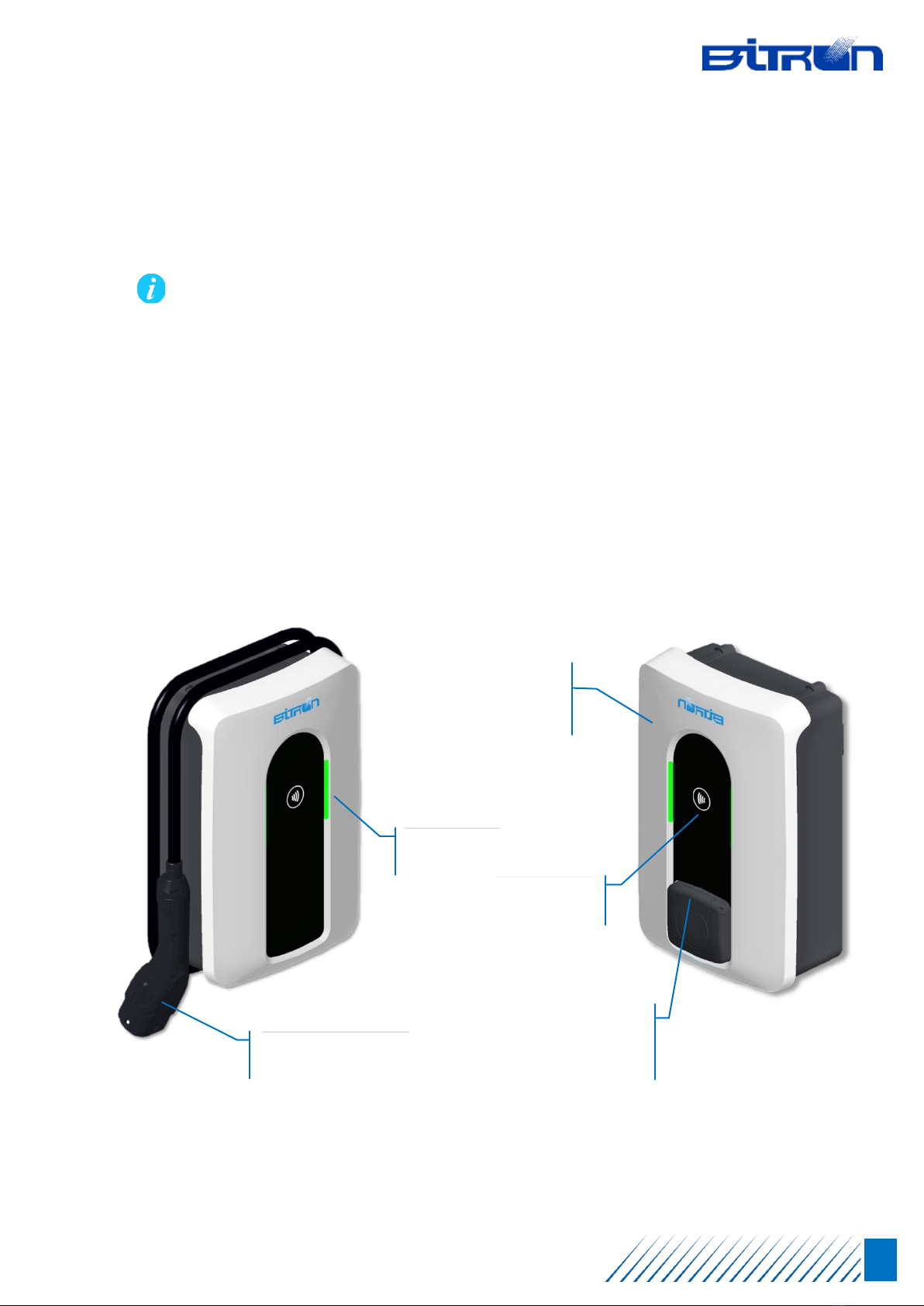
3.1 General features
“AC WALL Socket” and “AC WALL Plug” series charging stations are alternating current solutions for
electric or hybrid rechargeable vehicles that have a standard Type-2 connector. The charging mode
is type 3, in accordance with the IEC 61851-1 standard. They are intended for private or semi-private
residential use (condominiums, housing clusters, etc.) and semi-public use (companies, small /
medium groups, etc.).
Depending on the model, it can be connected to single-phase electrical network, with a maximum
charging power up to 7,4 kW, or to three-phase supplies, with a maximum power up to 22 kW.
AC Wall PLUG
Models with cable
AC Wall SOCKET
Models with socket
5
metre cable with
Type-2 connector
Type-2
socket
with
motorized
s
hutter
RFID
r
eader
LED (x2)
i
nterface
Removable
f
ront
p
annel

AC WALL Socket & Plug – Installation Manual
10 / 57
EN
The charging stations must be connected to the electricity grid permanently, have Class I protection
against electric shocks, have a Class B EMC environmental index, and do not support the optional
function of ventilation during charging.
All the charging stations offer high level of connectivity as a standard feature, which allows remote
control or simple monitoring via a dedicated App. For models fitted with a specific electronic board, a
connection can also be performed via a 4G mobile network or a wired data network.
The interfacing with a series of external devices is also possible to provide additional or
complementary functions to simple vehicle charging.
3.2 Main technical specifications
The table below shows the product's main technical features. Further details can be downloaded by
scanning the QR-Code(s) on the last page of this document.
ELECTRICAL SPECIFICATIONS
AC WALL SOCKET range / Charging Mode
AC WALL PLUG range / Charging Mode
Type 2 + Shutters / Mode 3
Type 2 Gun + Harness 5 m / Mode 3
Single Phase Nominal Voltage / Max Power
230 Vac 50 Hz / up to 7,4 kW
Three Phase Nominal Voltage / Max Power
400 Vac 50Hz / up to 22 kW
AC Connection System
TT and TN
DC Residual Current Protection RCCB by GFCI
6mA / 30mA r.m.s.
Energy Meter
Built-in (Not MID)
Power Configuration Selector Embedded
CONNECTIVITY AND INTERFACES
Bluetooth (BLE) or Wi-Fi
Mutually exclusive
4G (3G not available)
Internal LTE modem
Ethernet LAN Standard Port
RJ45
External Energy Meter Interface RS-485 MODBUS
OCPP Protocol
JSON 1.6
Power Line Communication
PLC CHAIN2
RFID Reader
NFC, MIFARE, NDEF reading
Visual Interface
Color-coded RGB LEDs
OPERATION AND STANDARDS
Operating Temperature Range
-30°C to +50°C
Operating Humidity Range
<95% (Not Condensing)
Operating Altitude Limit
2000 meters a.s.l.
Ingress Protection Rating
IP55 (indoor and outdoor use)
Mechanical External Impacts Protection Rating IK08
Standards
IEC62196, IEC61851, IEC62955, ISO15118
Certification
CE 2023
AC WALL Socket & Plug – Installation Manual
11 / 57
EN
ADDITIONAL RELEVANT FEATURES
Data Encryptions
Embedded ECB Protocol
Alternative Energy Sources Management
Via external TA (Amperometric Transformer)
Remote SW/FW Update
LAN, 4G, Wi-Fi or Bluetooth)
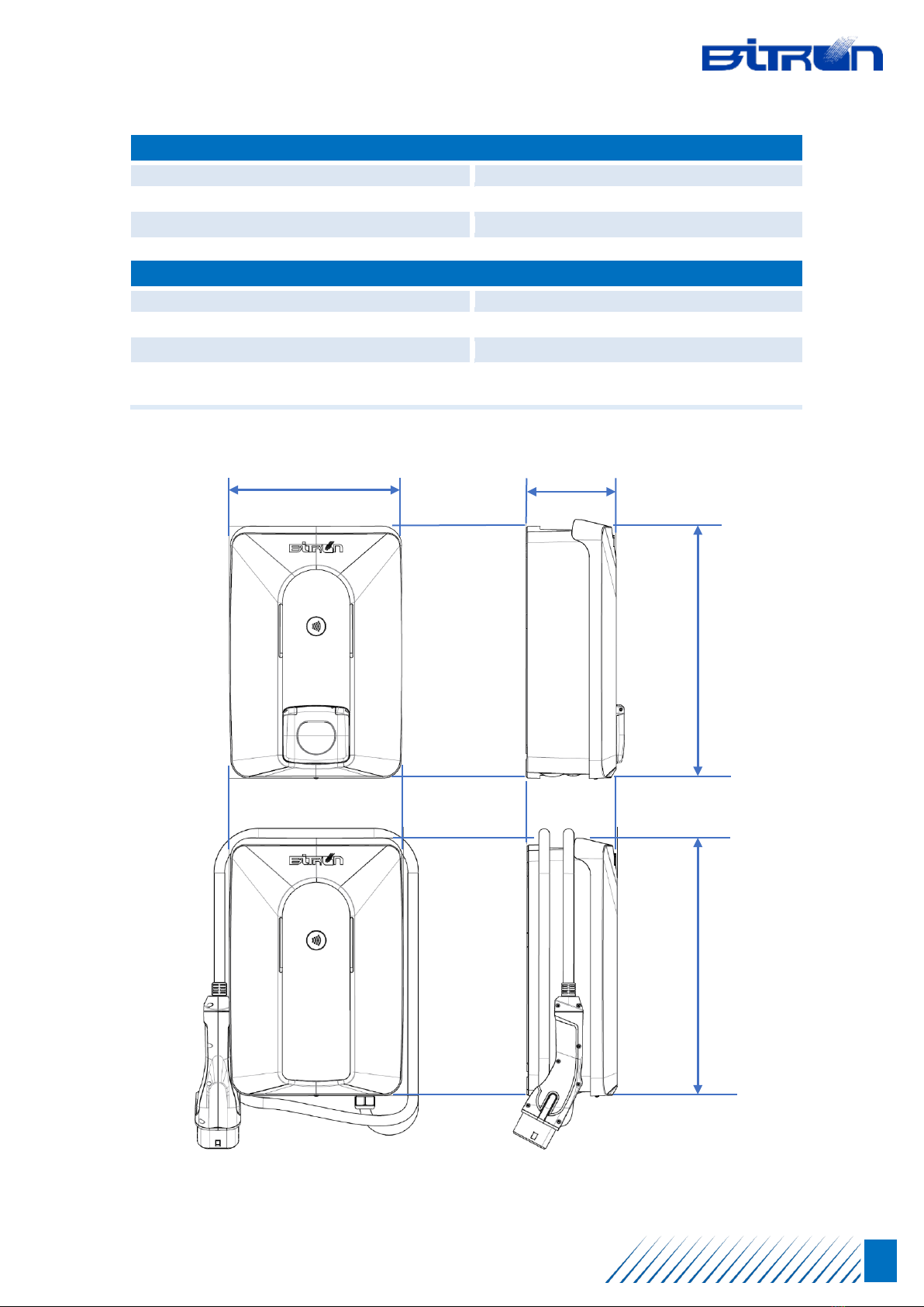
MECHANICAL
Housing Material
Polycarbonate
Wall Mounting
3 fixation points by screws
Installation Environment
Indoor or Outdoor
Dimensions Excluding Harness (L x W x H)
(Excluding Harness for Harness versions)
390 x 265 x 135 mm
15,4 x 10,4 x 5,3 in
390 mm
265 mm
135 mm
390 mm
AC WALL Socket & Plug – Installation Manual
12 / 57
EN
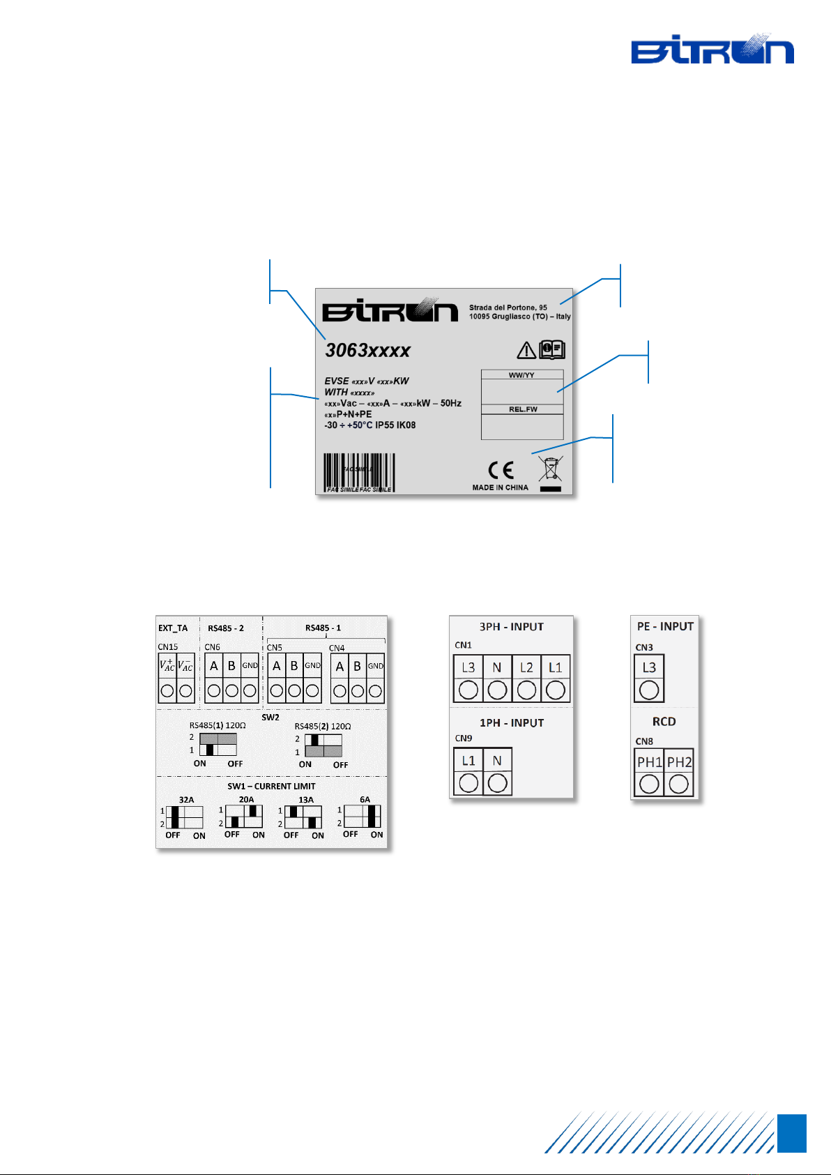
3.3 Identity labels
A series of labels are applied to the unit, showing the data related to the product, as well as providing
the main references for the electrical connection.
PRODUCT LABEL
External positioning
ELECTRICAL CONNECTION LABELS
Internal positioning
A product label is also applied to the cardboard packaging to allow precise identification of the content
(version, model, accessories, configuration, etc.).
Other labels indicate the specific reference norm for the parts that make up the unit, such as the
connector.
Manufacture’s
identity
Model
identification
Symbols related to
international
standards
obligations
Traceability
information
Model
Version
Po
wer supplied
T
ype of power
Operating
data
AC WALL Socket & Plug – Installation Manual
13 / 57
EN
4PRELIMINARY INFORMATION
We strongly recommend getting to know the preliminary phases described in this chapter. This will
make it possible to avoid slip-ups or errors that may have a direct effect on the installation process,
extending the times or introducing problems that then have to be corrected as the work proceeds.
4.1 Unpacking
The charging station comes in specific, robust packaging that provides good protection during
transportation, storage, and all the handling operations required.
All the packaging materials can be recycled in accordance with the specific procedures applied in your
Country. The cardboard parts are also FSC (Forest Stewardship Council) certified, which attests to
BITRON's care for the environment and the subsequent Socio-Economic aspects.
Before opening the package visually check that it has not already been opened, that it is not
damaged, and that it has not been in contact with any liquids. If you have any doubts as to
the integrity of the contents, we recommend contacting the relevant Assistance Service.
Keep the original packaging for possible future moving (such as possible repositioning) and
ensure that it is stored correctly. BITRON is not responsible for any damage caused in transit,
and reserves the right to reject any return not packed in the original packaging.
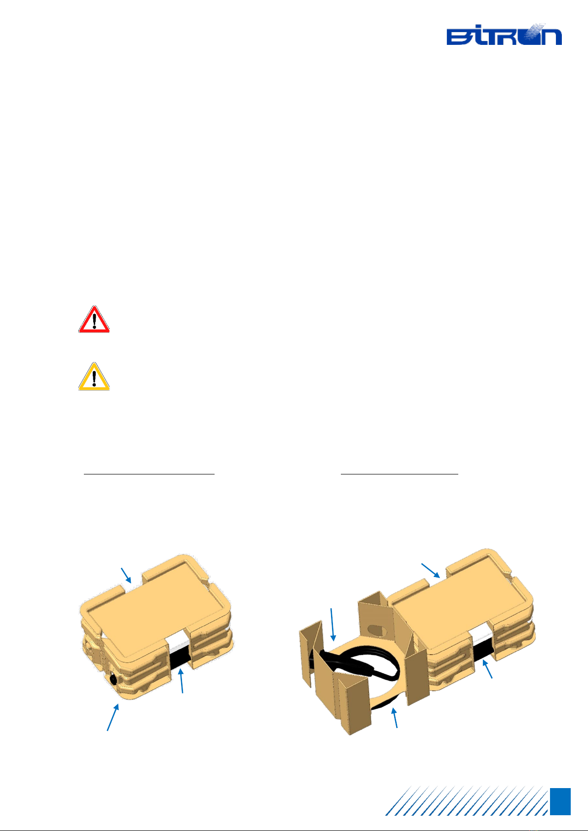
Depending on the versions, the charging stations use two types of packaging in terms of dimensions
and components arrangement. The configurations of the available packaging are as follows:
“
AC Wall SOCKET” versions
Model
s with socket
External box dimensions
: 450 x 300 x 190 mm
Total weight with product
: 4 kg
“
AC Wall PLUG” versions
Model
s with cable
External box dimensions
: 750 x 300 x 250 mm
Total weight with product
: from 5 kg to 6 kg max.
UPPER
PROTECTION
CONNECTOR
POSITION
CABLE POSITIONING
(
varies depending on the model)
CHARGING
STATION
PLUG
UPPER
PROTECTION
CHARGING
STATION
SOCKET
SIDE
PROTECTIONS

AC WALL Socket & Plug – Installation Manual
14 / 57
EN
The external cardboard box is made from a single sheet, suitably
shaped, and folded.
It is not closed using adhesive tape, and always opens on the longest
side. To open it, pull and lift the front, which will remain connected to
the box itself. This solution makes it possible to have ample space to
access to the contents, which can be taken out easily.
To blade or sharp object is required to open the box, and we
strongly recommend that you do not use them, as they can
damage the contents.
4.2 Package contents
“AC Wall SOCKET” e “AC Wall PLUG” charging stations always come with a basic installation kit. The
following elements are contained in the package:
Charging station (according to the model / version ordered)
User Card, that can be used to download the user's manual by scanning the QR-Code
Drilling template for wall mounting
3 screws M6 x 60 mm
3 wall plugs M10 x 60 mm
Some product versions for particular applications or specific Countries may include other accessories,
for which a dedicated installation and configuration guide can be provided.
4.3 Required tools
Mechanical and electrical installation of the charging unit call for tools that are normally part of an
installer's standard equipment. The unit manufacturer never provides these tools, which can easily
be obtained from your regular distributors.
Indicatively, we recommend the following equipment:
-Straight screwdrivers 0.8x4 / 0.4x3.5
-Torx head screwdrivers T20 / T15
-Electrician's wire stripper or cutters / Craft knife
-Pencil or marker pen / Tape measure / Spirit level
-Hexagonal or polygonal fixed spanner, size 26 mm
-Drill / Masonry bit, size 10 mm
-Crimper for electric wire terminals
AC WALL Socket & Plug – Installation Manual
15 / 57
EN
5PRE-REQUISITE
Before beginning actual installation, it is essential to have full knowledge of the environmental,
mechanical, and electrical pre-requisites that BITRON prescribed, in order to complete the task safely
and effectively.
Compliance with the pre-requisites below does not by-pass the duty to conform to the
norms, procedures, and any local restrictions in force at the time of installation, application
of which is the sole responsibility of the installer.
5.1 Positioning
Positioning the charging station is a very important choice that calls for abiding by some
specifications that guarantee proper functioning over time, as well as ensuring an adequate level of
safety, which is necessary for devices of this kind.
The positioning choice has to respect the current norms and prohibitions imposed by local
regulations. The installer is aware that they are solely responsible for correct positioning,
which must also take the practicality of daily use of the charging station into account.
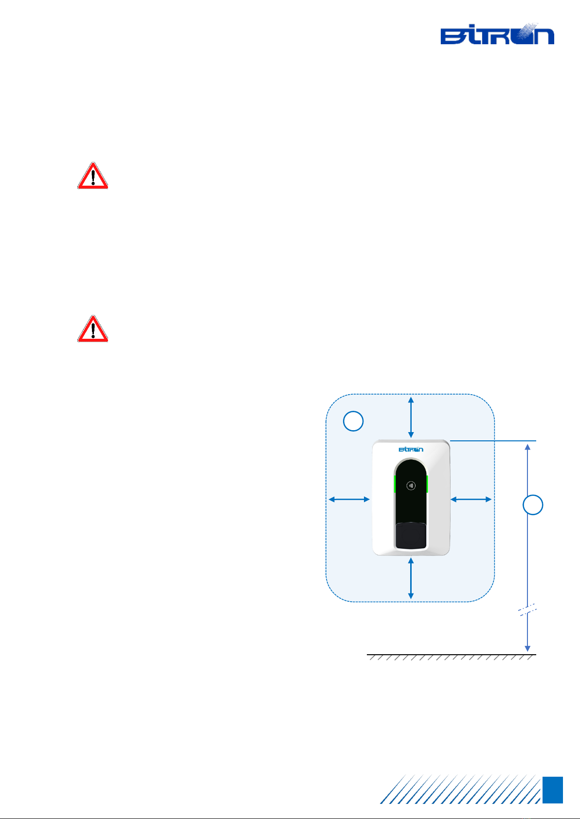
A summary of basic requirements recommended by the manufacturer is provided below:
We recommend positioning the charging
station at a height at which there are 150-
160 cm (1) between the walking surface
and the upper end of the unit. Check that
these dimensions are not contrary to the
local regulations in terms of accessibility
criteria.
Make sure that all sides of the charging
station are at least 30 cm (2) from any
object, wall, or obstacle that may reduce
air circulation or facilitate contact with
liquids or flammable materials.
The support in which the charging station
is to be installed must be flat, stable,
secured, in good condition, and strong
enough to support the weight in addition
to the force imposed during daily handling
of the cables, for connecting to the vehicle.
Never install the unit on walls that are mobile or semi-mobile, flammable, or clad in flammable
material, adjacent to passageways or emergency exit routes, with plumbing (water, oils, etc.) or
gas plants even if not flammable (compressed air).
30 cm
30 cm
30 cm
2
150 – 160 cm
30 cm
1
SUOLO

AC WALL Socket & Plug – Installation Manual
16 / 57
EN
Make sure there are no heat or electromagnetic sources in the vicinity of the charging station,
and that the place chosen is sufficiently ventilated.
Positioning must take into account the practicality and simplicity of accessing the vehicle's
connector using the cable available (provided or at the station), without making charging
operations difficult or possible dangerous.
Always leave adequate space to access to the charging station, to allow routine and extraordinary
maintenance tasks to be carried out easily.
Make sure that the ambient conditions, in terms of temperature, altitude, and humidity, are
conform to the product's specifications. Avoid environmental conditions too salty, acidic, or base.
Where possible, avoid positioning in direct sunlight and where exposed to bad weather.
In order to take advantage and activate all the functions proposed by the product, make sure the
area chosen is covered by a mobile phone service or an adequate and robust wi-fi signal.
5.2 Repositioning
The charging station can be repositioned and installed again in the future. Moving it involves
deactivation, mechanical and electrical disconnection, movement and installing it again, following the
installation procedure indicated in this manual.
Before starting, some aspect must be taken into account:
Deactivation: disconnect the incoming power cables, after ensuring that all the actions required
to avoid any risk of electrical damage to people or property have been taken. Disconnect all the
other cables in place (see managing the external disconnecting coil, Ethernet connections,
RS485, etc.).
Removal: follow the same removal procedures for the device's front parts, as described in the
procedures laid down in this manual. Unscrew the screws that fix the device to the wall, being
careful to avoid applying excessive force on the plastic parts. We recommend disposing of the 3
screws and their wall plugs.
Checking: having removed the device from the wall, we recommend visually checking that it is in
good condition. Make sure that, while operating, excessive dust residue has not been spread
around or foreign bodies have not been introduced, which may bring about malfunctions in the
future. Then close the product using the relevant screws, and according to the procedures.
Moving and storing: Handle the unit with care and put it in its original packaging. Store the
product in accordance with the indications in the technical specifications table.
Reinstalling: Proceed in strict accordance with the indications contained in this manual,
scrupulously abiding by each requirement in the exact order indicated. We recommend returning
to the default settings before beginning with configuring it again (see the "Reinstating default
configuration" su-chapter).

AC WALL Socket & Plug – Installation Manual
17 / 57
EN
5.3 General electrical requirements
All the information required for correctly sizing the electrical infrastructure that powers the charging
station, is provided below. Complying with these pre-requisites ensures a safe installation process
and correct functioning of the unit for day-to-day use.
It is essential that we once again stress that design of the electricity supply that powers the
charging station must conform to the norms, procedures, and any local restrictions in force
at the time of installation, application of which is the sole responsibility of the installer.
installation must always conform to IEC 60364-7-722 (Low-Voltage Electrical
Installations) standard and any local variations thereto.
The charging station's electrical characteristics are indicated on the product label applied on
the outside. See the "Identity Labels" sub-chapter.
“AC Wall SOCKET” and “AC Wall PLUG” charging stations are compatible with the types of electrical
networks listed below:
Single-phase Distribution
-Type TT / 230VAC with Neutral
-Type TN-S / 230VAC with Neutral
-Type TN-C-S / 230VAC with Neutral
-Type IT / 230VAC without Neutral
Three-phase Distribution
-Type TT / 400VAC with Neutral
-Type TN-S / 400VAC with Neutral
-Type TN-C-S / 400VAC with Neutral
The charging stations must always be fitted with an earthing connection. Should a fault occur on any
of the components or a malfunction arise, the earth provides the route of least resistance for the
electrical current, in order to reduce the risk of electric shocks.
Incorrect connection of the unit's earth conductor may result in the risk of electric shocks. If
there is any doubt as to the product being earthed correctly, do not continue with installation,
and make sure you proceed correctly.
Some vehicles require the charging station Neutral (N) to be in direct contact with the Earth.
In the case of Type IT networks or where they are without Neutral (N), this may give rise to
malfunctioning of the charging process. We therefore recommend installing a transformer
upstream of the differential switch (RCD) and the thermal magnetic switch (MCB) in order to
create a local Type TN electrical system.

AC WALL Socket & Plug – Installation Manual
18 / 57
EN
5.4 External protections required
“AC Wall SOCKET” and “AC Wall PLUG” charging stations require installation of external protection
systems, upstream of the unit, which must have exclusively a 6 mA DC direct current detection
device.
As a result, in conformity to the IEC 61851-1 standard, the charging station must be protected by a
thermal-magnetic switch (MCB) and a differential switch (RCD) installed externally upstream, the
minimum characteristics of which are indicated below:
MCB – Thermal-magnetic circuit breaker
-Recommended curve type: D
-Nominal short-circuit capacity: 5 kA
-Nominal current: as per charging station configuration (32A max)
-I2t value at the connector in case of a short-circuit: 75000 A2s max
-Magnetic passing energy: I2t ≤ 60000 A2 s
-Conformity to standards: IEC 60947-2, IEC 60947-6-2, IEC 61009-1 or respective
sections of IEC 60898 or IEC 60269 series
RCD – Differential circuit breaker
-Type: A o B (see local norms), manual resetting only
-Residual operating current: not exceeding nominal 30 mA
-Type of activation: disconnecting all live conductors
-Conformity to standards: IEC 61008-1 or IEC 61009-1 or IEC 60947-2 or IEC 62423
The table below provides additional technical details for the protection systems, based on the
charging station's power.
Grid
Type
Charging Station Thermal-magnetic switch Differential switch
Power Current Curve ICC In Pins Type Id In Pins
Single
Phase
Up to
3,7 kW 16 A D 10 kA 20 A 2 A 30 mA 25 A 2
Up to
7,4 kW 32 A D 10 kA 40 A 2 A 30 mA 40 A 2
Three
phase
Up to
11 kW 16 A D 10 kA 20 A 4 A 30 mA 25 A 4
Up to
22 kW 32 A D 10 kA 40 A 4 A 30 mA 40 A 4
In order to avoid any risk to the unit, the vehicle, and the electrical infrastructure, please take
note of the following indications:
1) To prevent potential damage to the electric vehicle caused by over-voltages, we strongly
recommend protecting the power supply to the connection point with an SPD (Surge
Protection Device), which can be used at all levels of the grid.
AC WALL Socket & Plug – Installation Manual
19 / 57
EN
2) We wish to point out that, for TN type electrical networks, local requirements may also
be in place on system safety and protection against faults, which the installer must
understand and implement in a workmanlike manner.
3) For IT type electrical network, an insulation monitoring device (IMD) must be installed
that permanently checks the insulation resistance. This must be of a type that conforms
to the CEI EN 61557-8 standard.
4) The device is not fitted with a PEN type fault detection system. When working with a TN
type electrical network, the circuit that powers a connection point must not be included
in a PEN conductor.
5) For “AC Wall PLUG” charging stations equipped with cable, installation of shunt release
coil may be required, that is compatible with the automatic switch chosen. For
installations, see the "Cable-fitted versions specificities" section in this manual.
5.5 Power cables
It is essential that the charging station be powered via cables of a size suitable for supporting the
current intensity for which it is designed. The electrical characteristics of the unit can be seen in this
manual and on the product label affixed externally, a description of which is available in the "Identity
labels" sub-chapter.
When designing the electricity supply, account must be taken of the type of cables, their cross-
section, the insulating materials, the maximum bending radius allowed, and, in general, it must be
sized in accordance with local norms in force at the time of installing the unit.
The specifications provided below relate to typical sizing, using copper cables. The installer must
consider the specificity of the system in each case:
Single-phase Stations
-Models up to 3,7 kW – 16A →Minimum section 4 mm2
-Models up to 7,4 kW – 32A →Minimum section 6 mm2
Three-phase Stations
-Models up to 11 kW – 16A →Minimum section 4 mm2
-Models up to 22 kW – 32A →Minimum section 6 mm2
In particular cases, for needs related to the distance to be covered or specific regulations within the
installation context, larger size cables can be used up to 10 mm2, which is the maximum size that can
be accepted by the terminal boards available.
Failure to respect the power cable specifications results in a high index of risk when installing
and using the unit. Never power the device if there is any doubt as to strict application of the
requirements indicated above.
This manual suits for next models
1
Table of contents


