ensto One Home EVH161-HC000 User manual

ENG
Ensto One Home
RAK131_ENG
15.4.2020
© Ensto 2020
Installation Guide
User Guide
EVH161-HC000
EVH321-HC000
EVH161-HCR00
EVH321-HCR00

RAK131_ENG / © Ensto 2020
2 / 28
Contents
Installation Guide............................................................. 3
1. Safety instructions................................................................................... 3
2. Delivery contents..................................................................................... 3
3. Mounting instructions............................................................................. 4
3.1. Before installation....................................................................... 4
3.2. Cable entries................................................................................ 5
3.3. Wall mounting.............................................................................. 7
4. Power supply............................................................................................ 9
5. Commissioning........................................................................................ 11
5.1. Installer menu in the Ensto Charger Control Application....... 11
6. Technical information............................................................................. 12
7. Dimension drawing................................................................................. 13
8. Installation / Commissioning checklist.................................................. 14
9. EVH161-HC000 / EVH321-HC000 internal circuit example................. 15
10. EVH161-HCR00 / EVH321-HCR00 internal circuit example.............. 16
11. Troubleshooting.................................................................................... 17
User Guide......................................................................... 18
12. Introduction........................................................................................... 18
13. Safety instructions for User................................................................. 18
14. Intended use.......................................................................................... 18
15. User interfaces....................................................................................... 19
16. Charging in “Free charging” mode....................................................... 19
17. Maintenance / Preventive maintenance instructions....................... 20
18. Residual current device testing instructions...................................... 20
19. Disposal.................................................................................................. 21
20. Warranty................................................................................................. 21
21. Declaration of Conformity.................................................................... 21
22. Ensto Charger Control Application...................................................... 22
22.1. Commissioning the application............................................... 22
22.2. Pairing the charger with your mobile device......................... 23
22.3. Application user interface......................................................... 24
22.4. Charging in “Authorized” mode................................................ 25
22.5. Error messages.......................................................................... 26

RAK131_ENG / © Ensto 2020 3 / 28
Plug
Fixed cable
Installation Guide
1. Safety instructions
Electrically skilled person
• The installation must only be done by an electrician with the appropriate qualica-
tions.
• Read this Installation and User Guide carefully before starting the installation work.
• Follow the instructions in this Installation and User Guide, and make sure that the in-
stallation complies with national safety regulations, installation methods and restric-
tions.
• The information provided in this Installation and User Guide in no way exempts the
installer or user from responsibility to follow all applicable safety regulations.
• This Installation and User Guide is a part of the product and must be stored in a safe
location so that it is available for future installation and service.
WARNING
Danger of electric shock! Risk of re!
• Improper installation can cause personal injury and property damage.
• Do not switch on the power supply before the installation work is completed.
2. Delivery contents
• EVH Charger
• Cable gland M32/M25 (depending on the model)
• Installation and User Guide in English,
other languages please see www.ensto.com.
• Multilingual Quick Guide
4-color LED indicates
the charger’s status
Plug holder
Screw xing /
mechanical hatch lock
(depending on the model)

RAK131_ENG / © Ensto 2020
4 / 28
Recommendation
900 - 1200 mm
Follow always national regulations and
site requirements
min. 200 mm min. 200 mm
3. Mounting instructions
3.1. Before installation
Remove the charger from its package. Do not scratch the surface of the charger after removal
from the package.
When selecting installation site, take into account the following:
• The charger is suitable for indoor and outdoor use.
• In order to ensure the optimal charging performance, the charger should not be exposed
to direct sunlight.
• The minimum space needed for operating and maintenance.

RAK131_ENG / © Ensto 2020 5 / 28
3.2. Cable entries
• Take the cable routing into consideration when planning the installation. The supply cable
can be routed into the enclosure from the rear or bottom. Default cable routing is from
the bottom.
• The M32 cable gland for the supply cable is pre-assembled on the bottom of the charger.
• If you need to open additional cable entries, you have to disassemble the charger.
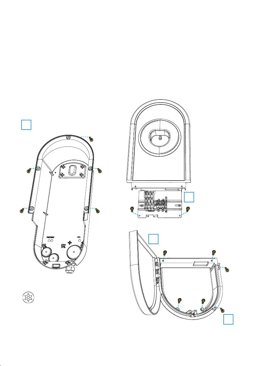
Installation steps when cable routing is from alternative cable entries
1. Disassemble the charger.
TX20
Insert
Base
Installation
box cover
1
Screw xing: Remove the screws 2pcs.
Mechanical lock: Unlock the hatch with a coin or suchlike.
2Remove the screws 4pcs.
Remove the installation box cover.
3Remove the
screws 2pcs.
4Remove the screws 5pcs.
Remove the insert from the base.

RAK131_ENG / © Ensto 2020
6 / 28
Accessories
Part number Description Note
PMR1217.32B Black cover plug for M32 opening
KTM24.25/BLACK M25 cable gland for cable Ø 10 - 16mm EVH161-HC000/EVH161-HCR00:
included 1pc
PMR1219.3225B Black reduction nipple, M32 => M25 EVH161-HC000/EVH161-HCR00:
included 1pc
RGM16B Membrane gasket for cable Ø 5 - 9mm
RMM25B Membrane gasket for cable Ø 8 - 17mm
RMM32B Membrane gasket for cable Ø 12 - 24mm
2. Open the needed cable entries with a step drill bit.
3. Prepare the cable entries with suitable accessories.
4. Remove the included cable gland from the bottom and close the cable entry with a cover
plug, PMR1217.32B (accessory).
5. Assemble the base and insert.
6. Assemble also the installation box cover, if electrical cables are installed in a separate
session.
2 x M16
1 x M25 / M32
2 x M16
1 x M25 / M32
M32 cable gland for cable Ø 17-25mm
pre-assembled

RAK131_ENG / © Ensto 2020 7 / 28
1270
367.5
108.5
max. Ø12
7
max. Ø5
Installation steps
1. Use screw type depending on the wall type.
2. Fasten the upper screw 1270 mm measured from the ground
surface. The plug holder will be at a height of 1200 mm.
3.3. Wall mounting
• When selecting the installation location, make sure that the wall material is suitable and
robust. The mounting surface should be at and vertical.

RAK131_ENG / © Ensto 2020
8 / 28
3. Open the installation box hatch by removing the fastening screws (2 pcs) / unlocking the
hatch lock [1].
4. Remove the entire installation box cover by unscrewing the fastening screws (4 pcs) [2].
5. Hang the charger on the screw you attached to the wall.
6. Secure the charger on wall with two washers and fastening screws (not included) [3].
Do not damage the charging cable!
7. Pull the electrical cables approx. 150mm through the cable glands.
8. Cut the supply cable leads in suitable lengths. Leave the ground lead long enough so that
if a fault occurs it is the last one that comes loose.
9. Strip the leads 11 mm and connect to the supply connectors.
10. Put the installation box cover back in right position and secure with the screws you re-
moved.
11. Close the installation box hatch.
1
2
3
TX20
Tightening torque 1,5 Nm

RAK131_ENG / © Ensto 2020 9 / 28
4. Power supply
The voltage and current ratings including cable sizes must comply with national regulations.
The system dimensioning must be done by a qualied electrical designer.
EVH161-HC000 / EVH321-HC000:
• Install a residual current device (RCD type A, 30mA) and a circuit breaker (MCB max. 16A
or max. 32A depending on charger model) to the supply line. In addition follow local regu-
lations for the power supply line.
L1
L2
L3
PE
CP
PP N
L1
CP
N
L1 NPE
PE
Fixed charging cable
Supply
Cu 2.5 - 10 mm²

RAK131_ENG / © Ensto 2020
10 / 28
EVH161-HCR00 / EVH321-HCR00:
• A combined device with residual current circuit breaker and over current protection
(RCBO) is integrated.
• A label set of RCBO testing instructions is included in the delivery. Attach a language spe-
cic label on the installation box hatch.
L1
L2
L3
PE
CP
PP N
L1
CP
N
L N
PE
PEPE
L N
QF1
Fixed charging cable
Supply
Cu 2.5 - 10 mm²

RAK131_ENG / © Ensto 2020 11 / 28
5. Commissioning
The charger is ready to use after the installation is completed. The charger is in “Free charging“
operating mode.
If you need to change the operating mode to “Authorized” or make other changes to the charg-
er, please download the Ensto Charger Control Application. You can download the application
from Google Play or App Store.
Please see instructions in chapter 22. Ensto Charger Control Application on pages 22 - 27.
5.1. Installer menu in the Ensto Charger Control Application
WARNING
Danger of electric shock! Risk of re!
• Settings described in this chapter must only be done by an electrically skilled person.
If the electric system dimensioning on the installation site requires a lower charging current
than the charger’s nominal value, you can change the setting with the Ensto Charger Control
application.
• Go to “Support”.
• Press the letter Eon the ENSTO logo for a long time.
• Go to “Max charging current”.
• Select the desired maximum charging current value.
• Corm your setting with “OK”.
• The new maximum charging current is now set.

RAK131_ENG / © Ensto 2020
12 / 28
6. Technical information
Electrical Connections EVH161-HC000 EVH321-HC000 EVH161-HCR00 EVH321-HCR00
Nominal supply
voltage 1-ph, 230 VAC
Nominal frequency AC 50 Hz
Charging current max. 1x16A 1x32A 1x16A 1x32A
Charging power max. 3600W 7400W 3600W 7400W
Supply connections
and terminals
L1, N, PE
Cu 2.5–10 mm² / Tightening torque: 1.5 - 1.8 Nm
Design and Mechanics EVH161-HC000 EVH321-HC000 EVH161-HCR00 EVH321-HCR00
Material Polycarbonate
Color Frame: RAL7021 dark grey
Cover: Silver
Installation box Screw xing Mechanical hatch lock
Weight 5,4 kg
Enclosure class IP54
Impact resistance
rating IK10
Operating temperature -40 °C … +50 °C
Mounting Wall Wall
User Interface EVH161-HC000 EVH321-HC000 EVH161-HCR00 EVH321-HCR00
Connection to vehicle Fixed cable
Charging status
indication
4-color LED:
Green = Ready / Blue = Charging / Red = Error / Yellow = SW update
Use access Free access / Mobile application
Safety Features EVH161-HC000 EVH321-HC000 EVH161-HCR00 EVH321-HCR00
RCD
RDC-DD
Type A 30mA must be installed in
distribution board RDC-DD
RCBO integrated
MCB
Max. 16A must
be installed in
distribution
board
Max. 32A must
be installed in
distribution
board
Control and
Communication EVH161-HC000 EVH321-HC000 EVH161-HCR00 EVH321-HCR00
Operation mode Standalone
Wireless Bluetooth (the charger can be paired with only one mobile at a time )

RAK131_ENG / © Ensto 2020 13 / 28
7. Dimension drawing
208 135
513
336
358
367
109
98
70
5.5
5.5
5
Ø12.5
336
40

RAK131_ENG / © Ensto 2020
14 / 28
8. Installation / Commissioning checklist
Introduction
Check the mechanical and electrical installation according this checklist in order to make sure
that the charger is properly installed.
Checking the Installation
Go through the visual, mechanical and electrical installation when the charger is un-
powered.
CATEGORY X ITEM
Overall look You have received the ordered material.
You do not see any scratches or damages.
Mechanical
installation The charger is xed properly on installation site.
Electrical
installation
Charger’s power supply capacity meets electrical planning (cable size,
MCB…).
Review the local electrical design plan.
The the PE-cable screw is tight.
The power supply cables (L, N and PE) are properly connected.
The insulation of power supply cables is intact (L, N and PE).
The voltage between PE and N is less than 10 V.
The PE conductor resistance is less than 3 Ω.
Test the functionality of the residual current device.
Operational
check
All the LED states / color (green, blue, red) are functioning.
• Use a car simulator.
• Create fail and charge.
• Red at bootup, green at idle and blue while charging.
Ready for
use The latest software is in use.

RAK131_ENG / © Ensto 2020 15 / 28
9. EVH161-HC000 / EVH321-HC000 internal circuit example
LED Board
A1 EVI200
x1
C1
PE
PE N
L1
CP
L1 N
J1
J4
J3
J8
J16
J6
J7
J6 J1 J16 J8
J4
J5
J7 J3
L1
L1
N
N
Supply
Cu 2.5–10 mm²
Note! All signal wires must be at a sucient
distance from the power wires or protected
with insulating shield / plastic spiral.

RAK131_ENG / © Ensto 2020
16 / 28
10. EVH161-HCR00 / EVH321-HCR00 internal circuit example
LED Board
x1
C1
PE N
L1
CP
J1
J4
J3
J8
J16
J6
J7
J4
LN
QF1
LN
LN
LN
PE
A1 EVI200
J6 J1 J16 J8
J4
J5
J7 J3
Supply
Cu 2.5–10 mm²
Note! All signal wires must be at a sucient
distance from the power wires or protected
with insulating shield / plastic spiral.

RAK131_ENG / © Ensto 2020 17 / 28
11. Troubleshooting
Charging station is o, no lights on
Issue Corrective action
Mains voltage does not exist in supply
connector L. Ensure proper power supply.
The circuit breaker QF1 is o
(EVH161-HCR00 and EVH321-HCR00). Turn the QF1 on.

RAK131_ENG / © Ensto 2020
18 / 28
Fixed cable
Plug
4-color LED indicates
the charger’s status Plug holder
Screw xing /
mechanical hatch lock
(depending on the model)
User Guide
12. Introduction
This Installation and User Guide is for the Ensto One Home Charger family. Even if the fea-
tures and appearance of the dierent charger versions varies, the installation and usage of the
product always follow the principles described in this guide.
Available features depend on the charger model.
13. Safety instructions for User
WARNING
Danger of electric shock! Risk of re!
• People who are not able to operate according to the instructions must not use this
charger.
• Do not use this charger if the charger itself or the charging cable appears to be dam-
aged.
14. Intended use
• The charger is intended for charging electric vehicles, both plug-in hybrids and full battery
electric vehicles.
• Do not connect to the charger other devices, such as power tools.

RAK131_ENG / © Ensto 2020 19 / 28
16. Charging in “Free charging” mode
Start charging
• Remove the plug from the holder. First lift up-
wards so that the plug is released from the
hook inside the holder and then pull outwards.
• Connect the plug to your vehicle’s receptacle.
15. User interfaces
The charger has two operating modes “Free charging“ and “Authorized“. The default operating
mode is “Free charging“. You can change the operating mode with the Ensto Charger Control
application.
You can download the application from Google Play or App Store. Please see instructions in
chapter 22. Ensto Charger Control Application on pages 22 - 27.
LED indicator lights show the status of the charger as described below:
Charger status LED light LED operation
The charger is free and ready to use Green Stable
While you connect the charging cable Green Flashing
twice
Your vehicle is connected, charging has not started Green Waving
Your vehicle is connected, charging starts Blue Waving
Charging is ongoing Blue Stable
Error state Red Stable
Software update is ongoing.
Do not switch o the power or use the charger during
the update.
Yellow Stable
Stop charging
• Remove the plug from your vehicle.
• Put the plug back into the holder.
1
2

RAK131_ENG / © Ensto 2020
20 / 28
17. Maintenance / Preventive maintenance instructions
Do maintenance actions once a year or as needed.
With well-done maintenance you can ensure a long lifetime of the charger and keep the war-
ranty valid.
X MAINTENANCE ACTION
Clean possible dirt and dust from the charger surface. Wipe carefully with a damp cloth.
Examine the charging plug and the charging cable for wear out or mechanical damage.
Damaged parts must be replaced by an electrically skilled person.
Examine the sealings for wear out.
Damaged parts must be replaced by an electrically skilled person.
Software update, if necessary. The software update takes up to 8 minutes.
Do not switch o the power or use the charger during the update.
Test the electric protective device.
Comply local requirements for testing interval, but test the device at least once every six
months.
18. The electric protective device testing instructions
EVH161-HC000 / EVH321-HC000:
Test the residual current device (RCD) at the supply line.
EVH161-HCR00 / EVH321-HCR00:
• The combined device with residual current circuit breaker and over current protection
(RCBO) is located in the installation box.
• Open the installation box hatch.
• Press the TEST button.
• The rocker turns to 0position.
• Turn the rocker back to Iposition.
• If a fault occurs, contact an electrician.
Other manuals for One Home EVH161-HC000
1
This manual suits for next models
3
Table of contents
Other ensto Batteries Charger manuals

ensto
ensto One User manual

ensto
ensto EVF100 User manual

ensto
ensto EVB100 User manual

ensto
ensto One Home User manual

ensto
ensto Wallbox User manual

ensto
ensto EVB203E Series User manual

ensto
ensto eFiller User manual

ensto
ensto Pro EVF200 Wiring diagram

ensto
ensto EVB200EB-B4BC User manual

ensto
ensto EVH-ACRM0 Series User manual