Bizon 14/40-B74 User manual
OPERATION and MAINTENANCE MANUAL
□MODEL: BIZON 14 / 40-B74
□MODEL: BIZON 14 / 50-B81
16GA. MEDIUM CROWN STAPLER
△,!WARNING:
BEFORE OPERATING THIS TOOL, ALL OPERATORS SHOULD STUDY MANUAL TO UNDERSTAND AND FOLLOW
THE SAFETY WARNINGS AND INSTRUCTIONS. KEEP THESE INSTRUCTIONS WITH THE TOOL FOR FUTURE
REFERENCE. IF YOU HAVE QUESTIONS, CONTACT YOUR DISTRIBUTOR.
2022/06

INTRODUCTION
The pneumatic tools is a precision-built tool, designed for high speed, high volume fastening.
These tools will deliver efficient, dependable service when used correctly, and with care. As with
any fine power tool. for best performance the manufacture’s instructions must be followed. Please
study this manual before operating the tool and understand the safety warning and cautions. The
instructions on installation, operation and maintenance should be read, carefully, and the manual
kept for reference. NOTE: Additional safety measures may be required because of your particular
application of the tool. Contact your representative or distributor with any questions concerning
the tool and its use.
INDEX
INTRODUCTION…………………………..……………………………………………….….
S A F E T Y I N S T R U CTIONS………………………………………………………………….…
AIR SYSTEMS……………………………………………………………………………….…
T O O L I N S T A L L A T I O N … … … … … … … … … … … … … … … … … … … … … … … … … … . . …
T O O L O P E R A T I O N … … … … … … … … … … … … … … … … … … … … … … … … … … … … . …
T O O L LOADING………………………………………………………………………….…
M A I N T E N A N C E … … … … … … … … … … … … … … … … … … … … … … … ………… … . … .
O P E R A T O R T R O U B L E S H O O T I N G … … … … ……………………………………………
TOOL SPECIFICATIONS
MODEL
LENGTH
WIDTH
HEIGHT
WEIGHT
LOAD CAPACITY
BIZON 14/40-B74
343 mm
86 mm
252 mm
2,0 kg
162 staples type 14
BIZON 14/50-B81
349 mm
94 mm
285 mm
2,19 kg
162 staples type 14
FASTENER SPECIFICATIONS
STAPLE MODEL
CROWN SIZE
WIDTH×THICKNESS
LENGTH
Stapler model
BeA / BIZON type 14
10.5 mm
1.45×1.3 mm
14-40 mm
14/40-B74
BeA / BIZON type 16
10.8 mm
1.57×1.3 mm
21-40 mm
14/40-B74
BeA / BIZON type 14
10.5 mm
1.45×1.3 mm
25-50 mm
14/50-B81
BeA / BIZON type 16
10.8 mm
1.57×1.3 mm
25-50 mm
14/50-B81
TOOL AIR FITTING
This tool uses a 1/4˝N.P.T male plug. The inside diameter should be 6,5 mm or larger.
The fitting must be capable of discharging tool air pressure when disconnected from the
air supply.
OPERATING PRESSURE
6 to 8 bar (80 to 120psi ; 5.5 to 8.3kg/cm²) Select the operating pressure within this range for best
fastener performance
DO NOT EXCEED THIS RECOMMENDED OPERATING PRESSURE.

SAFETY INSTRUCTIONS
SAFETY FIRST
These safety instructions provide information necessary for safe operation of pneumatic
tools. DO NOT attempt to operate the tool until you read and understand all safety
precautions and manual instructions.
◆WEAR EYE AND HEARING PROTECTION
Always wear hearing and eye protection devices, including side shields when
operating or working in the vicinity of a tool.
◆THE TOOL MUST BE USED ONLY FOR THE PURPOSE FOR WHICH IT WAS
DESIGNED
Do not throw the tool on the floor; strike the housing in any way or the tool as a
hammer to knock material into place.
◆NEVER ENGAGE IN HORSEPLAY WITH THE TOOL
The tool is not a toy so do not use it like one. Never engage in horseplay with the
tool or point it at yourself or any person, even if you think it is not loaded.
◆NEVER ASSUME THE TOOL IS EMPTY
Check the magazine for fasteners that may be left in the tool. Even if you think the
tool is empty or disconnected never point it at anyone or yourself. Unseen fasteners
could fire the tool.
◆NEVER CLAMP THE TRIGGER IN A LOCKED OR OPERATING POSITION.
The trigger of the tool must never be tampered with; disabled or clamped in a
locked or operating position since this will cause the tool to driver a fastener any
time the work contacting element is depressed.
◆DO NOT LOAD FASETNERS WITH THE AIR LINE CONNECTED, OR WITH THE
TOOL TRIGGER OR WORK CONTACTING ELEMENT DEPRESSED
When loading fasteners into the tool sure you disconnect the air line and that you
do not depress the trigger or work contacting element.
◆OPERATE THE TOOL ONLY ON A WORKPIECE
The tool should be operated only when it is in contact with the work piece. Even
then you should be careful when fastening thin material or working near the edges
and corners of the work piece since the fasteners may drive through or away from
the work piece.
◆DO NOT DISABLE OR REMOVE THE WORK CONTACTING ELEMENT

This tool is equipped with a safety mechanism, called a work contacting element, to
help prevent accidental firing. Never tamper with, disable or remove the work
contacting element. Do not use the tool unless the work contacting element is
working properly. The tool could fire unexpectedly.
◆DISCONNECT THE TOOL WHEN NOT IN USE
Always disconnect the tool from the air line when it is not used or when you leave
the work area. The tool should never be left unattended because people who are
not familiar with the tool might handle it and injure themselves or others.
◆CARRY THE TOOL ONLY BY THE HANDLE
Always carry the tool by the handle only. Never carry the tool by the air hose or with
the trigger depressed since you could drive a fastener unintentionally and injure
yourself or someone else. SAFETY INSTRUCTIONS
◆DO NOT WEAKEN THE TOOL HOUSING
The tool housing is a pressure vessel and should never be weakened by having your
company’s name, area of work or anything else stamped or engraved into its
surface.
◆DISCONNECT THE TOOL WHEN PERFORMING REPAIRS AND CLEARING JAMS
Never attempt to clear a jam or repair a tool unless you have disconnected the tool
from the air line and removed all remaining fasteners from the tool.
◆ALWAYS USE THE PROPER FITTING FOR THE TOOL
Only MALE pneumatic type air connectors should be fitted to the tool, so that high
pressure air in the tool is vented to atmosphere as soon as the air line is
disconnected
NEVER install FEMALE quick disconnect couplings on the tool. Female couplings
will trap high pressure air in the tool when the air line is disconnected, leaving the
tool charged and able to drive at least one fastener.
◆DO NOT EXCEED THE MAXIMUM RECOMMENDED AIR PRESSURE
Operate the tool only at the recommended air pressure. Do not exceed the
maximum air pressure marked on the tool. Be sure the air pressure gauge is
operating properly and check it at least twice a day .
Never use any bottled air or gases such as oxygen to operate the tool since they
could cause the tool to explode.
◆KEEP THE TOOL CLEAN AND LUBRICATED
Clean the tool at least daily and lubricate as required. Never operate a dirty or

malfunctioning tool.
◆USE ONLY RECOMMENDED PARTS AND FASTENERS.
Use only parts and fasteners specifically designed and recommended for use in the
tool and for the work to be done. Using unauthorized parts and fasteners or
modifying the tool in any way creates dangerous situations. Replace all missing
parts-refer to tool schematic for correct placement and part number.
DANGER
Failure to follow any of the above instructions could result
in severe personal injury to tool user and bystanders or
cause damage to tool and property.
AIR SYSTEMS
For air-powered tools to work their best, the air supply system must be properly
installed and maintained regularly. A drawing in this section shows a properly installed
air supply system Handy checklists for installing and maintaining air supply systems
follow.
◆INDOOR AIR SYSTEM INSTALLATION BE CERTAIN THAT:
All pipes supplying air have a large enough inside diameter to ensure adequate air
supply.
The main supply pipe slopes down, away from the compressor
(1/16 inch per foot).
Air storage is provided along lengthy air lines.
Pipe line branch outlets are at the top of the main pipe line.
Cut-off valves are provided at each branch pipe line throughout the system.
Water legs extend from the bottom of each branch line.
A refrigerant-type dryer is installed on the system.
Air hoses are kept as short as practical.
A regular maintenance program is followed.
◆QUTDOOR AIR SYSTEM INSTALLATION BE CERTAIN THAT:

A moisture trap and a filter/regulator/lubricator are installed at the compressor.
Air hoses and fittings are large enough so that air flow not restricted .Minimum
hose size is 3/8 inch ID, with 1/2 inch ID hose used for any application over 25
feet.
Air hoses are not longer than 150 feet.
The air system is lubricated regularly.
A regular maintenance program is followed.
◆FILTER / REGULATOR / LUBRICATOR UNITS
Filter / regulator / lubricator units that can supply enough air and protection for
pneumatic tools must meet the following specifications:
Minimum 3/8 inch NPT port size.
50 micron or finer filters.
Regulated pressure from zero to 120 psi
Lubricators designed for low or changing airflow.
TOOL INSTALLATION
DANGER
Air pressure at the tool must never exceed 8 bar
Your pneumatic tool Comes ready for immediate use and can be installed by following
these steps:
•SAFETY-All tool operators and their immediate supervisors must become familiar with
the operator safety instructions before operating the tool. The instructions are on
page 2 of this manual
•Included with each tool are one copy of this Safety and Maintenance manual and one
copy of the Tool Schematic. Keep these publications for future reference.
•The Plastic cap in the air inlet of the tool must be removed before the male air fitting
is installed The fitting must be a male pneumatic type that discharges the air from the
tool when the air line is disconnected.
•Install a filter/regulator/lubricator unit with a gauge as close as practical to the tool,

preferably within ten feet. Refer to the Air Systems section of this manual for air hose
requirements and lengths. In general, no other special installation is required.
•If the operator is working at a bench or table, it is usually best to run the air line
underneath the bench. A small tray under the benchtop can hold the fastener
supply and the tool when not in use.
•If this tool does not work when is it is first connected, do not try to make repairs. Call
your local service center immediately
DANGER
Air pressure at the tool must never exceed 8 bar
TOOL OPERATION
Depth of Drive Adjustment
WARNING
Keep the tool pointed in a safe direction.
Disconnect the tool from the air supply and remove all fasteners.
The depth of drive adjustment is made by adjusting the work contacting element. The
screw is loosened to allow the element to be moved up or down. You will need a 4 mm
hex socket wrench to make this adjustment.
Take off hex. Bar wrench set in the magazine cover.
If the tool is overdriving (the fastener head is driven below the work surface), the work
contacting element should be moved downward. if the fasteners stand up (the head or
crown is not flush with the work surface), the work contacting element should be moved
up.
Adjust the work contacting arm until the fastener head or crown depth meets job
requirements.

TOOL OPERATION
◆PRECISION PLACEMENT DRIVING:
Grasp the tool handle firmly and hold the bottom of the work contacting element
firmly against the workpiece until it is completely depressed.
Squeeze the trigger to drive the fastener.
Lift the tool from the workpiece.
Repeat the procedure for the next fastener.
◆SUCCESSIVE(BOUNCE) DRIVING
Grasp the handle firmly.
Squeeze the trigger and move the tool along the workpiece with a bouncing
motion, depressing the work contacting element at the points where you want to
insert a fastener.
Keep the trigger depressed and continue to bounce the work contacting element
against the workpiece, positioning the tool as above as carefully as possible.
When the desired number of fasteners have been driven, release the tool trigger
to avoid unintentional fastener discharge.
WARNING
Do not clamp or hold trigger with anything
Other than your hand.
◆SEQUENTIAL OPERATION
The sequential operating prevents successive or “bounce” driving.

Depress the work contacting element and hold it against the work surface before
pulling the trigger.
After each fastener is driven, completely release the trigger and lift the tool from
the work surface.
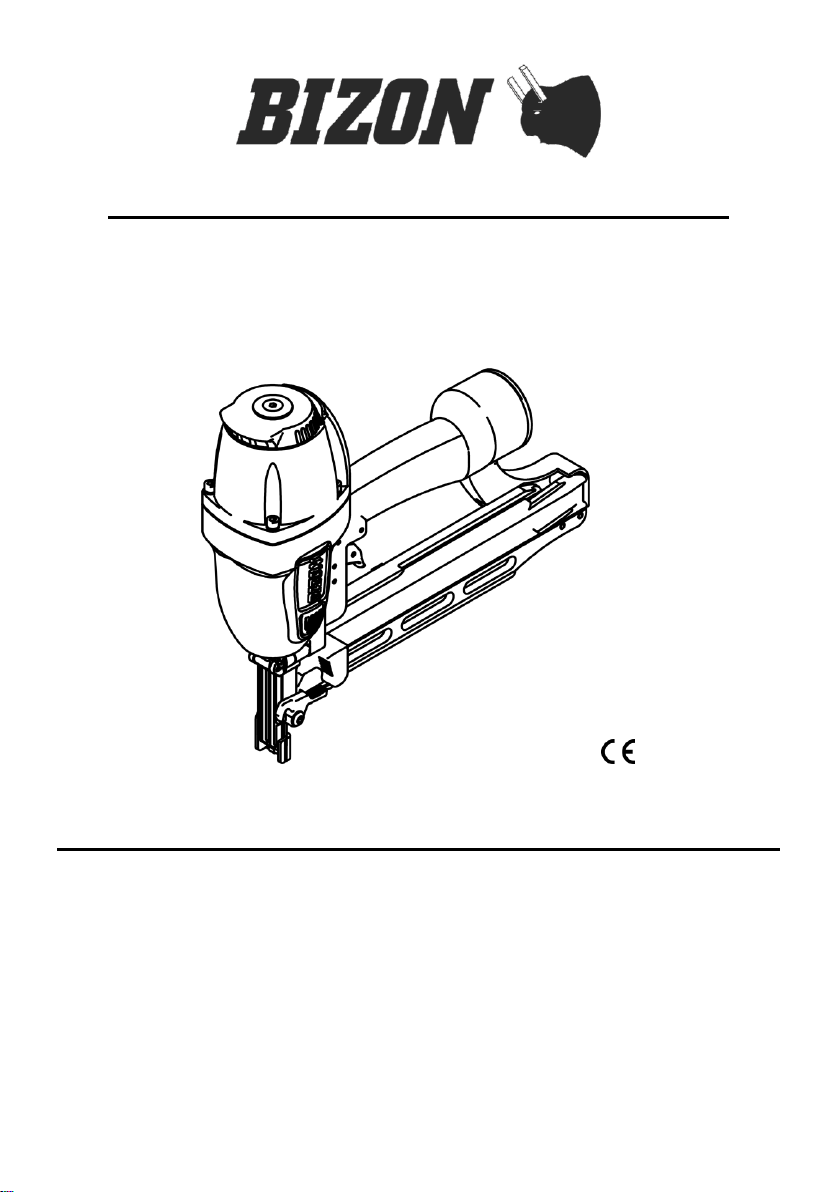
TOOL LOADING
STAPLER
(1) Grasp the stapler handle
firmly. Pull the pusher all
the way to the rear of the
magazine until it is latched
into its loading position by
the magazine slot.
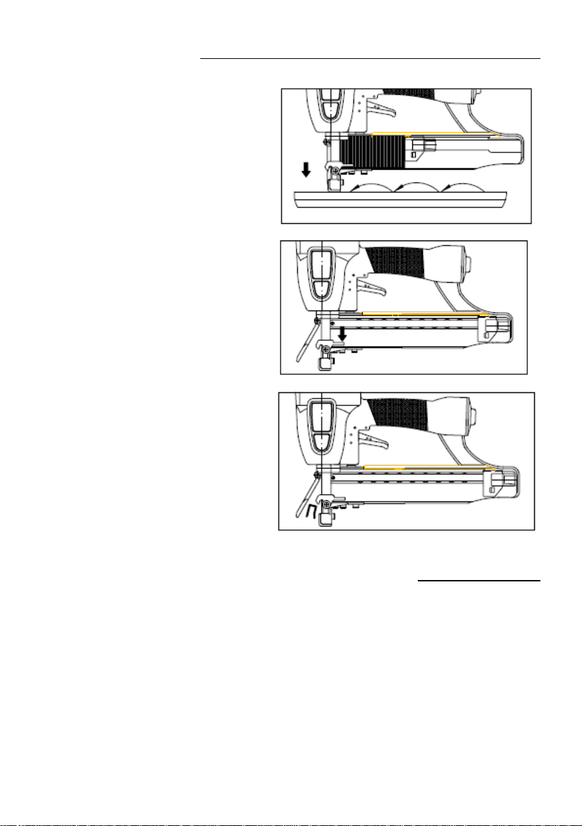
(2) Insert one or two strip of
fasteners into the top of
the magazine.
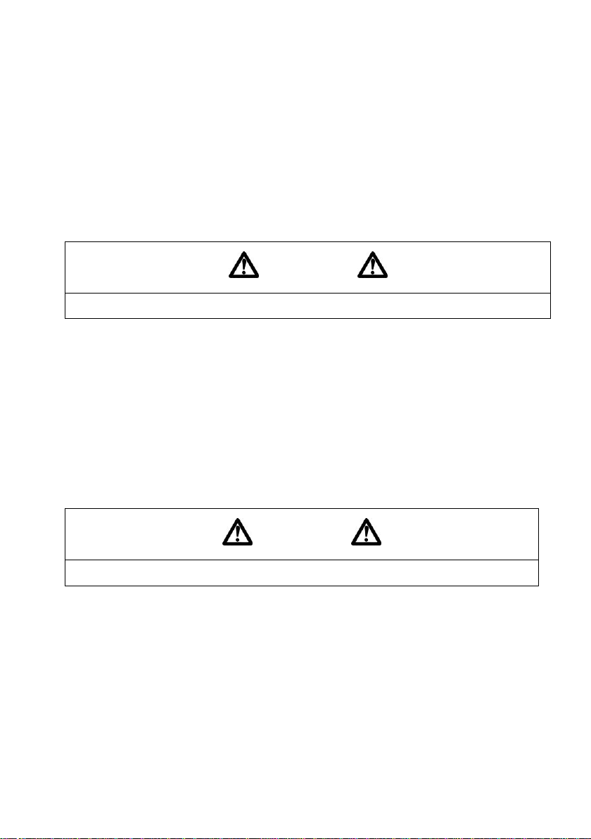
(3) Hold the pusher firmly and
slide the pusher forward
until it contacts the staples.
The tool is now ready for
use.
DRIVING FASTERS / CLEANING JAMMED STAPLE
CONTACT FIRE OPERATION
(1) Hold the trigger.
(2) Depress the contact arm against
the work surface.
CLEANING JAMMED STAPLES
(1) Take out the staples from the
inside of the magazine.
(2) Press the stopper and open door.
(3) Remove staples that are jammed
inside the nose by using a punch
or slotted screw driver.
(1) After removing the staples.
(2) Close the door and now ready for
use.
MAINTENANCE
These tools are built for ease of maintenance. A few simple details will assure
trouble-free operation and long tool life. Anyone who uses or maintains the tool must
read the safety and maintenance instructions. Study the schematic drawing before
starting any repairs on the tool.
Air-operated tools must be inspected periodically, and worn or broken parts must be
replaced to keep the tool operating safety and efficiently. Also the item on the
maintenance chart must be checked often.
◆COLD WEATHER CARE
When temperatures are below freezing, tools should be kept warm by any
convenient, safe method. If this is not possible, the following procedure should be
used to warm up the tool parts.
Reduce the regulated air pressure to 30 psi.
Remove all fasteners from the tool.
Collect an air line and blank fire the tool. The reduced air
pressure will be enough to free-fire the tool. Slow speed operation tends to warm
up the moving parts. Slowing up the piston helps bumper and the O-rings to
become springy.
CAUTION
Never free-fire the tool at high pressure.
Once the tool is warmed up, readjust the regulator to the proper working pressure
and reload the tool.
Tool operators working outdoors or in unheated areas in extremely cold
temperatures should also:
Use recommended air tool oil with antifreeze in the lubricator.
Once a week, depending on the amount of tool use ,take the tool apart and wash
away any sludge with degreaser cleaner parts to keep the tool operating
efficiently.
CAUTION
Never use kerosene or flammable solvents to clean the tool.
Cleaning air-operated tools with solvents remover the thin coating of grease applied
to the cylinder wall and ”O” rings at the factory. To replace this coating of grease,
use LITHIUM grease or equivalent on parts.
Open the drain on the air compressor tank to drain any moisture at least daily in
extremely cold or humid weather. A few ounces of anti-freeze in the tank will keep
the air free of frost.
◆TESTING THE TOOL AFTER SERVICING
After replacing any part or parts, it is important to check the tool for proper
operation. This ensures that the tool was put together correctly, is safe to use, and

will perform the job properly.
Ensure that all hardware is tight.
Ensure that the work contacting element is installed correctly in relation to the
trigger, and that both parts move freely.
Ensure that the magazine is properly attached.
Ensure that the required safety information on the tool is legible.
Use only approved fasteners in the tool, and ensure that they are correct for the
application.
Ensure that a male air fitting is securely connected to the tool.
Test the tool by driving fasteners into a workpiece identical to the tool’s
application.
Check the tool for air leaks during testing and for the proper sequence of
operation.
Ensure that all fasteners are driven to the same depth and that the crown of the
fastener is flush with the workpiece.
◆TOOL LUBRICATION
It is most important that the tool be properly lubricated by keeping the air line
lubricator filled and correctly adjusted. Without proper lubrication the tool will not
work properly and parts will wear prematurely.
Use the proper lubricant in the air line lubricator. The lubricator should be of the low
air flow or changing air flow type, and should be kept filled to the correct level. Use
only recommended lubricants. Substitutes may harm the rubber compounds in the
tool “O” rings and other rubber parts.
If a filter / regulator / lubricator is not installed on the air system, air-operated tools
should be lubricated at least once a day with 6 to 20 drops of oil, depending on the
work environment, directly through the male air fitting in the tool housing.
Most minor problems can be resolved quickly and easily using the maintenance
table that follows. If problems persist, contact your local dealer for assistance.
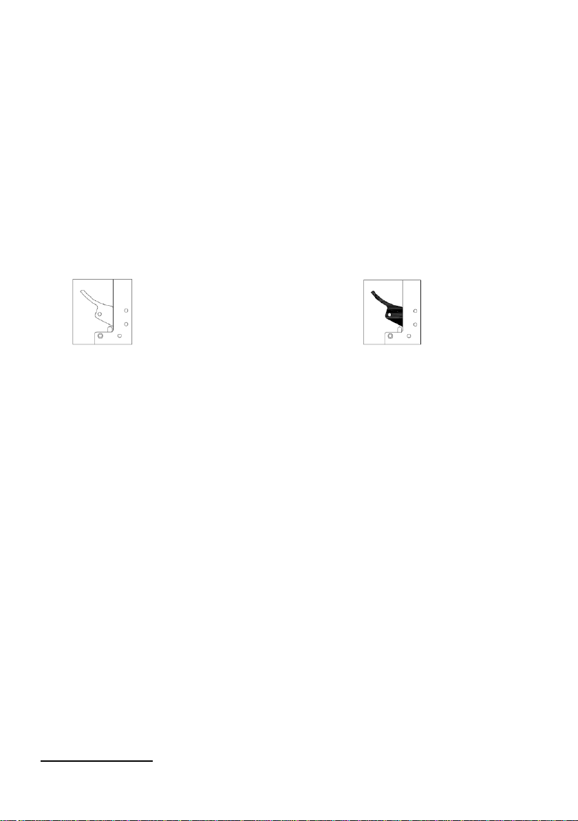
◆MODEL IDENTIFICATION
Refer to Operation instructions on page 9 before proceeding to use
for tool 14/50-B81
CONTACT TRIP - ldentified by:
BLACK TRIGGER
SEQUENTIAL TRIP - ldentified by:
ORANGE TRIGGER

MAINTENANCE
CAUTION
Disconnect the tool when performing repairs or clearing jams.
MAINTENANCE TABLE
ACTION
WHY
HOW
Drain air line filter (daily)
Prevent accumulation of
moisture and dirt.
Open manual petcock
(most air supply systems
have such a valve)
Keep lubricator filled.
Keep tool lubricated.
Fill with recommended air
tool lubricant
Clean filter element-then
blow air through filter in
direction opposite to
normal flow.
Prevent clogging of filter
with dirt.
Wash with soap and water
or follow manufacture’s
instructions..
Check that all screws on tool
are tight.
Prevent air leakage and
promote efficient tool
operation.
Check screw daily.
Keep work contacting
element working properly.
Promote operator safety
and efficient tool operation.
Blow clean daily.
Keep magazine and feeder
mechanism clean.
Prevent jamming of
fasteners.
Blow clean daily.
Lubricate ”O” rings that are
replaced.
Assure long life and proper
operation of tool.
Use lithium grease or
equivalent.
Use only recommended
replacement parts.
Keep tool operating
efficiently.
Order any replacement
parts needed from local
service center dealer.
OPERATOR TROUBLESHOOTING
CAUTION
Disconnect the tool when performing repairs or clearing jams.
PROBLEM
CORRECTIVE ACTION
Fasteners will not drive completely into wood
Adjust work contacting element (retract length).
increase air pressure(do not exceed 120 psi)
Fasteners penetrate properly during normal
operation, but won’t drive fully at faster speeds.
Increase air flow to tool-use larger air lines (3/8
inch ID minimum)
Fasteners drive too deeply into wood
Adjust work contacting element (extend length).
Reduce air pressure.
Fastener jams in nose of tool.
Open front guide latch, release jammed fastener,
and close latch securely)
Tool skips during operation-no fasteners are
driven from time-to-time.
Check magazine for proper fasteners. Magazine
follower should slide freely. Clean as needed to
remove debris.
Make sure correct fasteners are being used. Use
fasteners that meet specifications only.
Increase air flow to tool-use larger air lines(3/8
ID minimum)
Adjust work contacting element where available.
Tool operates, but no fasteners are driven.
Check magazine for proper fasteners. Fasteners
should slide freely with no follower pressure.
Open front guide latch or loosen magazine knob
and check for jams or debris in nose area. Clear
as necessary.
Increase air pressure (do not exceed 120 psi)
Air leaks at cap when tool is connected to air
Tighten cap screws.


WYKRYWANIE I USUWANIE USTEREK
UWAGA
Podczas przeprowadzania naprawy lub usuwania zaciętych zszywek należy odłączyć urządzenie od
źródeł zasilania.
PROBLEM
WŁAŚCIWE POSTĘPOWANIE
Zszywki nie są wbijane w całości
w drewno.
Należy dopasować element bezpiecznika kontaktowego (skrócić).
Należy zwiększyć ciśnienie powietrza (nie przekraczać 8 bar)
Zszywki są prawidłowo wbijane
przy normalnej pracy urządzenia,
ale nie wchodzą w pełni w
przedmiot przy większych
prędkościach.
Należy zwiększyć przepływ powietrza przez narzędzie - należy użyć
większych przewodów powietrza (minimum 8 mm )
Zszywki zbyt głęboko wchodzą
w drewno.
Należy dopasować element bezpiecznika kontaktowego (wydłużyć).
Należy zredukować ciśnienie powietrza.
Zszywki zacinają się w końcówce
narzędzia.
Należy otworzyć przednią prowadnicę zatrzasku, usunąć zaciętą
zszywkę, a następnie bezpiecznie zamknąć zatrzask.
Narzędzie podskakuje podczas
pracy - od czasu do czasu nie wbija
zszywek.
Należy sprawdzić prawidłowe ułożenie zszywek w magazynku.
Popychacz magazynka powinien przesuwać się swobodnie. W razie
potrzeby należy go oczyścić w celu usunięcia odłamków.
Należy upewnić się, że stosowane są właściwe zszywki. Należy
stosować wyłącznie te zszywki, które spełniają wymogi.
Należy zwiększyć przepływ powietrza przez narzędzie – należy użyć
większych przewodów powietrza (minimum 8 mm).
Należy dostosować bezpiecznika kontaktowego tam, gdzie jest to
możliwe.
Narzędzie pracuje, ale nie wbija
zszywek.
Należy sprawdzić prawidłowe ułożenie zszywek w magazynku.
Powinny się one swobodnie przesuwać bez nacisku popychacza.
Należy otworzyć przednią prowadnicę zatrzasku lub poluzować
pokrętło magazynka i sprawdzić, czy w końcówce nie zacięły się
żadne zszywki lub ich odłamki. W razie potrzeby oczyścić.
Należy zwiększyć ciśnienie powietrza (nie przekraczać 8 bar)
Powietrze wydostaje się przez
pokrywę cylindra, kiedy narzędzie
jest podłączone do powietrza
Należy dokręcić śruby pokrywy, sprawdzić uszczelkę.

KONSERWACJA
UWAGA
Podczas przeprowadzania naprawy lub usuwania zaciętych zszywek należy odłączyć
urządzenie od zasilania sprężonym powietrzem.
TABELA KONSERWACJI
CZYNNOŚĆ
POWÓD
SPOSÓB WYKONANIA
Czyszczenie filtra przewodu
powietrza (codziennie).
Zapobiega akumulacji wilgoci i
brudu.
Należy otworzyć ręczny kurek
(większość układów zasilania
powietrzem jest wyposażonych
w taki zawór).
Uzupełnianie NAOLEJACZA w
bloku przygotowania powietrza.
Utrzymuje urządzenie
odpowiednio nasmarowane.
Należy uzupełniać smarem
zalecanym dla narzędzi
napędzanych sprężonym
powietrzem.
Czyszczenie elementów
filtra-następnie przepuszczenie
powietrza przez filtr w kierunku
przeciwnym do kierunku
normalnego przepływu.
Zapobiega zatykaniu filtra przez
brud.
Należy umyć mydłem i wodą lub
postępować zgodnie z
instrukcjami podanymi przez
producenta.
Sprawdzenie, czy wszystkie
śruby w urządzeniu są
dokręcone.
Zapobiega wydostawaniu się
powietrza i wspiera wydajną
pracę urządzenia.
Należy codziennie sprawdzać
śruby.
Utrzymywanie prawidłowej
pracy elementu bezpiecznika
kontaktowego.
Podnosi bezpieczeństwo
operatora i wydajność pracy
urządzenia.
Należy codziennie
przedmuchiwać powietrzem.
Utrzymywanie magazynka
i mechanizmu podajnika w
czystości.
Zapobiega zacinaniu się
zszywek.
Należy codziennie
przedmuchiwać powietrzem.
Nasmarowanie wymienionych
pierścieni uszczelniających typu
o-ring. Kontrola stanu
powierzchni amortyzatora w
którą uderza tłok.
Gwarantuje długą żywotność i
właściwą pracę urządzenia.
Należy stosować smar litowy lub
podobny.
Pęknięty amortyzator należy
natychmiast wymienić.
Stosowanie wyłącznie
zalecanych części zamiennych.
Utrzymuje wysoką wydajność
pracy urządzenia.
Należy zamówić wszelkie
niezbędne części zamienne
w lokalnym centrum
serwisowym.
KONSERWACJA
◆SMAROWANIE URZĄDZENIA
Istotne jest właściwe smarowanie urządzenia poprzez stałe uzupełnianie i odpowiednią
regulację naolejacza powietrza. W przypadku braku właściwego smarowania, narzędzie będzie
pracować nieprawidłowo, a jego części ulegną przedwczesnemu zużyciu.
W smarownicy (naolejaczu) powietrza należy stosować właściwy olej dla narzędzi
pneumatycznych. Powinien się on być stale uzupełniany do odpowiedniego poziomu. Należy
stosować wyłącznie zalecane smary. Substytuty mogą uszkodzić gumowe elementy w
pierścieniach uszczelniających typu o-ring oraz inne części urządzenia.
Jeżeli blok przygotowania powietrza (filtr / regulator / naolejacz) nie jest zainstalowany w
systemie powietrza, narzędzia napędzane sprężonym powietrzem należy smarować kilka razy
dziennie stosując od 3 do 10 kropli oleju, w zależności od środowiska pracy, bezpośrednio
poprzez męskie przyłącze powietrza w obudowie urządzenia.
Większość niewielkich problemów można szybko i łatwo rozwiązać posiłkując się poniższą
tabelą konserwacji. W przypadku utrzymywania się danego problemu, w celu uzyskania
dodatkowej pomocy należy skontaktować się ze swoim lokalnym sprzedawcą.
◆IDENTYFIKACJA MODELU- tryb wyzwalania
Przed kontynuacją pracy z urządzeniem należy powrócić do rozdziału Użytkowanie
Urządzenia na stronie 8.
TRYB KONTAKTOWY (CON)
Znak rozpoznawczy:
CZARNY SPUST
TRYB SEKWENCYJNY (SEQ)
Znak rozpoznawczy:
POMARAŃCZOWY SPUST
Spust do pojedynczego wyzwalania (SEQ) „pomarańczowy” dostarczany jest w
opakowaniu z modelem 14/50-B81 do innych modeli zszywaczy konstrukcyjnych BIZON
dostępny na życznie.
This manual suits for next models
1
Table of contents


