manuals.online logo
Brands
  1. Home
  2. •
  3. Brands
  4. •
  5. Aimco
  6. •
  7. Power Tools
  8. •
  9. Aimco URW Series Operating instructions

Aimco URW Series Operating instructions

PO Box 16460, Portland, OR 97292-0460 503-254-6600 Fax 503-255-2615
URW Series
URW-6, 8, 9, 10 & 12 Series
Repair Manual
Contents
Page
Number
1. Tools Needed for Repair 1
2. Disassembly and Reassembly of the Cam Casing 2-4
3. Disassembly and Reassembly of the Gear Section 5-9
4. Disassembly and Reassembly of the Air Motor Section 10-14
5. Recommended Maintenance 15
October 2006 -1-
Tools Needed for Repair
1. One Set of T-Handle Metric Allen Wrenches
2. Flat-Bladed Screwdrivers
3. Brass Hammer
4. Dead Blow Hammer
5. 10 oz. Ball Peen Hammer
6. One Set of Pin Punches
7. One Set of O-Ring Picks
8. 6” Adjustable End Wrench
9. 12” Adjustable End Wrench
10. Medium Pair Channel Locks or Adjustable Jaw Pliers
11. Medium Honing Stone
12. 220 Grit Wet/Dry Sandpaper
13. Lap Plate
14. Loc-Tite #242
15. CFC Free Degreaser-Cleanser
16. Loc-Tite Accelerator
17. Arbor Press
18. UTA-204 and UMS Transducers and UFT Joint Simulators
19. Needle Nose Pliers
20. Propane Torch
October 2006 -2-
Disassembly and Reassembly of the Cam Casing
Disassembly
1. Remove the Rod Guide Bolts and Rod Guide Nuts.
2. Remove the Rod Guides, Ratchet, Checker, Springs, and Rod Plate Spring.
3. Remove the Cam Casing from the tool (left-hand thread).
•On the URW-6, you must loosen the Gear Casing Lock Nut first and then remove the Connector, Cam,
Bearing, Spacer, Thrust Washers, and Thrust Bearing.
•On the URW-8N & 9N, over-tightening the Handle Nut will keep the Casing from turning.
4. Remove the Operating Rod, Cam Roller, Cam Roller Pin, Cam Roller Push Pin(s), and Spring(s).
5. Thoroughly clean all parts.
Inspection of Parts for Wear
1. Rod Guides:The Ratchet should turn freely in the Rod Guides but should not move from side to side;
replace as needed.
2. Ratchet and Checker:The teeth should come to a point; replace if they are rounded off. The flats inside
of the Ratchet should not be pitted or grooved; replace as needed.
3. Operating Rod:The end of the Rod that contacts the Ratchet should come to a point; replace if it’s
rounded.
4. Cam Roller and Cam Roller Pin:The Cam Roller should be round and smooth; replace if it has flat spots
and pitting. The Cam Roller Pin should be inspected for shininess and grooving; replace as needed.
5. Rod Plate Spring:Inspect the Rod Plate Spring for cracks and wear from the Operating Rod; replace as
needed.
6. Springs:Check for the correct dimension of the Spring; replace as needed.
Reassembly
1. Install the Cam Roller Push Pin(s) and Spring(s) into the Cam Casing. Put a light coat of grease on both
parts.
2. Install the Cam Roller and the Cam Roller Pin into the Operating Rod. Now install the Operating Rod into
the Cam Casing making sure that the Cam Roller Push Pin gets under the Cam Roller Pin. Put a light coat
of grease on all parts.
3. Put a light coat of grease on the Operating Rod and install the Rod Plate Spring.
4. Install the Springs and Checker onto the Cam Casing.
5. Install the Ratchet and Rod Guides being sure to line up the slot in the Rod Guide with the notch on the
Checker. Install the Rod Guide Bolts and Nuts and tighten.
6. When installing the Cam Casing Assembly back onto the Gear Casing, the Cam Casing Assembly will have
to be shimmed to adjust the Operating Rod to the Ratchet.
October 2006 -3-
Disassembly and Reassembly of the Cam Casing (cont.)
Adjusting the Cam Casing Assembly
For all Tools Except the URW-6:
1. While running the tool, reinstall the Cam Casing to the Gear Casing.
2. Watch the Ratchet as the Cam Casing turns down onto the Gear Casing. When the Ratchet starts to turn,
mark its position and continue to allow the Cam Casing to turn down onto the Gear Casing until the Ratchet
stops or the Cam Casing bottoms out.
3. Turn the Cam Casing back halfway between the two points and measure the amount of Adjusting Spacers it
will take to take up the space between the Cam Casing and the Gear Casing.
For the URW-6 Only:
1. Install the Connector into the Gear Casing. Now install the Thrust Washers, Thrust Bearing, Spacer,
Bearing, and Cam into the Connector.
2. While running the tool, reinstall the Cam Casing onto the Connector.
3. Watch the Ratchet as the Cam Casing turns down onto the Connector. When the Ratchet starts to turn, mark
its position and continue to allow the Cam Casing to turn onto the Connector until the Ratchet stops or the
Cam Casing bottoms out.
4. Turn the Cam Casing back halfway between the two points and measure the distance from the bottom of the
Cam Casing to the top of the Gear Casing.
5. Turn the Cam Casing down until it bottoms out and measure the distance from the bottom of the Cam
Casing to the top of the Gear Casing. Subtract the two measurements; this is the amount of Adjusting
Spacers that should be put between the Cam Casing and the Connector.
October 2006 -4-
Disassembly and Reassembly of the Cam Casing (cont.)
URW - Cam Casing
Part
Number
Description
Part
Number
Description
1
2
3
4
5
6
7
8
9
10
Checker
Ratchet
Snap Ring
Spring
Rod Guide Left
Round Head Screw
Rod Plate Spring
Spring Washer
Cam Roller Pin
Operating Rod
11
12
13
14
15
16
17
18
19
Cam Roller
Spacer (URW-8N only)
Rod Guide Nut
Spring
Cam Roller Push Pin
Cam Casing
Grease Cup
Rod Guide Right
Rod Guide Bolt
October 2006 -5-
Disassembly and Reassembly of the Gear Casing
Disassembly
1. Remove the Cam Casing (left-hand thread).
2. On the URW-6 Only:
a. Remove the Connector from the Cam Casing. Remove the Cam, Bearing, Spacer, Thrust Washers, and
Thrust Bearing.
b. Remove the Gear Casing, Gear Cage, Roller Pins, Planet Gears, Needle Roller Bearings, and Bearing.
c. Remove the Allen Head Dog Point Screw from the side of the Gear Casing. Remove the Internal Gear
and Bearing.
3. On the URW-8N & 9N:
a. Using a Bearing Separator, put it between the Cam and the Casing to remove the Cam, Key, Bearing,
Thrust Rear Spacer or Spacer, and Thrust Bearing from the Casing.
b. Remove the Casing from the Handle.
c. Remove the Air Motor from the Casing.
d. Remove the Bearing, Gear Cage, Needle Rollers, Planet Gear Bushings (on URW-8N only), and
Internal Gear from the Casing.
4. On the URW-8:
a. Using a Bearing Separator, put it between the Cam and the Casing to remove the Cam, Key, Bearing,
Thrust Rear Washer, and Thrust Bearing from the Casing.
b. Remove the Gear Casing from the Handle.
c. Remove the Gear Cage, Roller Pins, Planet Gear Bushings, and Planet Gears from the Gear Casing.
d. Remove the Internal Gear from the Gear Casing.
5. On the URW-10N, 12N, 12NA & 12NB:
a. Remove the Cam, Bearing, and Spacer from the Gear Casing.
b. Remove the Gear Casing from the Casing. Note:Over-tightening the Handle Nut will help keep the
casing from turning.
c. Remove the Gear Cage, Planet Gear Pins, Needle Roller Bearing, Bearing, and Planet Gears from the
Gear Casing.
6. Thoroughly clean all parts and blow dry.
Inspection of Parts for Wear
1. Cam:Inspect for pitting and flat spots; replace as needed.
2. Needle Rollers and Planet Gear Pins:Inspect for shininess and grooving; replace as needed.
3. Planet Gears and Internal Gears:Inspect teeth for pitting and grooving; replace as needed.
4. Bearings:Inspect for side play and knocking; replace as needed.
October 2006 -6-
Disassembly and Reassembly of the Gear Casing (cont.)
Reassembly
1. Grease all Bearings, Gears, and Internal Gears.
2. For the URW-6 Only:
a. Install the Bearing, Internal Gear, and Allen Head Dog Point Screw into the Gear Casing.
b. Install the Needle Roller Bearing into the Planet Gears and both Planet Gears into the Gear Cage. Put
the Roller Pins into the Gear Cage and through the Planet Gears.
c. Install the Spacer onto the Gear Cage and install the Gear Cage into the Gear Casing. Install the
Bearing into the Gear Cage.
d. Install the Gear Casing onto the Air Motor Casing.
e. Install the Connector onto the Gear Casing and install the Thrust Washers, Thrust Bearing, Spacer,
Bearing, and Cam into the Connector.
3. For the URW-8N & 9N:
a. Install the Internal Gear into the Casing.
b. Install the Planet Gear Bushing (URW-8N only) into the Planet Gear and install them into the Gear
Cage. Install the Needle Rollers into the Gear Cage.
c. Install the Gear Cage into the Casing and install the Key into the Gear Cage.
d. Install the Bearing, Thrust Rear Spacer or Spacer, and Thrust Bearing onto the Cam. Press the Cam
onto the Gear Cage making sure to line up the Key in the Gear Cage with the key way in the Cam.
Note:The Gear Cage should extend out past the Cam about 2mm.
4. For the URW-8:
a. Install the Internal Gear into the Gear Casing.
b. Install the Planet Gear Bushing into the Planet Gears and install the Planet Gears into the Gear Cage.
Install the Needle Rollers into the Gear Cage.
c. Install the Gear Cage into the Gear Casing and install the Key into the Gear Cage.
d. Install the Bearing, Thrust Rear Spacer or Spacer, and Thrust Bearing onto the Cam. Press the Cam
onto the Gear Cage making sure to line up the Key in the Gear Cage with the key way in the Cam.
Note:The Gear Cage should extend out past the Cam about 2mm.
5. For the URW-10N, 12N, 12NA, & 12NB:
a. Install the Needle Roller Bearing into the Planet Gears and both Planet Gears into the Gear Cage. Put
the Planet Gear Pins into the Gear Cage and through the Planet Gears.
b. Install the Spacer onto the Gear Cage and install the Gear Cage into the Gear Casing. Install the
Bearing onto the Gear Cage.
c. Install the Bearing and Cam onto the Gear Cage.
October 2006 -7-
Disassembly and Reassembly of the Gear Casing (cont.)
URW-6 - Gear Casing
Part
Number
Description
Part
Number
Description
1
2
3
4
5
6
7
8
9
10
Cam
Bearing
Thrust Washer
Connector
Cam Casing Lock Nut
Grease Cup
Set Screw
Spacer
Roller Pin
Needle Roller Pin
11
12
13
14
15
16
17
18
19
20
Planet Gear
Spacer
Thrust Bearing
Adjusting Spacer
Gear Casing
Bearing
Internal Gear
Gear Cage
Bearing
Spacer
October 2006 -8-
Disassembly and Reassembly of the Gear Casing (cont.)
URW - Gear Casing
Part
Number
Description
Part
Number
Description
1
2
3
4
5
6
7
Cam
Bearing
Spacer
Thrust Bearing
Set Screw
Gear Casing
Internal Gear
8
9
10
11
12
13
Key
Planet Gear
Roller Pin
Bushing
Gear Cage
Bearing
October 2006 -9-
Disassembly and Reassembly of the Air Motor
Disassembly
1. For the URW-6:
a. Remove the Gear Casing from the Handle Casing.
b. Remove the Air Motor from the Handle Casing. Note:Applying heat to the Handle may help in
removing the Air Motor.
c. Tap on the splined end of the Rotor with a brass hammer while holding the Air Motor firmly in your
hand. Remove the Front Plate, Bearing, and Cylinder.
d. Press the Rotor out of the Rear Plate and Bearing.
2. For the URW-8N & 9N:
a. Remove the Casing from the Handle Casing.
b. Remove the Air Motor from the Casing.
c. Tap on the splined end of the Rotor with a brass hammer while holding the Air Motor firmly in your
hand. Remove the Front Plate, Bearing, and Cylinder.
d. Remove the Snap Ring, Rear Plate Spacer, and O-ring from the Rear Plate. Press the Rotor out of the
Rear Plate and the Bearing out of the Rear Plate.
3. For the URW-8:
a. Remove the Gear Casing from the Handle Casing.
b. Remove the Air Motor from the Handle Casing. Note:Applying heat to the Handle Casing may help in
removing the Air Motor.
c. Tap on the splined end of the Rotor with a brass hammer while holding the Air Motor firmly in your
hand. Remove the Front Plate, Bearing, and Cylinder.
d. Remove the Snap Ring, Rear Plate Spacer, and O-Ring from the Rear Plate. Press the Rotor out of the
Rear Plate and the Bearing out of the Rear Plate.
4. For the URW-10N, 12N, 12NA & 12NB:
a. Remove the Casing from the Handle Casing.
b. Remove the Air Motor from the Casing.
c. Tap on the splined end of the Rotor with a brass hammer while holding the Air Motor firmly in your
hand. Remove the Front Plate, Bearing, and Cylinder.
d. Press the Rotor out of the Rear Plate and Bearing.
5. Thoroughly clean all parts and blow dry.
Inspection of Parts for Wear
1. Air Motor Blades:Inspect Blades for splitting and side wear; replace if worn.
2. Bearings:Inspect Bearings for side play and knocking; replace if worn.
3. Cylinder:Inspect Cylinder for waviness; replace if worn.
October 2006 -10 -
Disassembly and Reassembly of the Air Motor (cont.)
4. Air Motor Plates:Inspect Plates for grooving. Light marks can be lapped out using a figure-eight motion
with 220 grit sandpaper on a Lap Plate. If heavy grooving is noted, replace.
5. Rotor: Inspect Rotor for sharp edges in Blade Slots and pitting and grooving on Plate Surface. Light marks
can be stoned with a medium oil stone. If deep markings exist, replace.
6. O-Ring:Inspect the O-rings for splitting or chipping; replace if necessary.
Reassembly
1. For the URW-6:
a. Remove the Casing from the Handle Casing.
b. Grease all Bearings. Place the Rear Plate on the rear of the Rotor and press the Rear Bearing onto the
Rotor. Note:There should be a slight amount of drag between the Rear Plate and the Rotor.
c. Lightly coat the Blades with air motor oil and install them in the Rotor flat-side out.
d. Place the Cylinder down over the Rotor making sure to line up the air port holes in the Rear Plate with
the holes in the Cylinder.
e. Install the Front Plate onto the Rotor and press the Front Bearing over the Rotor and into the Front Plate.
Note:The Cylinder should be tight between the Front and Rear Plate and the Rotor should turn freely.
f. Install the alignment Pin through the Rear Plate, Cylinder, and into the Front Plate.
g. Install the Air Motor into the Handle lining up the hole in the Handle with the alignment Pin in the Air
Motor.
2. For the URW-8N & 9N:
a. Grease all Bearings. Place the Rear Plate on the rear of the Rotor and press the Rear Bearing onto the
Rotor. Note:There should be a slight amount of drag between the Rear Plate and the Rotor.
b. Lightly coat the Blades with air motor oil and install them in the Rotor flat-side out.
c. Place the Cylinder down over the Rotor making sure to line up the air port holes and Roll Pin in the
Cylinder with the holes in the Rear Plate.
d. Install the Front Plate onto the Rotor aligning the Roll Pin in the Cylinder and press the Front Bearing
over the Rotor and into the Front Plate. Note:The Cylinder should be tight between the Front and Rear
Plate and the Rotor should turn freely.
e. Install the O-ring, Rear Plate Spacer, and Snap Ring into the Rear Plate.
f. Install the Air Motor into the Casing and install the Handle.
3. For the URW-8:
a. Grease all Bearings. Place the Rear Plate on the rear of the Rotor and press the Rear Bearing onto the
Rotor. Note:There should be a slight amount of drag between the Rear Plate and the Rotor.
b. Lightly coat the Blades with air motor oil and install them in the Rotor flat-side out.
c. Place the Cylinder down over the Rotor making sure to line up the air port holes and Roll Pin in the
Cylinder with the holes in the Rear Plate.
October 2006 -11 -
Disassembly and Reassembly of the Air Motor (cont.)
d. Install the Front Plate onto the Rotor aligning the Roll Pin in the Cylinder and press the Front Bearing
over the Rotor and into the Front Plate. Note:The Cylinder should be tight between the Front and Rear
Plate and the Rotor should turn freely
e. Install the O-ring, Rear Plate Spacer, and Snap Ring into the Rear Plate.
f. Install the Air Motor into the Handle lining up the hole in the Handle with the alignment Pin in the Air
Motor.
4. For the URW-10N, 12N, 12NA & 12NB:
a. Grease all Bearings. Place the Rear Plate on the rear of the Rotor and press the Rear Bearing onto the
Rotor. Note:There should be a slight amount of drag between the Rear Plate and the Rotor.
b. Lightly coat the Blades with air motor oil and install them in the Rotor so that the bevel of the Blade
goes with the bevel of the Rotor.
c. Place the Cylinder down over the Rotor making sure to line up the air port holes and Roll Pin in the
Cylinder with the holes in the Rear Plate.
d. Install the Front Plate onto the Rotor aligning the Roll Pin in the Cylinder and press the Front Bearing
over the Rotor and into the Front Plate. Note:The Cylinder should be tight between the Front and Rear
Plate and the Rotor should turn freely.
e. Install the Air Motor into the Casing and install the Handle.
October 2006 -12 -
Disassembly and Reassembly of the Air Motor (cont.)
URW - Air Motor
Part
Number
Description
Part
Number
Description
1
2
3
4
5
6
Bearing
Front Plate
Cylinder
Roll Pin
Rear Plate
Bearing
7
8
9
10
11
Rear Plate Spacer (URW-8 & 9)
Blade
Rotor
O-Ring (URW-8 & 9)
Snap Ring (URW-8 & 9)
October 2006 -13 -
Recommended Maintenance
The tools should be thoroughly cleaned and inspected every three months. Always use genuine Uryu parts.
Lubrication
Use a light spindle oil for the air motor like Mobile Spindle Oil No. 1, Shell Spindle Oil 60, and/or equivalent.
Use a high-quality grease for the Gearing, Cam, and Racheting sections like Shell Alvania No. 2, Mobilplex 2,
and/or equivalent.
Corporate Headquarters AIMCO Corporation de Mexico SA DE CV
10000 SE Pine Street Ave. Cristobal Colon 14529
Portland, OR 97216 Chihuahua, Chihuahua. 31125
800-852-1368 Mexico
FAX 800-582-9015 Phone: (01-614) 380-1010
www.aimco-global.com Fax: (01-614) 380-1019
LIT-MAN480
Rev. 07/2020
Printed in USA
©2020 AIMCO

This manual suits for next models

5

Other Aimco Power Tools manuals

Aimco PISTOL User manual

Aimco

Aimco PISTOL User manual

Aimco AcraDyne Gen III 2000 Series User manual

Aimco

Aimco AcraDyne Gen III 2000 Series User manual

Aimco AcraDyne AcraDrive 2000 Series User manual

Aimco

Aimco AcraDyne AcraDrive 2000 Series User manual

Aimco AcraDyne Gen 4 HT Series User manual

Aimco

Aimco AcraDyne Gen 4 HT Series User manual

Aimco AcraDyne ABETP Cordless XT Series User manual

Aimco

Aimco AcraDyne ABETP Cordless XT Series User manual

Aimco Auditor User manual

Aimco

Aimco Auditor User manual

Aimco UOW Series Operating instructions

Aimco

Aimco UOW Series Operating instructions

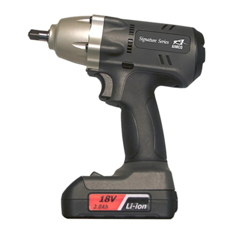
Aimco Signature Series User manual

Aimco

Aimco Signature Series User manual

Aimco AcraDyne Gen III 3000 Series User manual

Aimco

Aimco AcraDyne Gen III 3000 Series User manual

Aimco AcraDyne Gen IV 2000 Series User manual

Aimco

Aimco AcraDyne Gen IV 2000 Series User manual

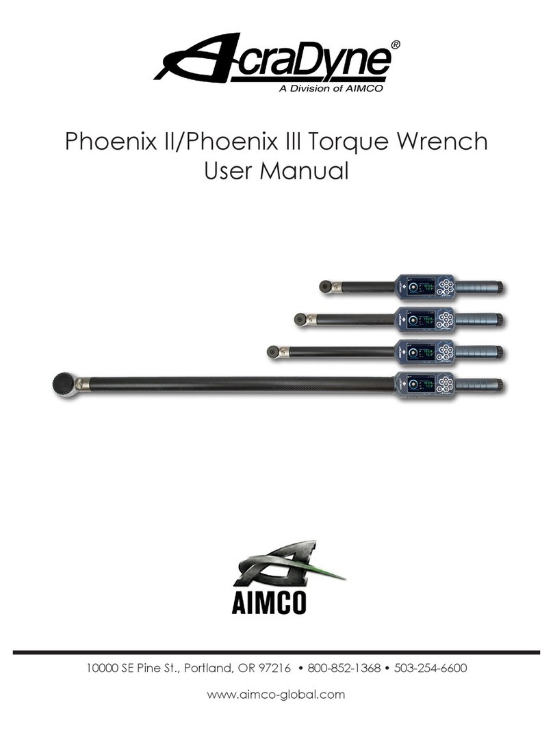
Aimco AcraDyne Phoenix II User manual

Aimco

Aimco AcraDyne Phoenix II User manual

Aimco AcraDyne Gen IV 2000 Series User manual

Aimco

Aimco AcraDyne Gen IV 2000 Series User manual

Aimco AcraDyne Gen III 3000 Series User manual

Aimco

Aimco AcraDyne Gen III 3000 Series User manual

Aimco AcraDyne HT Series User manual

Aimco

Aimco AcraDyne HT Series User manual

Aimco AcraDyne HT ABG Series Operation manual

Aimco

Aimco AcraDyne HT ABG Series Operation manual

Aimco AcraDyne HT Series User manual

Aimco

Aimco AcraDyne HT Series User manual

Aimco UAT Series Operating instructions

Aimco

Aimco UAT Series Operating instructions

Aimco UBX-T Series User manual

Aimco

Aimco UBX-T Series User manual

Aimco Signature Series User manual

Aimco

Aimco Signature Series User manual

Aimco SIW-P3225Q User manual

Aimco

Aimco SIW-P3225Q User manual

Aimco AcraDyne AB-CTA User manual

Aimco

Aimco AcraDyne AB-CTA User manual

Aimco AcraDyne Gen III 2000 Series User manual

Aimco

Aimco AcraDyne Gen III 2000 Series User manual

Aimco AcraDyne 1000 Series User manual

Aimco

Aimco AcraDyne 1000 Series User manual

Popular Power Tools manuals by other brands

Makita DTWA100 instruction manual

Makita

Makita DTWA100 instruction manual

EASTMAN BBS32 Instruction book and parts list

EASTMAN

EASTMAN BBS32 Instruction book and parts list

U-Line H-491 quick start guide

U-Line

U-Line H-491 quick start guide

Erbauer ERB389JSW manual

Erbauer

Erbauer ERB389JSW manual

Makita M1901B Repair manual

Makita

Makita M1901B Repair manual

MQ Multiquip Mikasa MVC-80VH Operations & parts manual

MQ Multiquip

MQ Multiquip Mikasa MVC-80VH Operations & parts manual

Gardebruk Deuba MZUK001 instructions

Gardebruk

Gardebruk Deuba MZUK001 instructions

Makita DTW284 instruction manual

Makita

Makita DTW284 instruction manual

National Flooring Equipent 5700 Service manual

National Flooring Equipent

National Flooring Equipent 5700 Service manual

DeWalt DWE314 Original instructions

DeWalt

DeWalt DWE314 Original instructions

Makita JS1000 instruction manual

Makita

Makita JS1000 instruction manual

Clarke STRONG-ARM CSA12F Operation & maintenance instructions

Clarke

Clarke STRONG-ARM CSA12F Operation & maintenance instructions

Stihl ASA 85 instruction manual

Stihl

Stihl ASA 85 instruction manual

Hilti SIW 9-A22 Original operating instructions

Hilti

Hilti SIW 9-A22 Original operating instructions

CAMPAGNOLA STARK M quick guide

CAMPAGNOLA

CAMPAGNOLA STARK M quick guide

Gage Bilt GB2581 Original instructions

Gage Bilt

Gage Bilt GB2581 Original instructions

Perel VL102P user manual

Perel

Perel VL102P user manual

Greencut GM560L-4 instruction manual

Greencut

Greencut GM560L-4 instruction manual

manuals.online logo
manuals.online logoBrands
  • About & Mission
  • Contact us
  • Privacy Policy
  • Terms and Conditions

Copyright 2025 Manuals.Online. All Rights Reserved.