BJB Enterprises Centerpointe CPE-325 User manual
by BJB Enterprises, Inc.
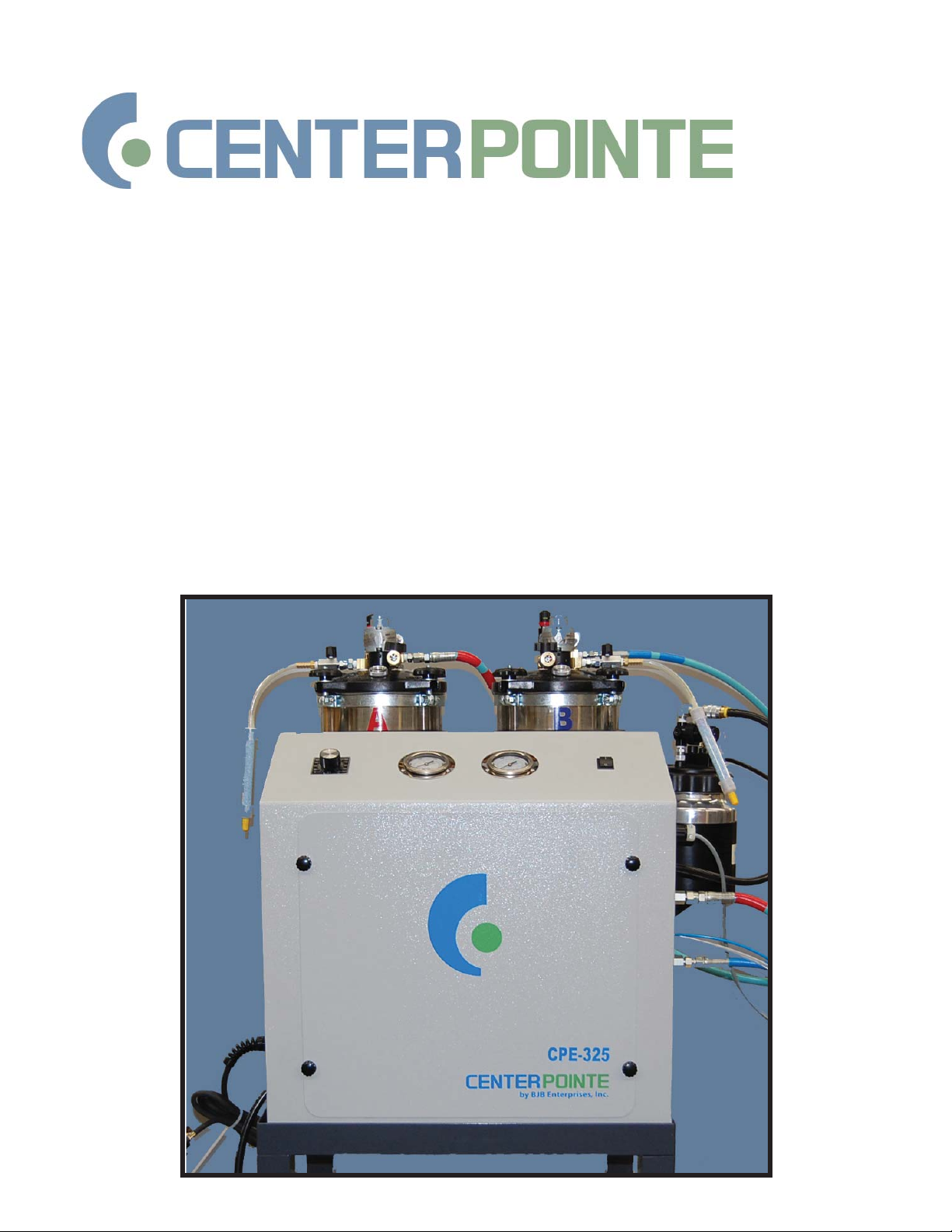
CPE-325
Meter-Mix Dispense System
Operations Manual

2 CPE-325 Operation Manual
www.centerpointe-equipment.com
Centerpointe
by BJB Enterprises, Inc.
14791 Franklin Avenue
Tustin, California 92780
PH: 714-734-8450
Fx: 714-734-8929
www.centerpointe-equipment.com

CPE-325 Operation Manual 3
714.734.8450
CPE-325
Table of Contents
Section: Page
1) System Requirements............................................................................... 4
2) Initial Start-up.............................................................................................. 4
3) Loading Material......................................................................................... 6
4) Heater Controls........................................................................................... 8
5) De-Airing Material...................................................................................... 8
6) Setting Speed and Ratio.......................................................................... 10
7) Dispensing Material.................................................................................. 12
8) Solvent Flush System (Optional)........................................................... 12
9) Daily Shut Down........................................................................................ 14
10) Weekly Maintenance.............................................................................. 16
11) Long Term Storage.................................................................................. 17
Trouble Shooting............................................................................................ 18
Warranty............................................................................................................. 20

4 CPE-325 Operation Manual
www.centerpointe-equipment.com
CENTERPOINTE EQUIPMENT
CPE-325
Meter-Mix Dispense System
Operating Instructions
1) SYSTEM REQUIREMENTS
• Air Supply - approximately 80 (psi) @ 15 CFM.
• 120 Volt single phase 20-amp power supply.
• For optional Solvent Flush System - Solvent for ush cleaning the gun head and static
mix tubes. (Recommended solvent – SC-105 available at BJB)
2) INITIAL START-UP
• Your unit was shipped with ushing uid in the hoses and pumps. This must be removed
and not allowed to mix with resin. Remove tank lids and make sure tanks are free of any
uid. Wipe dry with a clean rag.
• Fill solvent tank with recommended solvent. (BJB SC-105)
• Connect Air supply. (see g. 2.1)
• Connect Power supply.
• Put a drop of air tool oil in air inlet on lid mixers. (see g. 2.2)

CPE-325 Operation Manual 5
714.734.8450
Fig. 2.1
Fig. 2.2

6 CPE-325 Operation Manual
www.centerpointe-equipment.com
3) LOADING MATERIAL
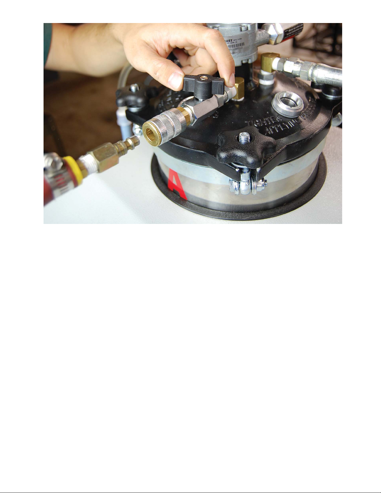
• Place the ball valves under the tanks in the closed position. (see g. 3.1)
• Remove the lids.
• Pour the selected resin system into the feed tank. Do not ll tank while other tank is
un-covered. Material may splash from one tank into the other, causing particles to form
which will eventually be drawn into the pump. Make sure that the ‘A’ and ‘B’ components
are poured into the appropriate tanks.
• Leave enough space for material to rise during vacuum process (1/2 to 2/3 full).
• A minimum of one gallon should be poured into each tank to prevent the heaters from
scorching the material.
• Replace the lids and begin stirring the material. The lid mixers should turn slowly so as not
to introduce more air into the material. (see g. 3.2)
• Set the control knob on the heater bands to a low setting and increase gradually to
desired temperature. (see g. 3.3)
• Follow procedures in Section 5 for degassing material.
• Open the desiccant tube valves located on the lids. During machine operation, air must
be allowed to enter the tanks as the liquids are drawn out to prevent a vacuum lock. The
air going into the tanks should enter via the desiccant tubes. (see g. 3.4)
• Remove lids and place over waste containers (see g. 3.5). To purge any remaining solvent
or previous material from the lines, open ball-valves under tanks and start pumps (see
section 6 to run pumps). Run until a steady, clean stream of material ows from re-
circulation tubes on tank lids.

CPE-325 Operation Manual 7
714.734.8450
Fig. 3.1 Fig. 3.2
Fig. 3.3 Fig. 3.4
Fig. 3.5

8 CPE-325 Operation Manual
www.centerpointe-equipment.com
4) HEATER CONTROLS
• The ‘A’ and ‘B’ tank heaters are adjusted by the temperature control knobs on the heater
bands, and can be accessed through the front panel. Do not adjust heater controls while
pumps are running and chain is in motion.
• Check material temperatures frequently to prevent over heating. 80°-90° F is normal for
material temperatures.
• Mixers should be turning slowly to prevent uneven heating.
5) DE-AIRING MATERIAL
• Make sure the ball valves under the tanks are in the closed position.
• Turn o lid mixers.
• Attach the vacuum line to vacuum port on the lid. (see g. 5.1)
• Close desiccant tube valve on lids.
• Open the ball valve on the vacuum port, and proceed to pull a vacuum. Monitor level
of material constantly through the viewport while under vacuum. Using a ashlight,
shine light through one viewport while observing material in the other viewport. If the
material level approaches the top of the tank, you must close the vacuum port valve to
avoid the material being drawn into the vacuum hose. With the yellow cap removed
from the desiccant tube (see g. 3.3), open the air valve to allow bubbles to settle. Repeat
process until material settles on its own. Some materials with high viscosities may require
opening the air valve on the tank two to three times before the material level drops on its
own. BJB’s anti-foam products may help dissipate the bubbles in the tanks more easily.
• When vacuuming is complete, close the vacuum port valve, remove the vacuum line and
open the desiccant tube valve.
CPE-325 Operation Manual 9
714.734.8450
Fig. 5.1

10 CPE-325 Operation Manual
www.centerpointe-equipment.com
6) SETTING SPEED AND RATIO
Setting the Speed
• Adjusting the speed on the CPE-325 is accomplished by adjustments made to the speed
control knob located on the front panel of the unit. (see g. 6.1)
• When the knob is turned clockwise the pump speed will increase. When the knob is
turned counter-clockwise the pump speed will decrease.
Setting the Ratio
• Adjusting the ratio is accomplished by changing the sprocket size on the pumps. Addi-
tional sprockets can be purchased from BJB.
• Loosen locking bolt on chain idler to relieve chain tension and change pump sprocket as
necessary. Re-adjust chain for proper tension (chain should have approximately 1/2” up
and down play). (see g. 6.2)
Checking the Ratio
• It is recommended to insure the ratio is within tolerance (check with your material manu-
facturer).
• Attach supplied ratio head by removing the mix tube nut and aligning the smaller slot on
the ratio head with the n on the gun head manifold (see g 6.3). Tighten the ratio head
nut snuggly.
• Straddle the ratio head over the rims of two cups. (see g 6.4)
• Dispense enough material to provide an accurate weight measurement (typically 100
grams of combined material).
• Weigh each cup; divide the smaller weight by the larger weight to acquire the ratio. For
example, if you have 43 grams ‘A’ and 78 grams of ‘B’, your ratio would be 43/78 or 55/100
by weight. If you have 92 grams ‘A’ and 56 grams ‘B’ then you ratio would be 92/56 or
100/60.
• If the ratio is not within tolerance refer to “Setting the Ratio”.

CPE-325 Operation Manual 11
714.734.8450
Fig. 6.1 Fig. 6.2
Fig. 6.3 Fig. 6.4

12 CPE-325 Operation Manual
www.centerpointe-equipment.com
7) DISPENSING MATERIAL
• At start-up, always dispense at a low speed. Cold viscous material can cause high
pressures. High pressures can cause relief valve to discharge or gun seals to fail.
• Open the ball valves under the tanks, and open the desiccant tube valves on the lids.
• If the ratio head was used to determine the proper machine setting, remove it and replace
it with a mix tube.
• Dierent material systems generally have their own unique handling characteristics. Run
some test shots before lling a mold. Check for correct pot life, nal cured hardness, and
the complete mix of components.
• When nished dispensing material, point the gun in a downward position, remove the
static mix tube, and wipe the end of the gun-head manifold clean. This will prevent any
material reaction in the manifold orices.
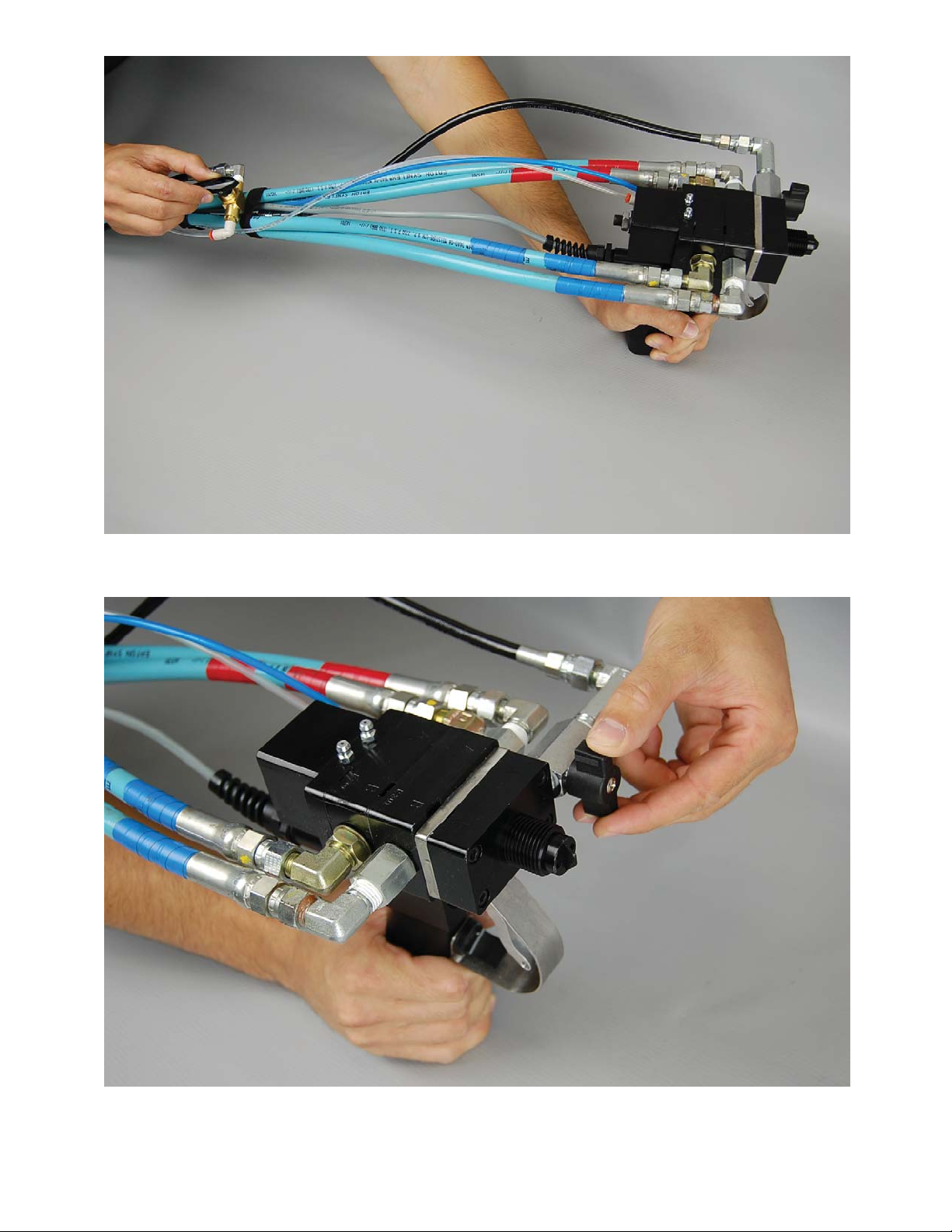
8) SOLVENT FLUSH SYSTEM (OPTIONAL)
• When dispensing is complete, ush mix tube immediately.
• The valves for air and solvent are located behind the gun head assembly (g. 8.1), turning
the valve to the right, towards the clear hose, will allow air to ow through the gun head
manifold; to the left, towards the black hose, will allow solvent to ow.
• Open the ball valve on the gun head manifold (g 8.2) to allow solvent or air to ow
through the A side port and through the mix tube. Alternate ushing with solvent and air
and repeat until the gun head manifold and mix tube are thoroughly clean.
• When nished with the solvent ush close the ball valve on the gun head manifold so
that material will not back ow into the solvent tank.
CPE-325 Operation Manual 13
714.734.8450
Fig. 8.1
Fig. 8.2

14 CPE-325 Operation Manual
www.centerpointe-equipment.com
9) DAILY SHUT DOWN
• Close the ball valves under feed tanks.
• Cap o desiccant tubes and close the valves.
• Disconnect the air supply and power supply.
• Purge tanks with dry nitrogen or evacuate air by vacuum. Replace lids and secure hold
downs.
• Do not relieve pressure on system, this will cause air to enter material lines, and harden
material in hose.
• Remove nozzle end from gun and ush both ‘A’ and ‘B’ orices with solvent. Wipe gun face
clean. Replace nozzle and install night cap. (see g. 9.1)
• Apply small amount of APG#2 grease to gun valve grease ttings. (see g. 9.2)
• Put a drop of air tool oil in each air mixer inlet.

CPE-325 Operation Manual 15
714.734.8450
Fig. 9.1
Fig. 9.2

16 CPE-325 Operation Manual
www.centerpointe-equipment.com
10) WEEKLY MAINTENANCE
• Check tanks for any hardening of material and re-apply dry nitrogen and tighten lids.
• Check chain and sprockets for tension, lube chain with small amount of lithium grease.
• Open bleed valve screw located on bottom center of pump, (it may be necessary to hold
main body of bleed valve to prevent entire valve from turning). Apply APG#2 grease to
tting until small amount of grease escapes from small hole in bleed valve body, repeat
for other pump. (see g. 10.1)
Fig. 10.1

CPE-325 Operation Manual 17
714.734.8450
11) LONG TERM STORAGE
• The ‘A’ component of urethane materials are moisture sensitive and will“skin”or harden in
the tanks, pumps, and hoses if left unchecked for extended periods of time. All tank lids
must be kept tightly sealed, purged with Dry Nitrogen or kept under vacuum. Fluid pres-
sure must not be allowed to dissipate. Systematic care of equipment and material will
insure proper operation, and minimize expensive parts replacement and downtime.
• If system will not be used for an indenite period of time, removal of material and com-
plete ushing is necessary.
• To ush system, shut o heating systems. Remove tank lids and suspend over clean,
separately marked containers. (see g. 3.4) Start pumps slowly and allow material to ow
from lid recirculation down tubes. When tank levels are just below the ball valve, stop
the pumps and close the tank ball valves. Wipe tanks clean of any residue. Fill tanks with
approximately one half to one gallon of SC-105 solvent. Open tank ball valves. Suspend
lids over waste container and start pumps until steady stream of solvent is present at
the lid recirculation down tube. Stop pumps, replace lids on respective tanks. Start
pumps and allow solvent to recirculate for approximately 20-30 minutes. Repeat process
replacing solvent each time (approximately 2-3 times).
• When satised with solvent ush of the system, close all ball valves. Leave clean solvent in
system. Disconnect air supply and electrical supply. Remove gun head manifold. Clean
gun head face and manifold thoroughly with solvent.

18 CPE-325 Operation Manual
www.centerpointe-equipment.com
CPE-325 TROUBLESHOOTING
PROBLEM POSSIBLE CAUSE RECOMMENDATION
Parts remain
sticky or blister.
A. Material is not being de-
livered to mix nozzle at prop-
er ratio.
B. Insucient material pres-
sure into mix nozzle.
C. Material has settled in
tank and not been re-mixed
or heated properly.
D. Solvent has not been
completely ushed from mix
nozzle.
E. First shot of material con-
tained unmixed material.
A. Install ratio head on gun
and check for proper A-B
ratio.
B. Increase pumps RPM.
C. Heat material and op-
erate mixers for 30 minutes
or until all ingredients have
been thoroughly re-blended.
D. Completely ush noz-
zle with air and solvent after
each use.
E. Always dispense small
amount into waste container
to insure mix nozzle contains
only mixed material.
Incorrect Ratio A. Clog in hoses or gun
passages.
B. Material not heated
properly.
C. Air in hoses.
D. Solvent valve is open.
A. Check all hoses and gun
for blockages.
B. Heat material to recom-
mended temperature before
dispensing. Viscosity will
aect ratio.
C. Purge all air from materi-
al hoses before dispensing or
if tanks have been emptied.
D. Flush solvent line of
backed up material, close
solvent valve.
Gun leaks
material.
A. Worn seals, o-rings
B. Improper adjustment of
snu back.
A. Replace worn packing
and o-rings.
B. Adjust snu back per gun
manual.

CPE-325 Operation Manual 19
714.734.8450
PROBLEM POSSIBLE CAUSE RECOMMENDATION
Air entrapped in
nished parts.
A. Air not evacuated from ma-
terial prior to dispensing.
B. Air in material hoses.
C. Air ush valve leaking or
partially open.
D. Air trapped in pump cham-
ber.
A. Evacuate air from material
before dispensing.
B. Attach ratio head and
dispense material into separate
containers until material ow is
air free.
C. Make sure air ush valve is
completely o or replace valve
if necessary.
D. Open purge valve on top
of pump to release air.
Pumps are turning
but no material is
being dispensed.
A. Ball valves under tanks are
closed.
B. Valves for desiccant tube
are closed.
C. Tanks are empty.
A. Open ball valves under
tanks.
B. Make sure desiccant tube
valves are open and caps
removed.
C. Replenish tanks and purge
air.
Pressures are
dierent on A and
B gauges
A. Viscosity and Ratio will
cause pressures to vary; howev-
er, a minimum pressure is need-
ed to achieve a thorough mix.
A. Dierent manifolds and
manifold orices can help
bring pressures into better
alignment.
Gun valve will not
open, Pumps will
not operate.
A. No air or inadequate air
supply
A. Check air supply/ pressure
to unit.

20 CPE-325 Operation Manual
www.centerpointe-equipment.com
BJB ENTERPRISES, INC.
NEW EQUIPMENT WARRANTY
The Company warrants that the equipment manufactured by it and delivered hereunder will be free
of defects in material and workmanship for a period of 6 months from the date of delivery. The Purchaser
shall be obligated to promptly report any failure to conform to this warranty, in writing to the Company in
said period, whereupon the Company shall, at its option, correct such nonconformity, by suitable repair to
such equipment or, furnish a replacement part F.O.B. point of shipment, provided the Purchaser has stored,
installed, maintained and operated such Equipment in accordance with good industry practices and has
complied with specic recommendations of the Company. Accessories or equipment furnished by the
Company, but manufactured by others, shall carry whatever warranty the manufacturers have conveyed to
the Company and which can be passed on to the Purchaser. The Company shall not be liable for any repairs,
replacements, or adjustments to the Equipment or any costs of labor performed by the Purchaser or others
Without Company’s prior written approval.
The eects of normal use and wear are specically excluded. THE COMPANY MAKES NO OTHER
WARRANTY OR REPRESENTATION OF ANY KIND WHATSOEVER, EXPRESSED OR IMPLIED, EXCEPT THAT OF
TITLE, AND ALL IMPLIED WARRANTIES OF MERCHANTABILITY AND FITNESS FOR A PARTICULAR PURPOSE,
ARE HEREBY DISCLAIMED.
Correction by the Company of nonconformities whether patent or latent, in the manner and for the
period of time provided above, shall constitute fulllment of all liabilities of the Company for such non-
conformities whether based on contract, warranty negligence, indemnity, strict liability or otherwise with
respect to or arising out of such Equipment.
The purchaser shall not operate Equipment, which is considered to be defective, without rst no-
tifying the Company in writing of its intention to do so. Any such Equipment will be at Purchaser’s sole risk
and liability.
Limitation or Liability
The remedies of the Purchaser set forth herein are exclusive, and the total liability of the Compa-
ny with respect to this contract of the Equipment and services furnished hereunder, in connection with
the performance or breach thereof, or from the manufacture, sale, delivery, installation, repair or technical
direction covered by or furnished under this contract, whether passed on contract, warranty negligence,
indemnity, strict liability or otherwise, shall not exceed the purchase price of the unit of Equipment upon
which such liability is based.
The Company and its suppliers shall in no event be liable to the Purchaser, any successors in
interest or any beneciary or assignee of this contract for any consequential, incidental, indirect, special
or punitive damages arising out of this contract or any breach thereof, or any defect in, or failure of, or
malfunction of the Equipment hereunder, whether based upon loss of use, lost prots or revenue, interest,
lost goodwill, work stoppage, impairment of other goods, loss by reason of shutdown or non-operation,
increased expenses of operation, cost of purchase of replacement power or claims of Purchaser or custom-
ers of Purchaser for service interruption whether or not such loss or damage is based on contract, warranty,
negligence, indemnity, strict liability or otherwise.
August 22, 2012
Table of contents


